Page is loading ...

PLEASE TURN PAGE FOR INSTALLATION STEPS 5 - 8
YARRA RIDGE
R
Step 1
Step 4
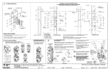
Illustrated Fitting Instructions
Step 2 (optional) Step 3
These instructions describe the steps to install a standard Yarra Ridge lock
for general application. For other Yarra Ridge variations and non-standard
applications, additional instructions may be required.
Read through all instruction steps before beginning installation. When
replacing an older lock, modify the existing installation holes in the door stile
and jamb if necessary.
To remove a Cylinder Plug and install a Keyed Cylinder in the Exterior
Assembly, remove the Base Plate Screw and lift off the Base Plate Assembly.
Remove and discard the Cylinder Plug.
Hold the Base Plate Assembly by the Spindle. Using the Alignment Markings
on the Base Plate as a guide, ensure the Cylinder Gear is orientated as
shown in Figure D.
Install the Keyed Cylinder into the Exterior Pull by matching the orientation
shown in Figures B and C.
Place the Base Plate Assembly onto the Exterior Pull. If the Base Plate does
not sit flush with the rear of the Exterior Pull, rotate the Spindle until it drops
into place. Replace the Base Plate Screw.
OR
OR
Keyed Cylinder
Exterior Pull
Spigot
Cylinder Plug
Base Plate
Screw
Spindle
Base Plate
Assembly
Figure B
Exterior Pull Assembly
Figure D
Cylinder Gear Orientation
Figure C
Installing a
Keyed Cylinder
Base Plate
Alignment
Markings
Cylinder Gear
Use the table below with Figure E to decide the correct length of the
Spindle. Add 8mm to thickness in table if using packers. If necessary,
use pliers or a vice to carefully break off the required number of
pre-notched portions of the Spindle to suit the door thickness.
Door thickness
27.5 to 21.3mm
33.8 to 27.6mm
40.1 to 33.9mm
46.4 to 40.2mm
Spindle preparation
Break off ‘3’ portions
Break off ‘2’ portions
Break off ‘1’ portion
Break off ‘0’ portions
Figure E
Spindle
Notch
Discard
Several pairs of Fixing Screws are provided to suit different door
thicknesses. Use the table below to identify which are the correct
length Fixing Screws. Add 8mm to thickness in table if using packers.
Figure F
Door thickness
27.5 to 21.3mm
33.8 to 27.6mm
40.1 to 33.9mm
Screw selection
1” Fixing Screw
1 ” Fixing Screw¼
1 ½” Fixing Screw
46.4 to 40.2mm
1 ¾” Fixing Screw
Interior
14.0 mm
41.0 mm
41.0 mm
For optimal installation, ensure the door is rolling smoothly and closing
parallel into the jamb by lubricating and adjusting the rollers. Close the
door and lightly mark the door stile at the edge of the overlapping jamb.
Prepare three 9.0mm holes in the door stile as dimensioned below in
Figure A. Ensure the holes are straight and free from burr.
Door Stile
Exterior
Door Jamb
Mark
Door Stile
9.0 mm
Mark and measure
from this edge
Figure A
(PK0233) YR4000 Instructions (Trade A4) R5.cdr
IMPORTANT: If installing an EGRESS Yarra Ridge D-Pull, test the lock
after installation to ensure correct operation.
The interior lever on the EGRESS D-Pull must allow unlocking at all times.
Test by locking the exterior by key, then rotate the interior lever.
The interior lever must be free to retract the beaks.
E
T
H
L
C
I
S
Y
P
C
A
E
C
R
K
E
A
S
G
A
I
N
E
G
L
P

/