Page is loading ...

24739476
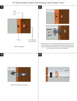
NOTE: If door does not have a cutout for
cabling inside lock stile, door must be
routed. Refer to 33/3550AWDC wood
door template #24731408.
!
1-Point
Latch
(LBL)
2-Point
Latch
includes these
additional
parts
Fire-Rated
Devices
include these
additional
components
Metal Edge
Wrap required
for 60 and
90-minute
applications
33/3550AWDC
Installation Instructions

2
1 OVERVIEW AND DOOR PREPARATION
TABLE OF CONTENTS
INSTALLATION
Overview and Door Preparation pg 2-3
Fire Barrier pg 4-5
Latch Installation pg 6
Cable Installation pg 7
Device Installation pg 8-9
ADJUSTMENT
Device Adjustment pg 10-11
Strikes and Fire Pin pg 12-13
Bottom Latchbolt Clearance pg 14
Top Strike and Covers pg 15
Troubleshooting pg 16
1.
2.
3.
4.
5.
6.
7.
8.
9.
10.
33/3550AWDC
Instead of traditional rods, concealed vertical cables are utilized, making use of a proven technology
that enables quick installation and allows for easy maintenance. Simplified sizing, ease of adjustment
and greater door integrity make the Wood Door Concealed exit device a more secure solution, without
the complexity associated with traditional concealed systems. Another key benefit of the system is the
ability to make adjustments to the system by simply removing the scalp plate from the edge of the
door.
If you have any questions or comments please visit the resources below or give us a call so we can
help get you on your way. Thank you for your continued support of Von Duprin.
Technical Support hot line: 877-671-7011
Scan this QR code or visit us online at kc.allegion.com to access the
Allegion Knowledge Center.
Need a reader for your phone?
For iPhone: QR Reader
For Android: QR Barcode Scanner

3
1 (continued)
1a For 60 and 90-minute applications, install metal edge
wrap.
1b With door laying fl at, draw horizontal device center
line (
C
L
).
RHR shown
(LHR opposite)
NOTE:
Centerline is
predetermined by cutout.
!
1c If necessary, prepare center case mounting holes.
3¹⁄₈"
3¹⁄₈"
Device
Sex bolts Ø ¹³⁄₃₂" thru (Pre-prepped at factory)
Trim Ø ¹⁄₂" thru (Enlarge existing holes)
(2 places)
RHR shown
(LHR opposite)
Device
1¹⁄₂" Backset
1d If necessary, prepare door for top strike cutout.
⁵⁄₈"
Cut out material
this side only
Latch
Push side of door, RHR shown
2"
1³⁄₁₆"

4
2 FIRE BARRIER
I Fire application only
I Fire components must be installed to maintain fi re rating
of opening.
2a Peel adhesive backing from intumescent and apply to
trim side of fi re barrier.
I Intumescent must be properly aligned before exposed
adhesive contacts fi re barrier. Adhesive is permanent and
not repositionable.
Trim Side
Trim Side
OR
RHR
LHR
a-1
a-2
a-1
a-2
2b Remove appropriate knockouts for device and trim.
Exit Only (EO) shown
RHR
Exit Only (EO) shown
LHR

5
2 (continued)
2c With fi re barrier in correct orientation, slide barrier into
door pocket.
Trim Side
RHR shown
2d Secure fi re barrier to inside of pocket with 4 screws.
Trim
Model
Exit Only
386
386
388
550
392-6
360
360
360
360
360
Trim
Function
EO
DT
NL
NL
DT
-
L
L-BE
L-DT
T
T-BE
Right Hand Reverse (RHR)
Remove the knockouts listed below
A B C D
A B C D H
A B C D G H
A B C D E J
A B C D
(If mounted below, remove E, J)
A B C D F G H
Left Hand Reverse (LHR)
Remove the knockouts listed below
F G H I
C F G H I
B C F G H I
E F G H I J
F G H I
(If mounted below, remove E, J)
A B C F G H I
FIRE BARRIER KNOCKOUT TABLE
RHR LHR

6
3 LATCH INSTALLATION
3a Confi rm top latch is marked for EXIT DEVICES ONLY,
then remove label.
ATTENTION:
FOR USE WITH
EXIT DEVICES ONLY
3b Connect cable end fi tting(s) to latch(es).
I For 2-point latches, the top cable is the longer of the two
cables. Top cable is silver, bottom cable is black.
Top Bottom
For 2-Point
Latch Only
Pull down on
cable link
Slide cable end
into cable link
b-2
b-1
Bend cable slightly
to access
cable link,
then
install
cable
link
cable
link
3c Slide latch(es) into door pocket.
I Clear cable channel of debris fi rst if necessary.
Push Side
of Door
Push Side
of Door
Bottom
For 2-Point
Latch Only
To p
Push
Side
Push
Side
3d Secure latch(es).
RHR shown
Push Side
of Door
Push Side
of Door
BottomTo p
For 2-Point Latch Only
#25 Drill, Pilot 1¹⁄₂" Deep x4
#10 x 1¹⁄₂"
#25 Drill, Pilot 1¹⁄₂" Deep x4
If using metal edge
wrap, mount latches
using this screw
3e Perform cable binding check at mortise pocket.
TOP
Pulling on top cable should
lock and unlock top latch.
(2-pt only) Pulling on
bottom cable should
retract bottom latch.
3f Prepare door for hanging.
Pull bottom cable taut enough so bottom bolt will not
drag against floor, and tape cable end to door edge
(f-2). This holds cable in place, preventing it from
dropping into door channel. Tape bottom bolt in place
(f-3).
Pull top cable taut and tape cable
end to door edge (f-1).
f-3
f-2
f-1
For 2-Point
Latch Only
3g Hang door on frame.
I For 2-point latches, bottom latch cannot be in locked
position while hanging door on frame. Latch must be
retracted.

7
4 CABLE INSTALLATION
4a Insert cable end fi tting(s) into center slide.
I Be sure to attach top cable to top end of center slide
(marked “Top”)
Remove tape from door edge, then repeat
process to install bottom cable into bottom spool.
For 2-Point Latch Only
a-6
Pull top cable thru mortise
opening (a-1).
Rotate spool using hex
wrench to reveal cable hole
in spool (a-2), if it is not
visible or only partially
visible.
Insert cable end into spool
(a-3).
Tu r n spool screw
counterclockwise (a-4) to
rotate spool until cable end is
beneath profile of center
slide (a-5).
a-1
a-2
a-3
⁵⁄₃₂"
hex
wrench
a-4
a-5
4b Take up top cable slack only.
I A fl ashlight would be useful during adjustment.
Position center slide as shown. Turn top
spool screw counterclockwise to
tighten (b-1) until center slide is no
longer hanging outside door.
NOTE:
If clicking noises are heard
during counterclockwise adjustment,
unwind the cable with one-half turn
clockwise. Then, continue counterclock-
wise adjustment. If clicking persists,
check to be sure cable is not caught on
an edge.
!
⁵⁄₃₂"
hex wrench
Center slide
is resting on
step of door
pocket
b-1
Do not adjust
bottom cable
at this time.
!
4c Secure center slide.
¹⁄₈" Drill, Pilot 1" Deep x2
#8 x 1"
4d Adjust top spool.
Put top latch in locked
position (d-1).
Confirm top latch is
still locked (d-4).
Tu r n top spool screw
(d-2) until bottom edge of
spool is just above line
(d-3).
Bottom
edge of
spool
Locked
d-1
d-2
d-3
d-4
If latch won’t
lock, top spool
screw was
overtightened in
Step 4b and
needs to be
backed out
clockwise.
!
NOTE: Top latch must be placed
in locked position prior to making
top adjustment.
!
Released Locked
NOTE: No further top spool adjustment needed.
Put hex wrench away until Step 8b.
!

8
5 DEVICE INSTALLATION
5a If necessary, cut device.
Door
1¹⁄₂" (38 mm)
Recommended
Jamb
Jamb
Cover Plate
Flush
Temporarily Remove
Anti-Rattle Clip
5b Install lift fi nger(s) and retainer clip(s).
Lightly tighten locking screw (b-7).
Install retainer clip against lift finger,
snapping it into the slot of the lift
finger screw.
For 2-Point Latch Only
Confirm lift finger screw is
free to rotate (b-8).
!
Slide L-shaped lift finger thru upper
block on front of center case.
Insert lift finger screw and turn
clockwise with screwdriver to raise
lift finger until the slot
aligns with diameter
of screw hole.
Repeat steps b-1 thru
b-8 for lower block of
center case.
It may be necessary to rotate
the lift finger screw to realign
retainer clip and lift finger holes.
!
(1³⁄₄" door)
(2¹⁄₄" door)
Bottom
To p
b-2
b-3
b-5
b-6
b-7
b-4
b-9
slot
b-8
Using tube of grease provided, apply grease to interior of rod connector
sleeve in locations shown (b-1). With device center case hanging over edge
of table, slide rod connector sleeve over top end of center case in
orientation shown (b-2), then insert mounting screw thru hole in center case
and slot in clip (b-3).
Block may need to
be pushed down
to insert screw
b-1

9
5 (continued)
5c Attach center case to door.
Sex Bolts
Thru-bolting Trim
(1³⁄₄" door)
(2¹⁄₄" door)
(1³⁄₄" door)
(2¹⁄₄" door)
OR
Block may need to be pushed up to
access screw.
!
Do not overtighten
center case to door
(door edge cover
plate won’t fit).
5d Mark and prepare 2 holes.
Surface Mount
¹⁄₈" Drill, Pilot 1" Deep
Sex Bolts
OR
¹³⁄₃₂" Drill thru
d-1 d-2
d-3
5e Install end cap bracket and end cap.
#10 x 1¹⁄₄" Wood screw
(Surface mount WDC)
#10-24 x ³⁄₄"
(Sex bolts, 1³⁄₄" door)
#10-24 x 1¹⁄₈"
(Sex bolts, 2¹⁄₄" door)
e-1 e-2

10
6 DEVICE ADJUSTMENT
ADJUSTMENT COMPONENTS
Push Side of Door
Center Case
Pull Side / Edge of Door
Center Slide
Reverse Angle
For 2-point
latch only
*
Top lift finger screw:
Adjusts release point of latches
Bottom lift finger screw*:
Adjusts release point of latches
Top locking screw:
Locks lift finger screw adjustment
Bottom locking screw*:
Locks lift finger screw adjustment
Top spool screw:
Sizes cable to door height
Bottom spool screw*:
Sizes cable to door height and
undercut
Bottom lift finger*:
Transfers motion from exit device
spool inputs
Top spool input:
Transfers motion from lift finger to
latch
Top lift finger:
Transfers motion from exit device
spool inputs
Bottom spool input*:
Transfers motion from lift finger to
latch

11
6 (continued)
6a Adjust device for top latch retraction position.
Tu r n top lift finger screw
counterclockwise an
additional 2 full turns.
Put top latch in
locked position.
While pressing down on top lift finger
screw (a-7) so it is seated, tighten top
locking screw (a-8).
a-1
a-2
a-7
a-8
a-4
a-3 a-5
a-6
With pushpad depressed, you should be
able to release top latch with your finger,
as shown below.
Using your finger, put top
latch in locked position.
a-9
a-10
If using 360L / 360T trim, turn and hold
lever / thumb turn instead.
!
2 additional
turns
Maintain downward pressure on screwdriver
and turn top lift finger screw counterclock-
wise to lower lift finger. With other hand,
press on top latchbolt. STOP as soon as top
latch releases.
Locked Released
Steps marked with a symbol are different if using 360L / 360T trim.
If top latch releases,
adjustment is good;
proceed to Step a-5.
Otherwise, continue to
Step a-3.
Depress and HOLD push pad (or dog device)
until Step a-6.
If using 360L / 360T trim,
release lever / thumb turn
instead.
Release push pad.
6b Adjust device for bottom latch retraction positon.
For 2-Point Latch Only
Push up on bottom lift finger screw
so it is seated, and tighten the bottom
locking screw.
Depress and HOLD
push pad (or dog
device) until Step b-4.
Maintain upward pressure on screwdriver and
turn bottom lift finger screw (b-2) counter-
clockwise to adjust past point where bottom lift
finger contacts bottom spool input (b-3).
Continue adjusting until bottom spool input
reaches end of travel or until bottom lift finger
reaches max adjust.
max adjust
0
b-1
b-2
b-4
b-5
b-6
b-3
If using 360L / 360T trim,
release lever / thumb turn
instead.
Release push pad.
If using
360L / 360T trim,
turn and hold
lever / thumb turn
instead.

12
7 STRIKES AND FIRE PIN
7a Prepare door frame for top strike.
Metal
Wood
#25 x ³⁄₄" Deep x2
#10-24
Center punch + ¹⁄₁₆" Pilot
¹⁄₈" Drill
Pilot 1" Deep x2
OR
With flat end of strike against stop, center strike to marks on frame (a-3).
Use a pencil to trace contour of the two slotted holes (a-4).
Mark the bottom center point of each slot (a-5) and prepare door frame as
shown.
From push side of door, with door nearly
closed, use straight edge to transfer
location of inside edges of top latch
housing to underside of stop (a-1).
Edge of stop
or gasket
From pull side of door,
transfer marks to
underside of
frame (a-2).
PUSH SIDE
OF DOOR
PULL SIDE
OF DOOR
a-1
a-2
a-5
a-3
a-4
Do not drill 3rd hole at this time.
!
If using a door seal or gasket, install first.
!
7b Install 2 top strike screws using the slot features on
the strike.
Typical installation
requires 1-thick and
1-thin shim. Adjust as
necessary.
150 Top Strike
(metal)
(wood)
7c Perform top latch functional test.
c-1. Close door.
c-2. With door closed, top latch should be secure.
c-3. If door fails to relatch, adjust top strike location.
c-4. Depress pushbar. Door should begin to open when
pushbar is nearly fully depressed. If necessary, refer to
Step 6A to readjust top latch retraction position.

13
7 (continued)
7d Prepare fl oor for bottom strike.
For 2-Point Latch Only
⁷⁄₈" ¹⁄₂"
1¹⁄₄"
1"
³⁄₈" Dia. x 1¹⁄₄" Deep
2 places
Chisel out pocket
¹⁄₂" Deep
Latch
Push Side
Pull Side
1" 1"
7e Install bottom strike.
For 2-Point Latch Only
Clear holes of debris, then
drop in anchors (slotted end
first)
Secure the anchors using a
hammer and punch
Install strike plate and secure
with 2 screws
450 Bottom Strike
IMPORTANT:
Anchors must
be below flush.
!
e-2
e-1
e-3
7f For Fire LBL applications only, install fi re pin.
I See instructions packaged with fi re pin.

14
8 BOTTOM LATCHBOLT CLEARANCE
8a Remove tape holding bottom bolt in place from bottom
of door.
For 2-Point Latch Only
8b Adjust bottom latchbolt clearance.
I A fl ashlight would be useful during adjustment.
Push bottom spool input upward until flat of input
hits stop. Input should lock in place.
For 2-Point Latch Only
Reach inside center slide and push downward on shelf of top
spool input to release top latch, if not already retracted. Line
shown in Step 4d-3 should no longer be visible.
stop
b-1
b-2
b-3
Tu r n bottom spool screw counterclockwise approximately
20 turns to remove slack. Continue turning until bolt just
clears top of strike (b-4).
bolt
strike
b-4
³⁄₈" standard
undercut
NOTE:
If clicking noises are heard during counterclockwise
adjustment, unwind the cable with one-half turn clockwise.
Then, continue counterclockwise adjustment. If clicking
persists, check to be sure cable is not caught on an edge.
!
8c Perform bottom latch functional test.
For 2-Point Latch Only
c-1. Confi rm bottom latchbolt does not drag against fl oor when
door is opened.
c-2. With door closed, bottom latch should be secure.

15
9 TOP STRIKE AND COVERS
9a Adjust top strike as necessary, then install the third
strike screw to fi x the strike position.
Metal
Wood
#25 x ³⁄₄" Deep
#10-24
¹⁄₈" Drill
Pilot 1" Deep
OR
(metal) (wood)
9b For fi re devices, prepare door edge and cover plate.
I Fire application only
I Intumescent must be properly aligned before exposed
adhesive contacts cover plate. Adhesive is permanent and
not repositionable.
³⁄₁₆" Drill, Pilot 1" Deep x2
Insert plastic
anchors
Peel adhesive backing from
intumescent and apply to
back side of cover plate
b-1
b-1
b-2
9c Install cover plate to door edge, then completely
tighten down center case screws.
For non-fire devices, first
prepare door edge
¹⁄₈" Drill, Pilot 1" Deep x2
c-2
c-1
9d Install center case cover.
Remove protective
film from pushbar

© Allegion 2015
Printed in U.S.A.
24739476 Rev. 4/15-b
Customer Service
1-877-671-7011 www.allegion.com/us
10 TROUBLESHOOTING
If latches do not retract when pushpad is depressed:
Remove cover plate from edge of door
Pull down on top spool input. If the top latch fails to actuate, readjust top spool (Steps 4d-1 thru 4d-4).
Pull up on bottom spool input. If the bottom latch fails to actuate, readjust bottom latch clearance (Steps 8b-1 thru 8b-4).
If both actuate and the door is not functioning, proceed to next check.
Remove center case cover
Check lift finger screws to ensure they are still fully seated. If unseated, loosen
locking screw, and while applying pressure to the head of the lift finger screw to
seat it, tighten locking screw. If door is not functioning, proceed to next step.
With both lift finger screws fully seated, loosen top and bottom locking
screws, turn lift finger screws clockwise to end of travel, and repeat
device adjustment, Step 6.
If bottom spool input does not move during Steps 6b-2 / b-3:
Loosen bottom spool screw 10 turns.
If the 33/3550AWDC center case cover is difficult to install:
Loosen bottom screw installed in Step 5c and lift rod connector sleeve until it will go no higher, then retighten screw.
Seated Unseated
/