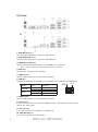
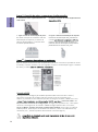
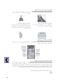
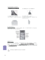
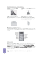
ECS B85H3-M9 boasts a robust Intel B85 chipset and LGA1150 socket, supporting up to 16GB of dual-channel DDR3 memory and various expansion options, including PCI Express x16 Gen3 and USB 3.0 ports, offering a versatile platform for diverse computing needs.
ECS B85H3-M9 boasts a robust Intel B85 chipset and LGA1150 socket, supporting up to 16GB of dual-channel DDR3 memory and various expansion options, including PCI Express x16 Gen3 and USB 3.0 ports, offering a versatile platform for diverse computing needs.


-
 1
1
-
 2
2
-
 3
3
-
 4
4
-
 5
5
-
 6
6
-
 7
7
-
 8
8
-
 9
9
-
 10
10
-
 11
11
-
 12
12
-
 13
13
-
 14
14
-
 15
15
-
 16
16
-
 17
17
-
 18
18
-
 19
19
-
 20
20
-
 21
21
-
 22
22
-
 23
23
-
 24
24
-
 25
25
-
 26
26
-
 27
27
-
 28
28
-
 29
29
-
 30
30


ECS B85H3-M9 boasts a robust Intel B85 chipset and LGA1150 socket, supporting up to 16GB of dual-channel DDR3 memory and various expansion options, including PCI Express x16 Gen3 and USB 3.0 ports, offering a versatile platform for diverse computing needs.
Ask a question and I''ll find the answer in the document
Finding information in a document is now easier with AI
in other languages
- español: ECS B85H3-M9 Manual de usuario
- Deutsch: ECS B85H3-M9 Benutzerhandbuch
- português: ECS B85H3-M9 Manual do usuário
Related papers
Other documents
-
Gigabyte GA-C847N User manual
-
Gigabyte GA-A55M-S2HP User manual
-
Gigabyte GA-EG41MF-S2H User manual
-
Gigabyte GA-EG41MF-US2H User manual
-
Gigabyte GA-EG43M-S2H User manual
-
Gigabyte GA-8IPE1000MK User manual
-
Gigabyte GA-F2A75-D3H User manual
-
Gigabyte GA-F2A85X-UP4 User manual
-
Gigabyte GA-990FXA-UD3 User manual
-
Gigabyte GA-8VT800 User manual