Page is loading ...

2
Table of Contents
INTRODUCTION .......................................................................................................................... 3
ASSEMBLY ................................................................................................................................... 6
Setting up the Tripod .................................................................................................................. 6
Attaching the Telescope Tube to the Mount............................................................................... 7
Moving the Telescope Manually ................................................................................................ 8
Installing the Diagonal & Eyepiece (Refractor) – 60AZ............................................................ 8
Installing the Diagonal & Eyepiece (Refractor) – 50AZ............................................................ 8
Installing the Eyepiece on the Newtonian .................................................................................. 9
Installing & Using the Barlow Lens ........................................................................................... 9
Installing & Using the 1.5x Erecting Eyepiece – 50AZ ............................................................. 9
Installing the Finderscope......................................................................................................... 10
Aligning the Finderscope.......................................................................................................... 10
TELESCOPE BASICS ................................................................................................................. 11
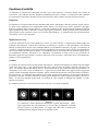
Image Orientation ..................................................................................................................... 12
Focusing.................................................................................................................................... 12
Calculating Magnification ........................................................................................................ 12
Determining Field of View....................................................................................................... 13
General Observing Hints........................................................................................................... 13
ASTRONOMY BASICS .............................................................................................................. 14
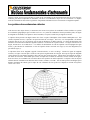
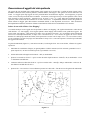
The Celestial Coordinate System.............................................................................................. 14
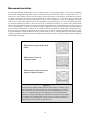
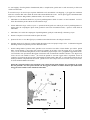
Motion of the Stars.................................................................................................................... 15
CELESTIAL OBSERVING ......................................................................................................... 16
Observing the Moon ................................................................................................................. 16
Observing the Planets ............................................................................................................... 16
Observing the Sun..................................................................................................................... 16
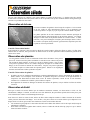
Observing Deep-Sky Objects.................................................................................................... 17
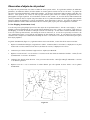
Seeing Conditions..................................................................................................................... 19
ASTROPHOTOGRAPHY............................................................................................................ 20
Short Exposure Prime Focus Photography ............................................................................... 20
Planetary & Lunar Photography with Special Imagers............................................................. 20
CCD Imaging for Deep-Sky Objects ........................................................................................ 20
Terrestrial Photography ............................................................................................................ 20
TELESCOPE MAINTENANCE.................................................................................................. 21
Care and Cleaning of the Optics ............................................................................................... 21
Collimation of a Newtonian...................................................................................................... 21
OPTIONAL ACCESSORIES ..................................................................................................... 24
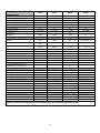
POWERSEEKER SPECFICATIONS.......................................................................................... 25

3
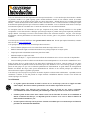
Congratulations on your purchase of a PowerSeeker telescope. The PowerSeeker Series of telescopes come in
several different models and this manual covers four models mounted on Alt-Az Mounts ((an altazimuth is the
simplest type of mount with two motions – altitude (up & down) and azimuth (side-to-side)) --- 50mm refractor,
60mm refractor, 70mm refractor, and a 76mm Newtonian. The PowerSeeker Series is made of the highest quality
materials to ensure stability and durability. All this adds up to a telescope that gives you a lifetime of pleasure with
a minimal amount of maintenance.
These telescopes were designed for the First Time Buyer offering exceptional value. The PowerSeeker series
features a compact and portable design with ample optical performance to excite any newcomer to the world of
amateur astronomy. In addition, your PowerSeeker telescope is ideal for terrestrial observations which will open
your eyes with its superb high power viewing.
PowerSeeker telescopes carry a two year limited warranty. For details see our website at www.celestron.com
Some of the many standard features of the PowerSeeker include:
• All coated glass optical elements for clear, crisp images.
• Smooth functioning, rigid altazimuth mount with easy pointing to located objects.
• Preassembled aluminum tripod ensures a stable platform.
• Quick and easy no-tool set up.
• CD-ROM “The SkyX -- astronomy software which provides education about the sky and printable sky maps.
• All models can be used terrestrially as well as astronomically with the standard accessories included.
Take time to read through this manual before embarking on your journey through the Universe. It may take a few
observing sessions to become familiar with your telescope, so you should keep this manual handy until you have
fully mastered your telescope’s operation. The manual gives detailed information regarding each step as well as
needed reference material and helpful hints to make your observing experience simple and pleasurable as possible.
Your telescope is designed to give you years of fun and rewarding observations. However, there are a few things to
consider before using your telescope that will ensure your safety and protect your equipment.
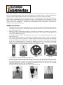
Warning
y Never look directly at the sun with the naked eye or with a telescope (unless you have the proper
solar filter). Permanent and irreversible eye damage may result.
y Never use your telescope to project an image of the sun onto any surface. Internal heat build-up can
damage the telescope and any accessories attached to it.
y Never use an eyepiece solar filter or a Herschel wedge. Internal heat build-up inside the telescope can
cause these devices to crack or break, allowing unfiltered sunlight to pass through to the eye.
y Do not leave the telescope unsupervised, either when children are present or adults who may not be
familiar with the correct operating procedures of your telescope.

4
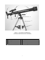
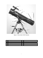
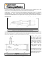
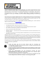
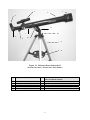
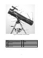
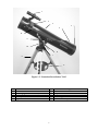
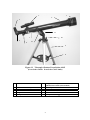
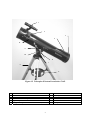
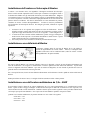
Figure 1-1 PowerSeeker 60AZ Refractor
(PowerSeeker 50AZ & PowerSeeker 70AZ Similar)
1. Objective Lens 7. Altitude Slow Motion Rod Assembly (not on 50AZ)
2. Telescope Optical Tube 8. Accessory Tray
3. Finderscope 9. Tripod
4. Eyepiece 10. Azimuth Lock (not on 50AZ)
5. Diagonal 11. Alt-Az Mount
6. Focus Knob 12. Altitude Locking Knob
1
2
3
4
12
7
6
5
11
10
9
8

5
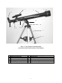
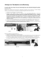
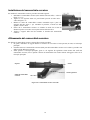
Figure 1-2 PowerSeeker 76AZ Newtonian
1. Finderscope 7. Azimuth Lock
2. Eyepiece 8. Accessory Tray
3. Collimation Adjustment Screws (in rear) 9. Tripod
4. Telescope Optical Tube 10. Alt-Az Mount
5. Primary Mirror 11. Altitude Lock
6. Altitude Slow Motion Rod Assembly 12. Focus Knob
1
2
4
5
3
12
6
10
9
11
7
8

6
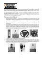
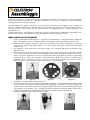
This section covers the assembly instructions for your PowerSeeker telescope. Your telescope should be set up
indoor the first time so that it is easy to identify the various parts and familiarize yourself with the correct assembly
procedure before attempting it outdoor.
Each PowerSeeker comes in one box. The pieces in the box for all models are – optical tube, altazimuth mount, and
“The SkyX” CD-ROM. The 50AZ includes 0.96” accessories – 20mm eyepiece, 12mm eyepiece, 4mm eyepiece, 3x
Barlow lens, and 1.5x erecting eyepiece.
The 60AZ, 70AZ & 76AZ includes 1.25” accessories – 20mm eyepiece (erect image for 76AZ), 4mm eyepiece,
3x Barlow lens, erect image diagonal for 60AZ.
S
S
e
e
t
t
t
t
i
i
n
n
g
g
u
u
p
p
t
t
h
h
e
e
T
T
r
r
i
i
p
p
o
o
d
d
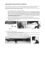
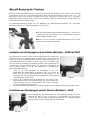
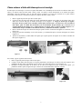
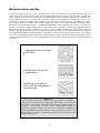
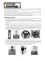
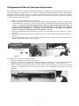
1. Remove the tripod from the box (Figure 2-1). The tripod comes preassembled so that the set up is very
easy. Each tripod is different for each model but looks somewhat similar to the photos shown below.
2. Stand the tripod upright and pull the tripod legs apart until each leg is fully extended and then push down
slightly on the tripod leg brace (Figure 2-2). The very top of the tripod is called the tripod head
(AZ mount).
3. Next, we will install the tripod accessory tray (Figure 2-3) onto the tripod leg brace (center of Figure 2-2).
4. On the bottom of the tripod tray is a screw attached to the center (except the 50AZ). The screw attaches
into a threaded hole in the center of the tripod leg brace by turning it clockwise - note: pull up slightly on
the tripod leg brace to make it easy to attach. Continue turning the tray until hand tight – don’t over tighten
the tray. The 50AZ is slightly different as you unthread a small knob in the center of the tray (see Figure
2-3a) and then put the tray over the threaded hole and tighten the knob to secure the tray.
Figure 2-1 Figure 2-2 Figure 2-3 Figure 2-3a
5. The tripod is now completely assembled (Figure 2-4).
6. You can extend the tripod legs to the height you desire. At the lowest level the height is about 27” (69cm)
and extends to about 47” (119cm). You unlock the tripod leg lock knobs at the bottom of each leg
(Figure 2-5) by turning them counterclockwise and pull the legs out to the height you want & then lock the
knobs securely. A fully extended tripod looks similar to the image in Figure 2-6.
7. The tripod will be the most rigid and stable at the lower heights.
Figure 2-4 Figure 2-5 Figure 2- 6

7
A
A
t
t
t
t
a
a
c
c
h
h
i
i
n
n
g
g
t
t
h
h
e
e
T
T
e
e
l
l
e
e
s
s
c
c
o
o
p
p
e
e
T
T
u
u
b
b
e
e
t
t
o
o
t
t
h
h
e
e
M
M
o
o
u
u
n
n
t
t
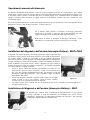
The telescope optical tube attaches to the altazimuth mount with the altitude slow motion rod assembly and the
respective knobs for the 60AZ, 70AZ and 76AZ. The 50AZ attaches directly to the altazimuth mount head.
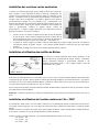
Before starting, remove the objective lens cap (refractor) or the front opening cap (Newtonian). To mount the
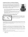
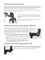
telescope tube to the mount for the 60AZ, 70AZ, and 76AZ:
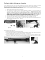
1 Remove the protective paper covering the optical tube.
2 Put the telescope optical tube inside the yoke (altazimuth) mount so that the altitude slow motion rod
assembly is on the same side as the altitude locking screw (see Figure 1-1). Note that on some telescopes
that the rod may be attached to the telescope optical tube. If the rod is not attached to the optical
tube, remove the screw from the mechanism (with the provided tool) shown on the far left of Figure
2-7 and put the rod in place as shown in Figure 2-7. Then, put the screw through the hole in the rod
and into the mechanism and tighten it.
3 Thread the altitude locking knob out so the hole is clear in the eyebolt (see Figure 2-8).
4 Put the rod of the assembly through the eyebolt and then tighten the altitude locking knob – Figure 2-9.
5 Thread the two knobs (one on either side of the mount) through the top of the mount into the threaded holes
in the optical tube and tighten – Figure 2-7.
Figure 2-7 Figure 2-8 Figure 2-9
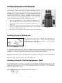
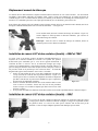
For the 50AZ, take the following steps:
1. Remove the protective paper covering the optical tube.
2. Place the telescope optical tube on the altazimuth mount so that the hole in the top of the optical tube
platform lines up with the holes in the mount head – see Figure 2-11.
3. Insert the altitude locking knob (see center of Figure 2-10) through the mount head and optical tube platform
(make sure the hole is clear all the way through before tightening the knob.
Figure 2-10 Figure 2-11

8
M
M
o
o
v
v
i
i
n
n
g
g
t
t
h
h
e
e
T
T
e
e
l
l
e
e
s
s
c
c
o
o
p
p
e
e
M
M
a
a
n
n
u
u
a
a
l
l
l
l
y
y
The PowerSeeker Alt-Az mount is easy to move wherever you want to point it. For the 60AZ, 70AZ, and 76AZ the
up and down (altitude) is controlled by the altitude locking knob (Figure 2-12). The side-to-side (azimuth) is
controlled by the azimuth lock (Figure 2-12). When both knobs are loose you can find your objects easily (through
the finderscope) and then lock the controls.
For fine adjustments in altitude, you turn the knurled ring of the altitude slow motion rod (when the altitude lock is
tight) in either direction – see Figure 2-9.
For the 50AZ model, loosen the altitude locking knob – Figure 2-9 and
then move the telescope in the desired location you want and once
there tighten the altitude locking knob.
Note: Before tightening the altitude locking knob, the location you are
seeking should be located in the finderscope.
Figure 2-12
I
I
n
n
s
s
t
t
a
a
l
l
l
l
i
i
n
n
g
g
t
t
h
h
e
e
D
D
i
i
a
a
g
g
o
o
n
n
a
a
l
l
&
&
E
E
y
y
e
e
p
p
i
i
e
e
c
c
e
e
(
(
R
R
e
e
f
f
r
r
a
a
c
c
t
t
o
o
r
r
)
)
–
–
6
6
0
0
A
A
Z
Z
&
&
7
7
0
0
A
A
Z
Z
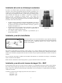
The diagonal is a prism that diverts the light at a right angle to the light path of
the refractor. This allows you to observe in a position that is more comfortable
than if you had to look straight through. This diagonal is an erect image model
that corrects the image to be right side up and oriented correctly left-to-right
which is much easier to use for terrestrial observing. Also, the diagonal can be
rotated to any position which is most favorable for you. To install the diagonal
and eyepiece:
1. Insert the small barrel of the diagonal into the 1.25” eyepiece adapter of
the focus tube on the refractor – Figure 2-13. Make sure the two
thumbscrews on the eyepiece adapter do not protrude into the focuser
tube before installation and the plug up cap is removed from the
eyepiece adapter.
2. Put the chrome barrel end of one of the eyepieces into the diagonal and
tighten the thumb screw. Again, when doing this make sure the
thumbscrew is not protruding into the diagonal before inserting the
eyepiece.
3. The eyepieces can be changed to other focal lengths by reversing the procedure in step 2 above.
I
I
n
n
s
s
t
t
a
a
l
l
l
l
i
i
n
n
g
g
t
t
h
h
e
e
D
D
i
i
a
a
g
g
o
o
n
n
a
a
l
l
&
&
E
E
y
y
e
e
p
p
i
i
e
e
c
c
e
e
(
(
R
R
e
e
f
f
r
r
a
a
c
c
t
t
o
o
r
r
)
)
–
–
5
5
0
0
A
A
Z
Z
The diagonal for the 50AZ is called a star diagonal where the prism corrects the
image to be right side up (erect image) but the image is reversed left-to-right. The
diagonal and eyepieces are .96” diameter sizes. All steps above are the same with
the 50AZ.
Figure 2-14
Figure 2-13

9
I
I
n
n
s
s
t
t
a
a
l
l
l
l
i
i
n
n
g
g
t
t
h
h
e
e
E
E
y
y
e
e
p
p
i
i
e
e
c
c
e
e
o
o
n
n
t
t
h
h
e
e
N
N
e
e
w
w
t
t
o
o
n
n
i
i
a
a
n
n
The eyepiece (or ocular) is an optical element that magnifies the image focused
by the telescope. Without the eyepiece it would be impossible to use the
telescope visually. Eyepieces are commonly referred to by focal length and
barrel diameter. The longer focal length (i.e., the larger the number) the lower
the eyepiece magnification (i.e., power). Generally, you will use low-to-
moderate power when viewing. For more information on how to determine
power, see the section on “Calculating Magnification”. The eyepiece fits
directly into the focuser of the Newtonian. To attach the eyepieces:
1. Make sure the thumbscrews are not protruding into the focuser tube.
Then, insert the chrome barrel of the eyepiece into the focus tube (remove
the plug up cap of the focuser first) and tighten the thumbscrews – see
Figure 2-15.
2. The 20mm eyepiece is called an erecting eyepiece since it corrects the
image so it is right side up and corrected left to right. This makes the
telescope useful for terrestrial viewing.
3. The eyepieces can be changed by reversing the procedure as described above.
I
I
n
n
s
s
t
t
a
a
l
l
l
l
i
i
n
n
g
g
&
&
U
U
s
s
i
i
n
n
g
g
t
t
h
h
e
e
B
B
a
a
r
r
l
l
o
o
w
w
L
L
e
e
n
n
s
s
Your telescope also comes with a 3x Barlow Lens which triples the
magnifying power of each eyepiece. However, the greatly magnified
images should only be used under ideal conditions – see the Calculating
Magnification section of this manual.
Figure 2-16
To use the Barlow lens with refractors, remove the diagonal and insert the Barlow directly into the focuser tube.
You then insert an eyepiece into the Barlow lens for viewing. You can also, insert the diagonal into the Barlow lens
and then use an eyepiece in the diagonal but you may not be able to reach focus with all eyepieces.
For Newtonian telescopes, insert the Barlowlens directly into the focuser. Then, insert an eyepiece into the Barlow
lens.
Note: Start by using a low power eyepiece as it will be easier to focus.
I
I
n
n
s
s
t
t
a
a
l
l
l
l
i
i
n
n
g
g
&
&
U
U
s
s
i
i
n
n
g
g
t
t
h
h
e
e
1
1
.
.
5
5
x
x
E
E
r
r
e
e
c
c
t
t
i
i
n
n
g
g
E
E
y
y
e
e
p
p
i
i
e
e
c
c
e
e
–
–
5
5
0
0
A
A
Z
Z
The PowerSeeker 50AZ comes with a 1.5x erecting eyepieces, primarily for daytime terrestrial viewing. This
eyepiece corrects the image you see in your telescope, so that it’s both right side up and corrected from left to right.
Install and use this eyepiece the same way you do with the Barlow Lens in the section above. You cannot use the
Barlow lens when using this eyepiece.
When using the erecting eyepiece, the power with various eyepieces is:
w/ 20mm = 45x
w/12mm = 75x
w/ 4mm = 225x
Figure 2-15

10
I
I
n
n
s
s
t
t
a
a
l
l
l
l
i
i
n
n
g
g
t
t
h
h
e
e
F
F
i
i
n
n
d
d
e
e
r
r
s
s
c
c
o
o
p
p
e
e
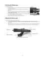
To install the finderscope:
1. Locate the finderscope (it will be mounted inside the finderscope bracket)
– see Figures 1-1 and 1-2.
2. Remove the knurled nuts on the threaded posts on the optical tube – see
Figure 2-17.
3. Mount the finderscope bracket by placing it over the posts protruding
from the optical tube and then holding it in place thread on the knurled
nuts and tightening them down.
4. Note that the finderscope should be oriented so that the larger diameter
lens is facing toward the front of the optical tube.
5. Remove the lens caps from both ends of the finderscope.
A
A
l
l
i
i
g
g
n
n
i
i
n
n
g
g
t
t
h
h
e
e
F
F
i
i
n
n
d
d
e
e
r
r
s
s
c
c
o
o
p
p
e
e
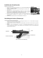
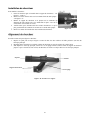
Use the following steps to align the finderscope:
1. Locate a distant daytime object and center it in a low power (20mm) eyepiece in the main telescope.
2. Look through the finderscope (the eyepiece end of the finderscope) and take notice of the position of the
same object.
3. Without moving the main telescope, turn the adjustment thumb screws located around the finderscope
bracket until the crosshairs of the finderscope are centered on the object chosen with the main telescope.
Figure 2-18 Finderscope with Bracket
Ob
j
ective Lens
Finderscope Bracket
Eyepiece
Adjustment Screws
Figure 2-17

11
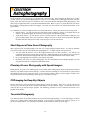
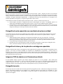
A telescope is an instrument that collects and focuses light. The nature of the optical design determines how the light is focused. Some
telescopes, known as refractors, use lenses, .and other telescopes, known as reflectors (Newtonians), use mirrors.
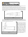
Developed in the early 1600s, the refractor is the oldest telescope design. It derives its name from the method it uses to focus
incoming light rays. The refractor uses a lens to bend or refract incoming light rays, hence the name (see Figure 3-1). Early designs
used single element lenses. However, the single lens acts like a prism and breaks light down into the colors of the rainbow, a
phenomenon known as chromatic aberration. To get around this problem, a two-element lens, known as an achromat, was introduced.
Each element has a different index of refraction allowing two different wavelengths of light to be focused at the same point. Most
two-element lenses, usually made of crown and flint glasses, are corrected for red and green light. Blue light may still be focused at a
slightly different point.
A Newtonian reflector uses a single concave mirror as its primary. Light enters the tube traveling to the mirror at the back end.
There light is bent forward in the tube to a single point, its focal point. Since putting your head in front of the telescope to look at the
image with an eyepiece would keep the reflector from working, a flat mirror called a diagonal intercepts the light and points it out the
side of the tube at right angles to the tube. The eyepiece is placed there for easy viewing.
Newtonian Reflector telescopes
replace heavy lenses with mirrors to
collect and focus the light, providing
much more light-gathering power for
the money spent. Because the light
path is intercepted and reflected out to
the side, you can have focal lengths up
to 1000mm and still enjoy a telescope
that is relatively compact and
portable. A Newtonian Reflector
telescope offers such impressive light-
gathering characteristics you can take
a serious interest in deep space
astronomy even on a modest budget.
Newtonian Reflector telescopes do
require more care and maintenance
because the primary mirror is exposed
to air and dust. However, this small
drawback does not hamper this type of
telescope’s popularity with those who
want an economical telescope that can
still resolve faint, distant objects.
Figure 3-1
A cutaway view of the light path of the Refractor optical design
Figure 3-2
Cutaway view of the light path of the Newtonian optical design

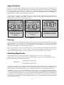
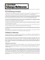
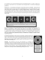
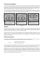
12
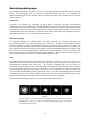
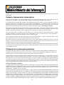
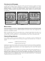
Image orientation as seen with
the unaided eye & using erecting
devices on refractors &
Newtonians
Inverted image, normal with
Newtonians & as viewed with
eyepiece directly in a refractor
Reversed from left to right, as
viewed using a Star Diagonal on
a refractor
I
I
m
m
a
a
g
g
e
e
O
O
r
r
i
i
e
e
n
n
t
t
a
a
t
t
i
i
o
o
n
n
The image orientation changes depending on how the eyepiece is inserted into the telescope. When using a star
diagonal with refractors, the image is right-side-up, but reversed from left-to-right (i.e., mirror image). If inserting
the eyepiece directly into the focuser of a refractor (i.e., without the diagonal), the image is upside-down and
reversed from left-to-right (i.e., inverted). However, when using the PowerSeeker refractor and the standard erect
image diagonal, the image is correctly oriented in every aspect.
Newtonian reflectors produce a right-side-up image but the image will appear rotated based on the location of the
eyepiece holder in relation to the ground. However, by using the erect image eyepiece supplied with the
PowerSeeker Newtonian, the image is correctly oriented.
Figure 3-3
F
F
o
o
c
c
u
u
s
s
i
i
n
n
g
g
To focus your refractor or Newtonian telescope, simply turn the focus knob located directly below the eyepiece
holder (see Figures 2-13, 2-14 and 2-15). Turning the knob clockwise allows you to focus on an object that is
farther than the one you are currently observing. Turning the knob counterclockwise from you allows you to focus
on an object closer than the one you are currently observing.
Note: If you wear corrective lenses (specifically glasses), you may want to remove them when observing with an
eyepiece attached to the telescope. However, when using a camera you should always wear corrective lenses to
ensure the sharpest possible focus. If you have astigmatism, corrective lenses must be worn at all times.
C
C
a
a
l
l
c
c
u
u
l
l
a
a
t
t
i
i
n
n
g
g
M
M
a
a
g
g
n
n
i
i
f
f
i
i
c
c
a
a
t
t
i
i
o
o
n
n
You can change the power of your telescope just by changing the eyepiece (ocular). To determine the
magnification of your telescope, simply divide the focal length of the telescope by the focal length of the eyepiece
used. In equation format, the formula looks like this:
Focal Length of Telescope (mm)
Magnification =
Focal Length of Eyepiece (mm)
Let’s say, for example, you are using the 20mm eyepiece that came with your telescope. To determine the
magnification you divide the focal length of your telescope (the PowerSeeker 60AZ for this example has a focal
length of 700mm) by the focal length of the eyepiece, 20mm. Dividing 700 by 20 yields a magnification of 35x.
Although the power is variable, each instrument under average skies has a limit to the highest useful magnification.
The general rule is that 60 power can be used for every inch of aperture. For example, the PowerSeeker 60AZ is
2.4” inches in diameter. Multiplying 2.4 by 60 gives a maximum useful magnification of 144 power. Although this
is the maximum useful magnification, most observing is done in the range of 20 to 35 power for every inch of
aperture which is 48 to 84 times for the PowerSeeker 60AZ telescope. You can determine the magnification for
your telescope the same way.

13
Note on Using High Powers – Higher powers are used mainly for lunar and sometimes planetary observing where
you can greatly enlarge the image, but remember that the contrast and brightness will be very low due to the high
magnification. Using the 4mm eyepiece together with the 3x Barlow lens gives extremely high power and can be
used on rare occasions – you will achieve the power but the image will be dark with low contrast because you have
magnified it to the maximum possible. For the brightest images with the highest contrast levels, use lower powers.
D
D
e
e
t
t
e
e
r
r
m
m
i
i
n
n
i
i
n
n
g
g
F
F
i
i
e
e
l
l
d
d
o
o
f
f
V
V
i
i
e
e
w
w
Determining the field of view is important if you want to get an idea of the angular size of the object you are
observing. To calculate the actual field of view, divide the apparent field of the eyepiece (supplied by the eyepiece
manufacturer) by the magnification. In equation format, the formula looks like this:
Apparent Field of Eyepiece
True Angular Field =
Magnification
As you can see, before determining the field of view, you must calculate the magnification. Using the example in
the previous section, we can determine the field of view using the same 20mm eyepiece that is supplied standard
with the PowerSeeker 60AZ telescope. The 20mm eyepiece has an apparent field of view of 50°. Divide the 50° by
the magnification, which is 35 power. This yields an actual (true) field of 1.4°.
To convert degrees to feet at 1,000 yards, which is more useful for terrestrial observing, simply multiply by 52.5.
Continuing with our example, multiply the angular field of 1.4° by 52.5. This produces a linear field width of 74
feet at a distance of one thousand yards.
G
G
e
e
n
n
e
e
r
r
a
a
l
l
O
O
b
b
s
s
e
e
r
r
v
v
i
i
n
n
g
g
H
H
i
i
n
n
t
t
s
s
When using any optical instrument, there are a few things to remember to ensure you get the best possible image.
y Never look through window glass. Glass found in household windows is optically imperfect, and as a
result, may vary in thickness from one part of a window to the next. This inconsistency can and will affect
the ability to focus your telescope. In most cases you will not be able to achieve a truly sharp image, while
in some cases, you may actually see a double image.
y Never look across or over objects that are producing heat waves. This includes asphalt parking lots on hot
summer days or building rooftops.
y Hazy skies, fog, and mist can also make it difficult to focus when viewing terrestrially. The amount of
detail seen under these conditions is greatly reduced.
y If you wear corrective lenses (specifically glasses), you may want to remove them when observing with an
eyepiece attached to the telescope. When using a camera, however, you should always wear corrective
lenses to ensure the sharpest possible focus. If you have astigmatism, corrective lenses must be worn at all
times.

14
Up to this point, this manual covered the assembly and basic operation of your telescope. However, to understand
your telescope more thoroughly, you need to know a little about the night sky. This section deals with observational
astronomy in general and includes information on the night sky and polar alignment.
T
T
h
h
e
e
C
C
e
e
l
l
e
e
s
s
t
t
i
i
a
a
l
l
C
C
o
o
o
o
r
r
d
d
i
i
n
n
a
a
t
t
e
e
S
S
y
y
s
s
t
t
e
e
m
m
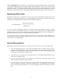
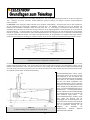
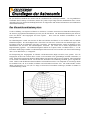
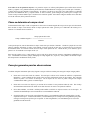
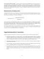
To help find objects in the sky, astronomers use a celestial coordinate system that is similar to our geographical co-
ordinate system here on Earth. The celestial coordinate system has poles, lines of longitude and latitude, and an
equator. For the most part, these remain fixed against the background stars.
The celestial equator runs 360 degrees around the Earth and separates the northern celestial hemisphere from the
southern. Like the Earth's equator, it bears a reading of zero degrees. On Earth this would be latitude. However, in
the sky this is referred to as declination, or DEC for short. Lines of declination are named for their angular distance
above and below the celestial equator. The lines are broken down into degrees, minutes of arc, and seconds of arc.
Declination readings south of the equator carry a minus sign (-) in front of the coordinate and those north of the
celestial equator are either blank (i.e., no designation) or preceded by a plus sign (+).
The celestial equivalent of longitude is called Right Ascension, or R.A. for short. Like the Earth's lines of longitude,
they run from pole to pole and are evenly spaced 15 degrees apart. Although the longitude lines are separated by an
angular distance, they are also a measure of time. Each line of longitude is one hour apart from the next. Since the
Earth rotates once every 24 hours, there are 24 lines total. As a result, the R.A. coordinates are marked off in units
of time. It begins with an arbitrary point in the constellation of Pisces designated as 0 hours, 0 minutes, 0 seconds.
All other points are designated by how far (i.e., how long) they lag behind this coordinate after it passes overhead
moving toward the west.
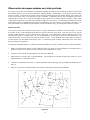
Figure 4-1
The celestial sphere seen from the outside showing R.A. and DEC.

15
M
M
o
o
t
t
i
i
o
o
n
n
o
o
f
f
t
t
h
h
e
e
S
S
t
t
a
a
r
r
s
s
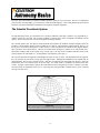
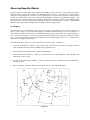
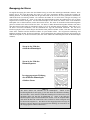
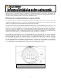
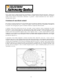
The daily motion of the Sun across the sky is familiar to even the most casual observer. This daily trek is not the
Sun moving as early astronomers thought, but the result of the Earth's rotation. The Earth's rotation also causes the
stars to do the same, scribing out a large circle as the Earth completes one rotation. The size of the circular path a
star follows depends on where it is in the sky. Stars near the celestial equator form the largest circles rising in the
east and setting in the west. Moving toward the north celestial pole, the point around which the stars in the northern
hemisphere appear to rotate, these circles become smaller. Stars in the mid-celestial latitudes rise in the northeast
and set in the northwest. Stars at high celestial latitudes are always above the horizon, and are said to be
circumpolar because they never rise and never set. You will never see the stars complete one circle because the
sunlight during the day washes out the starlight. However, part of this circular motion of stars in this region of the
sky can be seen by setting up a camera on a tripod and opening the shutter for a couple hours. The timed exposure
will reveal semicircles that revolve around the pole. (This description of stellar motions also applies to the southern
hemisphere except all stars south of the celestial equator move around the south celestial pole.)
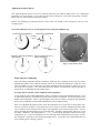
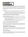
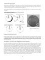
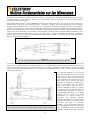
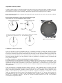
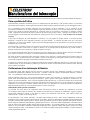
Figure 4-2
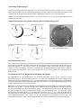
All stars appear to rotate around the celestial poles. However, the appearance of this
motion varies depending on where you are looking in the sky. Near the north celestial pole
the stars scribe out recognizable circles centered on the pole (1). Stars near the celestial
equator also follow circular paths around the pole. But, the complete path is interrupted by
the horizon. These appear to rise in the east and set in the west (2). Looking toward the
opposite pole, stars curve or arc in the opposite direction scribing a circle around the
opposite pole (3).

16
With your telescope set up, you are ready to use it for observing. This section covers visual observing hints for both
solar system and deep sky objects as well as general observing conditions which will affect your ability to observe.
O
O
b
b
s
s
e
e
r
r
v
v
i
i
n
n
g
g
t
t
h
h
e
e
M
M
o
o
o
o
n
n
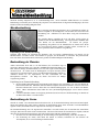
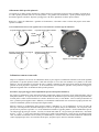
Often, it is tempting to look at the Moon when it is full. At this time, the
face we see is fully illuminated and its light can be overpowering. In
addition, little or no contrast can be seen during this phase.
One of the best times to observe the Moon is during its partial phases
(around the time of first or third quarter). Long shadows reveal a great
amount of detail on the lunar surface. At low power you will be able to
see most of the lunar disk at one time. Change to optional eyepieces for
higher power (magnification) to focus in on a smaller area.
Lunar Observing Hints
To increase contrast and bring out detail on the lunar surface, use optional filters. A yellow filter works well at
improving contrast while a neutral density or polarizing filter will reduce overall surface brightness and glare.
O
O
b
b
s
s
e
e
r
r
v
v
i
i
n
n
g
g
t
t
h
h
e
e
P
P
l
l
a
a
n
n
e
e
t
t
s
s
Other fascinating targets include the five naked eye planets. You can see
Venus go through its lunar-like phases. Mars can reveal a host of surface
detail and one, if not both, of its polar caps. You will be able to see the cloud
belts of Jupiter and the great Red Spot (if it is visible at the time you are
observing). In addition, you will also be able to see the moons of Jupiter as
they orbit the giant planet. Saturn, with its beautiful rings, is easily visible at
moderate power
.
Planetary Observing Hints
y Remember that atmospheric conditions are usually the limiting factor on how much planetary detail will be
visible. So, avoid observing the planets when they are low on the horizon or when they are directly over a
source of radiating heat, such as a rooftop or chimney. See the "Seeing Conditions" section later in this
section.
y To increase contrast and bring out detail on the planetary surface, try using Celestron eyepiece filters.
O
O
b
b
s
s
e
e
r
r
v
v
i
i
n
n
g
g
t
t
h
h
e
e
S
S
u
u
n
n
Although overlooked by many amateur astronomers, solar observation is both rewarding and fun. However,
because the Sun is so bright, special precautions must be taken when observing our star so as not to damage your
eyes or your telescope.
For safe solar viewing, use a proper solar filter that reduces the intensity of the Sun's light, making it safe to view.
With a filter you can see sunspots as they move across the solar disk and faculae, which are bright patches seen near
the Sun's edge.
y The best time to observe the Sun is in the early morning or late afternoon when the air is cooler.
y To center the Sun without looking into the eyepiece, watch the shadow of the telescope tube until it forms a
circular shadow.

17
O
O
b
b
s
s
e
e
r
r
v
v
i
i
n
n
g
g
D
D
e
e
e
e
p
p
-
-
S
S
k
k
y
y
O
O
b
b
j
j
e
e
c
c
t
t
s
s
Deep-sky objects are simply those objects outside the boundaries of our solar system. They include star clusters,
planetary nebulae, diffuse nebulae, double stars and other galaxies outside our own Milky Way. Most deep-sky
objects have a large angular size. Therefore, low-to-moderate power is all you need to see them. Visually, they are
too faint to reveal any of the color seen in long exposure photographs. Instead, they appear black and white. And,
because of their low surface brightness, they should be observed from a dark-sky location. Light pollution around
large urban areas washes out most nebulae making them difficult, if not impossible, to observe. Light Pollution
Reduction filters help reduce the background sky brightness, thus increasing contrast.
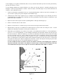
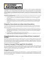
Star Hopping
One convenient way to find deep-sky objects is by star hopping. Star hopping is done by using bright stars to
"guide" you to an object. For successful star hopping, it is helpful to know the field of view of you telescope. If
you’re using the standard 20 mm eyepiece with the PowerSeeker telescope, your field of view is approximately 1.4º
or so. If you know an object is 3º away from your present location, then you just need to move about two fields of
view. If you’re using another eyepiece, then consult the section on determining field of view. Listed below are
directions for locating two popular objects.
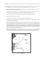
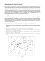
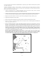
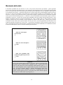
The Andromeda Galaxy (Figure 5-1), also known as M31, is an easy target. To find M31:
1. Locate the constellation of Pegasus, a large square visible in the fall (in the eastern sky, moving toward the
point overhead) and winter months (overhead, moving toward the west).
2. Start at the star in the northeast corner—Alpha (D) Andromedae.
3. Move northeast approximately 7°. There you will find two stars of equal brightness—Delta (G) and Pi (S)
Andromeda—about 3° apart.
4. Continue in the same direction another 8°. There you will find two stars—Beta (E) and Mu (P) Andromedae—
also about 3° apart.
5. Move 3° northwest—the same distance between the two stars—to the Andromeda galaxy.
Figure 5-1

18
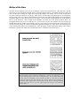
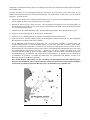
Star hopping to the Andromeda Galaxy (M31) is a snap, since all the stars needed to do so are visible to the naked
eye.
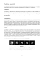
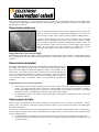
Star hopping will take some getting used to and objects that don’t have stars near them that are visible to the naked
eye are challenging. One such object is M57 (Figure 5-2), the famed Ring Nebula. Here's how to find it:
1. Find the constellation of Lyra, a small parallelogram visible in the summer and fall months. Lyra is easy to pick
out because it contains the bright star Vega.
2. Start at the star Vega—Alpha (D) Lyrae—and move a few degrees southeast to find the parallelogram. The four
stars that make up this geometric shape are all similar in brightness, making them easy to see.
3. Locate the two southernmost stars that make up the parallelogram—Beta (E) and Gamma (J) Lyra.
4. Point about halfway between these two stars.
5. Move about ½° toward Beta (E) Lyra, while remaining on a line connecting the two stars.
6. Look through the telescope and the Ring Nebula should be in your field of view. The Ring Nebula’s angular
size is quite small and difficult to see.
7. Because the Ring Nebula is rather faint, you may need to use “averted vision” to see it. “Averted vision” is a
technique of looking slightly away from the object you’re observing. So, if you are observing the Ring Nebula,
center it in your field of view and then look off toward the side. This causes light from the object viewed to fall
on the black and white sensitive rods of your eyes, rather than your eyes color sensitive cones. (Remember that
when observing faint objects, it’s important to try to observe from a dark location, away from street and city
lights. The average eye takes about 20 minutes to fully adapt to the darkness. So always use a red-filtered
flashlight to preserve your dark-adapted night vision).
These two examples should give you an idea of how to star hop to deep-sky objects. To use this method
on other objects, consult a star atlas, then star hop to the object of your choice using “naked eye” stars.
Figure 5-2

19
S
S
e
e
e
e
i
i
n
n
g
g
C
C
o
o
n
n
d
d
i
i
t
t
i
i
o
o
n
n
s
s
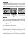
Viewing conditions affect what you can see through your telescope during an observing session. Conditions include
transparency, sky illumination, and seeing. Understanding viewing conditions and the effect they have on observing
will help you get the most out of your telescope.
Transparency
Transparency is the clarity of the atmosphere which is affected by clouds, moisture, and other airborne particles.
Thick cumulus clouds are completely opaque while cirrus can be thin, allowing the light from the brightest stars
through. Hazy skies absorb more light than clear skies making fainter objects harder to see and reducing contrast on
brighter objects. Aerosols ejected into the upper atmosphere from volcanic eruptions also affect transparency. Ideal
conditions are when the night sky is inky black.
Sky Illumination
General sky brightening caused by the Moon, aurorae, natural airglow, and light pollution greatly affect
transparency. While not a problem for the brighter stars and planets, bright skies reduce the contrast of extended
nebulae making them difficult, if not impossible to see. To maximize your observing, limit deep sky viewing to
moonless nights far from the light polluted skies found around major urban areas. LPR filters enhance deep sky
viewing from light polluted areas by blocking unwanted light while transmitting light from certain deep sky objects.
You can, on the other hand, observe planets and stars from light polluted areas or when the Moon is out.
Seeing
Seeing conditions refers to the stability of the atmosphere and directly affects the amount of fine detail seen in
extended objects. The air in our atmosphere acts as a lens which bends and distorts incoming light rays. The
amount of bending depends on air density. Varying temperature layers have different densities and, therefore, bend
light differently. Light rays from the same object arrive slightly displaced creating an imperfect or smeared image.
These atmospheric disturbances vary from time-to-time and place-to-place. The size of the air parcels compared to
your aperture determines the "seeing" quality. Under good seeing conditions, fine detail is visible on the brighter
planets like Jupiter and Mars, and stars are pinpoint images. Under poor seeing conditions, images are blurred and
stars appear as blobs.
The conditions described here apply to both visual and photographic observations.
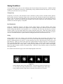
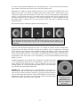
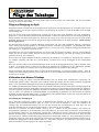
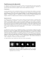
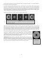
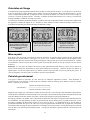
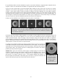
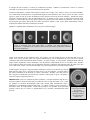
Figure 5-3
Seeing conditions directly affect image quality. These drawings represent a point source
(i.e., star) under bad seeing conditions (left) to excellent conditions (right). Most often,
seeing conditions produce images that lie somewhere between these two extremes.

20
The PowerSeeker series of telescopes was designed for visual observing. After looking at the night sky for a while
you may want to try your hand at photography of it. There are a few simple forms of photography possible with your
60AZ, 70AZ and 76AZ telescope for celestial as well as terrestrial pursuits although celestial photography is best
done using an equatorial mount or computerized altazimuth mount. Below is just a very brief discussion of some of
the methods of photography available and suggest you search out various books for detailed information on the
subject matter.
As a minimum you will need a digital camera or a 35mm SLR camera. Attach your camera to the telescope with:
y Digital camera – you will need the Universal Digital Camera Adapter (# 93626). The adapter allows the
camera to be mounted rigidly for terrestrial as well as prime focus astrophotography.
y 35mm SLR camera – you will need to remove your lens from the camera and attach a T-Ring for your
specific camera brand. Then, you will need a T-Adapter (# 93625) to attach on one end to the T-Ring and
the other end to the telescope focus tube. Your telescope is now the camera lens.
S
S
h
h
o
o
r
r
t
t
E
E
x
x
p
p
o
o
s
s
u
u
r
r
e
e
P
P
r
r
i
i
m
m
e
e
F
F
o
o
c
c
u
u
s
s
P
P
h
h
o
o
t
t
o
o
g
g
r
r
a
a
p
p
h
h
y
y
Short exposure prime focus photography is the best way to begin imaging celestial objects. It is done by attaching
your camera to the telescope as described in the paragraph above. A couple of points to keep in mind:
y You can image the Moon as well as the brighter planets with very short exposures. You will have to
experiment with various settings and exposure times. Much information can be obtained from your camera
instruction manual which can supplement what you can find in detailed books on the subject matter.
y Do your photography from a dark sky observing site if possible.
y Remember, this is just very simple photography. For more detailed and serious astrophotography you need
an equatorial mount or a computerized altazimuth mount.
P
P
l
l
a
a
n
n
e
e
t
t
a
a
r
r
y
y
&
&
L
L
u
u
n
n
a
a
r
r
P
P
h
h
o
o
t
t
o
o
g
g
r
r
a
a
p
p
h
h
y
y
w
w
i
i
t
t
h
h
S
S
p
p
e
e
c
c
i
i
a
a
l
l
I
I
m
m
a
a
g
g
e
e
r
r
s
s
During the last few years a new technology has evolved which makes taking superb images of the planets and moon
relatively easy and the results are truly amazing. Celestron offers the NexImage (# 93712) which is a special camera
and included is software for image processing. You can capture planetary images your first night out which rivals
what professionals were doing with large telescopes just a few short years ago.
C
C
C
C
D
D
I
I
m
m
a
a
g
g
i
i
n
n
g
g
f
f
o
o
r
r
D
D
e
e
e
e
p
p
-
-
S
S
k
k
y
y
O
O
b
b
j
j
e
e
c
c
t
t
s
s
Special cameras have been developed for taking images of deep sky images. These have evolved over the last
several years to become much more economical and amateurs can take fantastic images. Several books have been
written on how to get the best images possible. The technology continues to evolve with better and easier to use
products on the market.
T
T
e
e
r
r
r
r
e
e
s
s
t
t
r
r
i
i
a
a
l
l
P
P
h
h
o
o
t
t
o
o
g
g
r
r
a
a
p
p
h
h
y
y
Your telescope makes an excellent telephoto lens for terrestrial (land) photography. You can take images of various
scenic views, wildlife, nature, and just about anything. You will have to experiment with focusing, speeds, etc. to
get the best image desired. You can adapt your camera per the instructions at the top of this page.

21
While your telescope requires little maintenance, there are a few things to remember that will ensure your telescope
performs at its best.
C
C
a
a
r
r
e
e
a
a
n
n
d
d
C
C
l
l
e
e
a
a
n
n
i
i
n
n
g
g
o
o
f
f
t
t
h
h
e
e
O
O
p
p
t
t
i
i
c
c
s
s
Occasionally, dust and/or moisture may build up on the objective lens or primary mirror depending on which type of
telescope you have. Special care should be taken when cleaning any instrument so as not to damage the optics.
If dust has built up on the optics, remove it with a brush (made of camel’s hair) or a can of pressurized air. Spray at an
angle to the glass surface for approximately two to four seconds. Then, use an optical cleaning solution and white tissue
paper to remove any remaining debris. Apply the solution to the tissue and then apply the tissue paper to the optics. Low
pressure strokes should go from the center of the lens (or mirror) to the outer portion. Do NOT rub in circles!
You can use a commercially made lens cleaner or mix your own. A good cleaning solution is isopropyl alcohol mixed
with distilled water. The solution should be 60% isopropyl alcohol and 40% distilled water. Or, liquid dish soap diluted
with water (a couple of drops per one quart of water) can be used.
Occasionally, you may experience dew build-up on the optics of your telescope during an observing session. If you want
to continue observing, the dew must be removed, either with a hair dryer (on low setting) or by pointing the telescope at
the ground until the dew has evaporated.
If moisture condenses on the inside of the optics, remove the accessories from the telescope. Place the telescope in a dust-
free environment and point it down. This will remove the moisture from the telescope tube.
To minimize the need to clean your telescope, replace all lens covers once you have finished using it. Since the cells are
NOT sealed, the covers should be placed over the openings when not in use. This will prevent contaminants from entering
the optical tube.
Internal adjustments and cleaning should be done only by the Celestron repair department. If your telescope is in need of
internal cleaning, please call the factory for a return authorization number and price quote.
C
C
o
o
l
l
l
l
i
i
m
m
a
a
t
t
i
i
o
o
n
n
o
o
f
f
a
a
N
N
e
e
w
w
t
t
o
o
n
n
i
i
a
a
n
n
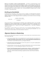
The optical performance of most Newtonian reflecting telescopes can be optimized by re-collimating (aligning) the
telescope's optics, as needed. To collimate the telescope simply means to bring its optical elements into balance. Poor
collimation will result in optical aberrations and distortions.
Before collimating your telescope, take time to familiarize yourself with all its components. The primary mirror is the
large mirror at the back end of the telescope tube. This mirror is adjusted by loosening and tightening the three screws,
placed 120 degrees apart, at the end of the telescope tube. The secondary mirror (the small, elliptical mirror under the
focuser, in the front of the tube) also has three adjustment screws (you will need optional tools (described below) to
perform collimation. To determine if your telescope needs collimation first point your telescope toward a bright wall or
blue sky outside.
Aligning the Secondary Mirror
The following describes the procedure for daytime collimation of your telescope using the optional Newtonian
Collimation Tool (#94183) offered by Celestron. To collimate the telescope without the Collimation Tool, read the
following section on night time star collimation. For very precise collimation, the optional Collimation Eyepiece 1 ¼”
(# 94182) is offered.
If you have an eyepiece in the focuser, remove it. Rack the focuser tube in completely, using the focusing knobs, until its
silver tube is no longer visible. You will be looking through the focuser at a reflection of the secondary mirror, projected
from the primary mirror. During this step, ignore the silhouetted reflection from the primary mirror. Insert the collimating
cap into the focuser and look through it. With the focus pulled in all the way, you should be able to see the entire primary
mirror reflected in the secondary mirror. If the primary mirror is not centered in the secondary mirror, adjust the
secondary mirror screws by alternately tightening and loosening them until the periphery of the primary mirror is centered
in your view. DO NOT loosen or tighten the center screw in the secondary mirror support, because it maintains proper
mirror position.
Page is loading ...
Page is loading ...
Page is loading ...
Page is loading ...
Page is loading ...
Page is loading ...
Page is loading ...
Page is loading ...
Page is loading ...
Page is loading ...
Page is loading ...
Page is loading ...
Page is loading ...
Page is loading ...
Page is loading ...
Page is loading ...
Page is loading ...
Page is loading ...
Page is loading ...
Page is loading ...
Page is loading ...
Page is loading ...
Page is loading ...
Page is loading ...
Page is loading ...
Page is loading ...
Page is loading ...
Page is loading ...
Page is loading ...
Page is loading ...
Page is loading ...
Page is loading ...
Page is loading ...
Page is loading ...
Page is loading ...
Page is loading ...
Page is loading ...
Page is loading ...
Page is loading ...
Page is loading ...
Page is loading ...
Page is loading ...
Page is loading ...
Page is loading ...
Page is loading ...
Page is loading ...
Page is loading ...
Page is loading ...
Page is loading ...
Page is loading ...
Page is loading ...
Page is loading ...
Page is loading ...
Page is loading ...
Page is loading ...
Page is loading ...
Page is loading ...
Page is loading ...
Page is loading ...
Page is loading ...
Page is loading ...
Page is loading ...
Page is loading ...
Page is loading ...
Page is loading ...
Page is loading ...
Page is loading ...
Page is loading ...
Page is loading ...
Page is loading ...
Page is loading ...
Page is loading ...
Page is loading ...
Page is loading ...
Page is loading ...
Page is loading ...
Page is loading ...
Page is loading ...
Page is loading ...
Page is loading ...
Page is loading ...
Page is loading ...
Page is loading ...
Page is loading ...
Page is loading ...
Page is loading ...
Page is loading ...
Page is loading ...
Page is loading ...
Page is loading ...
Page is loading ...
Page is loading ...
Page is loading ...
Page is loading ...
Page is loading ...
Page is loading ...
Page is loading ...
Page is loading ...
Page is loading ...
Page is loading ...
Page is loading ...
Page is loading ...
Page is loading ...
Page is loading ...
Page is loading ...
-
 1
1
-
 2
2
-
 3
3
-
 4
4
-
 5
5
-
 6
6
-
 7
7
-
 8
8
-
 9
9
-
 10
10
-
 11
11
-
 12
12
-
 13
13
-
 14
14
-
 15
15
-
 16
16
-
 17
17
-
 18
18
-
 19
19
-
 20
20
-
 21
21
-
 22
22
-
 23
23
-
 24
24
-
 25
25
-
 26
26
-
 27
27
-
 28
28
-
 29
29
-
 30
30
-
 31
31
-
 32
32
-
 33
33
-
 34
34
-
 35
35
-
 36
36
-
 37
37
-
 38
38
-
 39
39
-
 40
40
-
 41
41
-
 42
42
-
 43
43
-
 44
44
-
 45
45
-
 46
46
-
 47
47
-
 48
48
-
 49
49
-
 50
50
-
 51
51
-
 52
52
-
 53
53
-
 54
54
-
 55
55
-
 56
56
-
 57
57
-
 58
58
-
 59
59
-
 60
60
-
 61
61
-
 62
62
-
 63
63
-
 64
64
-
 65
65
-
 66
66
-
 67
67
-
 68
68
-
 69
69
-
 70
70
-
 71
71
-
 72
72
-
 73
73
-
 74
74
-
 75
75
-
 76
76
-
 77
77
-
 78
78
-
 79
79
-
 80
80
-
 81
81
-
 82
82
-
 83
83
-
 84
84
-
 85
85
-
 86
86
-
 87
87
-
 88
88
-
 89
89
-
 90
90
-
 91
91
-
 92
92
-
 93
93
-
 94
94
-
 95
95
-
 96
96
-
 97
97
-
 98
98
-
 99
99
-
 100
100
-
 101
101
-
 102
102
-
 103
103
-
 104
104
-
 105
105
-
 106
106
-
 107
107
-
 108
108
-
 109
109
-
 110
110
-
 111
111
-
 112
112
-
 113
113
-
 114
114
-
 115
115
-
 116
116
-
 117
117
-
 118
118
-
 119
119
-
 120
120
-
 121
121
-
 122
122
-
 123
123
-
 124
124
-
 125
125
-
 126
126


Ask a question and I''ll find the answer in the document
Finding information in a document is now easier with AI
in other languages
- italiano: Celestron 21041 Manuale del proprietario
- français: Celestron 21041 Le manuel du propriétaire
- español: Celestron 21041 El manual del propietario
- Deutsch: Celestron 21041 Bedienungsanleitung
Related papers
-
Celestron PowerSeeker 50AZ User manual
-
Celestron 21035 Owner's manual
-
-
-
Celestron PowerSeeker User manual
-
Celestron PowerSeeker 50 Quick Setup
-
-
-
Celestron PowerSeeker 76 User manual
-
Other documents
-
Tasco Spacestation 49076525/49114675 User manual
-
Sharper Image Backpack Telescope Owner's manual
-
Barska Telescope Basics Owner's manual
-
National Geographic 9065000 Owner's manual
-
National Geographic 9015000 Owner's manual
-
ISA 4541009 Owner's manual
-
NATURE & DECOUVERTES 53151590 Operating instructions
-
 Sky Watcher S11620 User manual
-
Elenco EDU41010 Owner's manual
-
Bresser Junior 8850900 Owner's manual
