Page is loading ...

DVM831
31.03.2010 2 ©Velleman nv
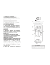
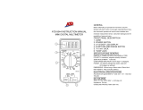
1 DISPLAY 1
DISPLAY
2 FUNCTION AND RANGE
SWITCH
2
FUNCTIE- en
BEREIKSCHAKELAAR
3 "10A" JACK 3
"10A" AANSLUITING
4 "VmA" JACK 4
"VΩmA" AANSLUITING
5 "Common" JACK 5
"10A" AANSLUITING
1 AFFICHEU
R
1
PANTALLA
2 S
É
LECTEUR de FONCTION et de
PLAGE
2
SELECTOR de FUNCI
Ó
N y de
RANGO
3 CONNEXION "10A" 3
CONEXI
Ó
N "10A"
4 CONNEXION 4
CONEXI
Ó
N "VΩmA"
5 Common 5
CONEXI
Ó
N "Common
1 DISPLAY
2 FUNKTIONS- und
BEREICHSSCHALTER
3 10A-BUCHSE
4
VΩmA-BUCHSE
5 Common-BUCHSE

31.03.2010
1. Introdu
c
To all reside
n
Im
p
Thi
s
the
dis
p
sh
o
sh
o
Re
s
If in doubt, c
o
Please read th
e
If the device
w
Dama
g
e cause
by the warran
t
defects or pro
b
The DVM831
i
device is suita
b
resistance, co
n
Be extremly c
a
even fatal in
j
u
r
workin
g
with c
mentioned in t
circuits or test
This device is
n
Refer to the V
e
this manual.
2. Used sy
m
This
Not r
e
deat
h
This
A ha
z
This
Risk
o
in
j
ur
y
This
I
g
no
r
AC (
A
DC (
D
Doub
Eart
h
USE
R
c
tion
n
ts of the European
p
ortant environmenta
s
symbol on the devi
c
device after its lifecy
p
ose of the unit (or b
a
o
uld be taken to a spe
o
uld be returned to yo
s
pect the local enviro
n
o
ntact your local w
a
e
manual thorou
g
hly
b
w
as dama
g
ed in transi
t
d by disre
g
ard of cer
t
t
y and the dealer will
b
lems.
i
s a CAT II - 500V di
g
b
le for measurin
g
dir
e
n
tinuity, diodes and tr
a
utious when usin
g
th
r
ies. Apart from the u
ircuits the user must
his manual. Do not
u
procedures!
n
ot suitable for comm
e
lleman® Service a
n
m
bols
symbol indicates:
R
e
adin
g
the instructio
n
h
.
symbol indicates:
D
z
ardous condition or
a
symbol indicates:
R
o
f a hazardous condit
y
or death
symbol indicates:
A
r
in
g
this information
c
A
lternatin
g
Current)
D
irect Current)
le insulation (class II
-
h
DVM831
3
R
MANUAL
Union
l information about t
h
c
e or the packa
g
e indi
cle could harm the e
n
a
tteries) as unsorted
m
cialized company for
ur distributor or to a
l
n
mental rules.
a
ste disposal auth
o
b
efore brin
g
in
g
this d
e
t
, do not use it and c
o
t
ain
g
uidelines in this
not accept responsibi
l
ital multi meter with
a
e
ct and alternatin
g
vo
l
ansistors.
is device: carelessne
s
sual safety precautio
n
comply to the safety
u
se this device when
y
ercial or industrial us
e
n
d
Q
uality Warrant
y
R
ead instructions
n
s and manual can le
a
D
an
g
er
a
ction that may result
R
isk of dan
g
er/dam
ion or action that ma
y
A
ttention; importan
t
c
an lead to hazardous
-
protection)
©Velleman n
v
h
is product
cates that disposal of
n
vironment. Do not
m
unicipal waste; it
recyclin
g
. This device
l
ocal recyclin
g
servic
e
o
rities.
e
vice into service.
o
ntact your dealer.
manual is not covere
d
l
ity for any ensuin
g
a
3 ½ digit LCD; this
l
ta
g
es and currents,
s
s can lead to serious
n
s applicable when
precautions as
y
ou are unfamiliar wit
h
e
.
y
on the last pa
g
es o
f
a
d to dama
g
e, in
j
ury
o
in in
j
ury or death
a
g
e
y
result in dama
g
e,
t
information
situations.
v
e
.
d
or
h
f
o
r

31.03.2010
Fuse
Diod
e
Conti
3. Warnin
g
Read
the d
Only
unau
t
of ce
r
the d
probl
Follo
w
all its
Durin
g
a
g
ain
s
WAR
N
To av
o
To pr
e
Rem
a
Keep
t
Prote
c
opera
t
Avoid
move
d
reach
e
error
s
This
i
instr
u
indica
Pollut
i
from
r
use.
R
Befo
r
Alwa
y
prob
e
conn
e
Make
conn
e
Risk
o
meas
u
hi
g
he
r
e
nuity
g
s and safety ins
t
this manual thorou
gh
evice before actually
use the device for its
t
horized way will void
r
tain
g
uidelines in thi
s
ealer will not accept
r
ems.
w
the instructions bel
o
functionalities.
g
use of the meter, r
e
s
t electroshocks and
m
N
ING:
o
id electrical shock r
e
e
vent fire, only install
a
rk: refer to the warn
t
he device away from
c
t this device from sh
o
t
in
g
.
cold, heat and lar
g
e
t
d
from a cold to a wa
r
e
d room temperature
s
.
i
s an installation ca
t
u
ment. Never use th
ted. Refer to §4 Ove
r
i
on de
g
ree 2-device.
F
r
ain, moisture, splash
R
efer to §5 Pollutio
n
r
e each use, make su
r
y
s place your fin
g
ers
b
e
s while measurin
g
!
N
e
cted to a circuit.
sure the meter is in
t
e
ctin
g
it to a test circ
u
o
f electric shock du
u
rin
g
live circuits. Us
e
r
than 60Vdc or 30Va
c
DVM831
4
t
ructions
h
ly. Familiarise yours
e
usin
g
it.
intended purpose. U
s
the warranty. Dama
g
s
manual is not cover
e
r
esponsibility for any
e
o
w to
g
uarantee a saf
e
e
spect all directives c
o
m
isuse. Never exceed
e
move test leads befo
r
fuses with AMP/VOL
T
in
g
on the back of th
e
children and unauth
o
o
cks and abuse. Avoi
d
t
emperature fluctuati
o
r
m location, leave it s
. This to avoid conde
n
t
e
g
ory CAT II 500
V
is equipment in a hi
g
r
volta
g
e /installati
o
F
or indoor use only.
K
in
g
and drippin
g
liqui
d
n
de
g
ree.
r
e the test probes are
b
ehind the protective
N
ever touch free ter
m
t
he appropriate meas
u
it.
rin
g
operation. Be
v
e
extreme caution wh
e
c
rms.
©Velleman n
v
e
lf with the functions
o
s
in
g
the device in an
g
e caused by disre
g
a
r
e
d by the warranty a
n
e
nsuin
g
defects or
e
use of the meter an
d
o
ncernin
g
protection
the indicated limits.
r
e opening the device
T
ratin
g
shown.
e
mete
r
.
o
rised users.
d
brute force when
o
ns. When the unit is
witched off until it ha
n
sation and measurin
g
V
measurin
g
her cate
g
ory than
o
n cate
g
ory.
K
eep this device away
d
s. Not for industrial
in
g
ood condition.
ed
g
es of the test
m
inals when the mete
r
urin
g
ran
g
e before
v
ery careful when
e
n measurin
g
volta
g
e
v
o
f
r
d
n
d
d
s
g
r
is
s

31.03.2010
Do n
o
Do n
o
Do n
o
circui
When
meas
u
meas
u
When
circui
t
point
s
Do n
acce
s
acce
s
Swit
c
batte
All m
Dam
a
the
w
4. Overvol
t
DMMs are cat
e
overvolta
g
e th
a
bursts of ener
g
line.
The existin
g
c
a
CAT I
A CAT I
circuits
circuits
,
CAT
II
A CAT I
environ
mains
b
provide
apart f
r
tools…
CAT
III
A CAT I
environ
phased
environ
(fuse b
o
CAT
IV
A CAT I
CAT III
-
Note th
run out
d
used.
Warning:
This device wa
CAT II 500V.
T
o
t measure circuits th
o
t measure current in
o
t conduct resistance,
ts.
measurin
g
currents
u
u
rement followed by
a
u
rements.
carryin
g
out measur
e
t
s, always be aware t
h
s
mi
g
ht dama
g
e the
m
ot replace internal p
a
s
sories by identical on
s
sories e.
g
. test prob
e
c
h off the meter and r
e
ry or fuses.
odifications of the de
v
ag
e caused by user m
w
arranty.
t
age/installatio
n
eg
orized dependin
g
o
n
a
t mi
g
ht occur at the
g
y induced in a syste
m
a
te
g
ories accordin
g
E
N
-rated meter is suita
b
which are not directl
y
,
control si
g
nals…
I-rated meter is suita
ments and mono-pha
b
y means of a plu
g
an
d that the circuit is a
t
r
om a CAT IV-environ
m
II-rated meter is suit
a
ments, as well as for
appliances which are
ment, and for measu
r
o
xes, li
g
htin
g
circuits,
V-rated meter is suit
a
-
environments as wel
at for all measureme
n
d
oors (either overhea
s desi
g
ned in accord
a
T
his implies that certa
DVM831
5
at may contain volta
g
circuits with volta
g
e
s
diode- or continuity
m
u
p to 10A, max. 10s
c
a
15 minutes break b
e
e
ments on a TV set o
r
h
at hi
g
h amplitude v
o
m
eter.
a
rts yourself. Replace
es with the same spe
e
s at your dealer.
e
move test probes pr
v
ice are forbidden for
odifications to the de
v
n
category
n
the risk and severit
y
point of test. Transie
n
m
, e.
g
. caused by li
g
h
N
61010-1 are:
b
le for measurements
y
connected to mains
ble for measurement
s
se appliances which
a
d circuits in a normal
t
least 10m apart fro
m
m
ent. E.
g
. household
a
ble for measuremen
t
measurements on (fi
x
at least 10m apart fr
r
ements in or on dist
r
electric ovens).
a
ble for measurin
g
in
l as on the primary s
u
n
ts on equipment for
w
d or under
g
round) a
C
a
nce with EN 61010-1
in restrictions in use
a
©Velleman n
v
g
es > 500V
s
> 250V
m
easurements on liv
e
c
ontinuous
e
tween 2
r
switchin
g
power
o
lta
g
e pulses at the te
dama
g
ed or lost
cifications. Order spa
r
ior to replacin
g
the
safety reasons.
v
ice is not covered b
y
y
of transient
n
ts are short-lived
tnin
g
strike on a pow
e
on protected electro
n
power, e.
g
. electroni
c
s
in CAT I-
a
re connected to the
domestic environme
n
m
a CAT III- or 20m
appliances, portable
t
s in CAT I- and CAT
I
x
ed) mono- or poly-
om of a CAT IV-
r
ibution level equipm
e
CAT I-, CAT II- and
u
pply level.
w
hich the supply cabl
C
AT IV meter must
b
installation cate
g
ory
a
pply that are related
v
e
st
r
e
y
e
r
n
ic
c
s
n
t,
I
I-
e
nt
es
b
e

31.03.2010
to volta
g
es an
d
Refer to the ta
This device i
s
• Protected el
e.g. electro
n
• circuits whi
c
• measure
m
mains b
y
• mono-ph
normal d
apart fro
m
househol
a distrib
u
This device i
s
• Volta
g
es ab
o
• measureme
behind
met
e
• measureme
CAT III or
C
circuits, bu
s
• Measureme
n
meter boxe
s
environmen
or circuits u
Thi
s
en
v
5. Pollutio
n
IEC 61010-1 s
p
different prote
c
environments
r
which is to be
f
and the enclos
which environ
m
Pollution
degree 1
No
po
l
en
c
Pollution
degree 2
On
co
n
off
i
Pollution
degree 3
Co
n
th
a
(in
bu
t
Pollution
degree 4
Th
e
du
s
en
v
fin
e
d
volta
g
e peaks whic
h
ble above.
s
suitable for meas
u
ectronic circuits whic
h
n
ics circuits, control s
c
h are directly connec
m
ents on mono-phas
e
y
means of a plu
g
ase appliances and ci
omestic environment
,
m
a CAT III- or 20m
a
d appliances, portabl
e
u
tion board …
s
NOT suitable for:
o
ve 500V
nts in/on low-volta
g
e
e
r box)
nts on (fixed) mono-
C
AT IV environments
(
s
bars, low-voltage di
s
n
ts on distribution eq
u
s
and equipment/circ
u
t e.
g
. circuits in shed
s
sin
g
under
g
round wir
s
device is only suita
b
v
ironments.
n
degree
p
ecifies different typ
e
c
tive measures are n
e
r
equire more protecti
o
f
ound in a certain en
v
ure properties. The p
o
m
ent the device may
b
pollution or only dry,
l
lution has no influen
c
c
losures).
ly nonconductive poll
u
n
ductivity caused by
c
i
ce environments fall
n
ductive pollution oc
c
a
t becomes conductiv
e
dustrial environment
s
t
not in contact with
p
e
pollution
g
enerates
s
t or by rain or snow.
v
ironments where hi
g
e
particles occur)
DVM831
6
h
can occur within the
u
rements up to 500
V
h
are not directly con
n
i
g
nals, circuits behin
d
ted to mains power,
b
e
appliances which ar
e
rcuits directly connec
t
,
provided that the ci
r
a
part from a CAT IV-
e
e
tools, li
g
ht circuits
a
distribution boards (
d
or poly-phased appli
a
(
e.
g
. mains outlets, el
s
tribution boards and
u
ipment and outdoor
u
its outside or remot
e
s
,
g
arden houses and
in
g
e.
g
.
g
arden li
g
hti
n
b
le for measurements
e
s of pollution environ
e
cessary to ensure sa
f
o
n, and the protectio
n
v
ironment depends m
a
o
llution de
g
ree ratin
g
b
e used.
nonconductive pollu
t
c
e (only to be found i
n
u
tion occurs. Occasio
n
c
ondensation is to be
under this cate
g
ory).
c
urs, or dry noncondu
c
e
due to condensatio
n
s
and environments e
x
p
recipitation).
persistent conductivi
t
(exposed outdoor en
h humidity levels or
h
©Velleman n
v
environment of use.
V
on:
n
ected to mains pow
e
d
isolatin
g
transforme
r
b
ut limited to:
e
connected to the
t
ed to the mains in a
r
cuit is at least 10m
e
nvironment. E.
g
.
a
t more than 10m fro
m
d
istribution boards
a
nces and circuits in
ectric ovens, li
g
htin
g
circuit breakers).
installations includin
g
e
from the domestic
free-standin
g
g
ara
ge
ng
, pool-pump...
up to 500V in CAT
I
ments, for which
f
ety. Harsher
n
a
g
ainst the pollutio
n
a
inly on the insulatio
n
of the DVM indicates
t
ion occurs. The
n
hermetically sealed
n
ally, temporary
expected (home and
c
tive pollution occurs
n
that is to be expect
e
x
posed to outside air
t
y caused by conducti
v
vironments and
h
i
g
h concent
r
ations o
f
v
e
r,
r
…
m
g
e
s,
I
I
n
n
in
e
d
-
v
e
f

31.03.2010
Warning:
This device wa
This implies th
which can occ
u
This
d
de
g
r
e
6. Descrip
t
Refer to the ill
u
Selection swi
Always
r
function
o
To switc
h
"10A" JACK:
"COM" JACK:
"VmA" JAC
K
7. Operati
n
Risk
mea
s
Befo
r
not
d
• Never exce
e
separately i
• Do not touc
bein
g
teste
d
• Only use th
e
measure vo
• Disconnect
t
selector in
o
• When carry
i
always rem
e
dama
g
e th
e
• Always be c
Keep your f
i
• Do not mea
• Never perfo
Make sure
a
• When the d
i
is hi
g
her th
a
• When a low
readin
g
alt
h
normal and
and
g
ive a
p
s desi
g
ned in accord
a
at certain restrictions
u
r within the environ
m
d
evice is only suita
b
e
e class 2 environm
e
t
ion of the Front
u
stration on pa
g
e 2 o
f
tch: the meter has
m
selected via the
r
emove the test prob
e
o
r ran
g
e!
h
off the meter, set th
Connect the red te
s
> 200mA
Connect the black
t
K
: Connect the red te
s
except current me
a
n
g instructions
of electric shock d
u
s
urin
g
live circuits.
r
e measurin
g
, always
d
ama
g
ed and verify t
h
e
d the limit value for
p
n the specifications f
o
h unused terminals w
d
.
e
meter in the indicat
e
lta
g
es that mi
g
ht exc
e
t
he test leads from th
o
rder to chan
g
e functi
i
n
g
out measurement
s
e
mber that hi
g
h ampl
e
meter.
areful when workin
g
w
i
n
g
ers behind the pro
sure current in circuit
rm resistance, diode
o
a
ll capacitors in the ci
r
i
splay indicates "OL"
d
a
n the currently man
u
volta
g
e ran
g
e is sele
c
h
ou
g
h the leads are n
o
is caused by the hi
gh
p
roper measurement
w
DVM831
7
a
nce with EN 61010-1
in use apply that are
m
ent of use. Refer to
t
b
le for measureme
n
e
nts.
Panel
f
this manual.
m
ultiple functions and
selection switch.
e
s from the ciruit bef
o
e selection switch to
O
s
t lead to this
j
ack fo
r
t
est lead to this
j
ack
s
t lead to this
j
ack fo
r
a
surements > 200mA
u
rin
g
operation. Be
make sure the meter
h
e connections, select
e
p
rotection. This limit
v
o
r each ran
g
e of mea
s
hen the meter is link
e
e
d overvolta
g
e/install
e
ed the indicated cat
e
e tested circuit befor
e
ons.
s
on a TV set or switc
itude volta
g
e pulses
a
w
ith volta
g
es above
6
be barriers at all tim
e
s with volta
g
es > 25
0
o
r continuity measur
e
r
cuit are dischar
g
ed.
d
urin
g
a measuremen
u
ally selected ran
g
e.
S
c
ted, the display may
o
t connected to a dev
h
input sensitivity. Th
e
w
hen connected to a
c
©Velleman n
v
pollution degree 2
.
related to pollution
t
he table above.
n
ts in Pollution
ran
g
es that can be
o
re selecting a differe
n
O
FF.
r
current measureme
n
r
all measurements
very careful when
and/or test probes a
r
e
d function and ran
ge
v
alue is listed
s
urement.
e
d to a circuit which i
s
ation cate
g
ory. Neve
r
eg
ory values.
e
rotatin
g
the ran
g
e
hin
g
power circuits,
a
t the test points mi
gh
6
0Vdc or 30Vac rms.
e
s durin
g
measureme
n
0
V
e
ments on live circuit
s
t, the measured valu
e
S
elect a hi
g
her ran
g
e.
show a varyin
g
ice or circuit. This is
e
readin
g
will stabilize
c
ircuit.
v
.
n
t
n
ts
r
e
e
.
s
r
h
t
n
t.
s
.
e

31.03.2010
Volta
g
e mea
s
Do n
o
Alway
s
rms.
K
meas
u
to a ci
• Connect th
e
VmA jack
• For DC volt
a
the ran
g
e i
s
appropriate
• For AC volt
a
the ran
g
e i
s
appropriate
• Connect th
e
• The measu
r
Notes:
• For D
C
test le
• When
althou
norm
a
stabili
z
Direct curren
Do no
t
This
d
not s
u
Curre
n
to 10
A
contin
meas
u
Alway
s
rms.
K
meas
u
• For measu
j
ack and th
e
500mA/250
• For measu
and the bla
c
10A/220V).
• For DC mea
desired ran
g
• For DC mea
desired ran
g
• When the r
a
to the appr
o
• Connect th
e
• Read the m
e
s
urements
o
t measure circuits
w
s
be careful when wo
r
K
eep your fin
g
ers beh
i
u
rement. Do not touc
h
rcuit which is bein
g
t
e
e
black test lead to th
e
.
ag
es, set the selector
s
unknown, always se
t
ran
g
e.
ag
es, set the selector
s
unknown, always se
t
ran
g
e.
e
test probes with the
r
ed volta
g
e is shown
o
C
-measurements: wh
e
ad, the indicated val
u
the mV ran
g
e is sele
c
g
h the probes are no
t
a
l and is caused by th
e
z
e and
g
ive a proper
m
t measurements
t
measure current in
c
d
evice is only desi
gn
u
itable for alternati
n
t measurements V
m
A
use the 10A
j
ack. W
uous measurement f
o
u
rements.
s
be careful when wo
r
K
eep your fin
g
ers beh
u
rement.
rements up to 200
m
e
black lead to the C
O
V).
rements up to 10A:
c
k lead to the COM
j
a
surements up to 200
m
g
e.
surements up to 10A
,
g
e (use the 10A
j
ack
)
a
n
g
e is unknown, alw
a
o
priate ran
g
e.
e
test probes in series
e
asured cuurent from
DVM831
8
w
here volta
g
es > 5
r
kin
g
with volta
g
es a
b
i
nd the probe barrier
s
h
unused terminals w
h
e
sted.
e
COM
j
ack and the r
e
switch to V in the
d
t
the hi
g
hest possible
switch to V in the
t
the hi
g
hest possible
circuit under test.
o
n the display.
e
n a ne
g
ative polarity
u
e is preceded by a “-
c
ted, the display may
t
connected to a devi
c
e
hi
g
h input sensitivit
y
m
easurement when c
o
c
ircuits with volta
g
es
n
ed for DC current
m
n
g
current measur
e
m
A
j
ack max. 200m
A
hen measurin
g
curre
n
o
llowed by a 15 minu
t
r
kin
g
with volta
g
es a
b
ind the probe barrier
s
m
A: connect the red t
O
M jack (protected wi
t
connect the red test
ck (protected with a
c
m
A, set the selector s
,
set the selector swit
c
)
.
a
ys set the hi
g
hest p
o
with the circuit.
the display.
©Velleman n
v
00V CAT II
b
ove 60Vdc or 30Vac
s
at all times durin
g
h
en the meter is link
e
e
d test lead to the
d
esired ran
g
e. When
ran
g
e and lower to t
h
desired ran
g
e. When
ran
g
e and lower to t
h
is present at the red
” si
g
n.
show a varyin
g
readi
n
c
e or circuit. This is
y
. The reading will
o
nnected to a circuit.
> 250V
m
easurements; it i
s
e
ments.
A
; for measurements
u
n
ts up to 10A, max. 1
t
es break between 2
b
ove 60Vdc or 30Vac
s
at all times durin
g
est lead to the Vm
A
t
h a ceramic fuse
lead to the 10A
j
ack
c
eramic fuse
witch to A in the
c
h to A in the
o
ssible ran
g
e and low
e
v
e
d
h
e
h
e
ng
s
u
p
0s
A
e
r

31.03.2010
Notes:
• For DC-c
u
red test l
• The µA a
F500mA
/
fuse.
Resistance
m
Do n
o
• Connect th
e
jack.
• Set the sel
e
unknown, a
appropriate
• Connect th
e
• The measu
r
Notes:
• Never pe
capacito
r
• To incre
a
tips of th
the test l
• For resis
t
to stabili
z
• Should t
h
open cir
c
Continuity te
s
Do n
o
• Connect th
e
VmA
j
ack
• Set the sel
e
• Connect th
e
• When the
m
produced a
n
resistance
e
will show “1
Note:
• Never pe
capacito
r
Diode test
Do n
o
• Connect th
e
VmA
j
ack
• Set the sel
e
• Connect th
e
the anode,
b
u
rrent measurement
s
ead, the indicated va
l
nd mA-ranges are pr
o
/
250V fuse; the 10A r
a
m
easurements
o
t perform resistan
c
e
red test lead to the
V
e
ction switch to the d
e
lways select the hi
g
h
e
ran
g
e.
e
test probes to the ci
r
r
ed value appears on
t
rform resistance mea
r
s are completely disc
h
a
se accuracy when m
e
e measurin
g
probes t
eads. Subtract this v
a
t
ance measurements
a
z
e the read-out.
h
e measured resistan
c
c
uit, the display will s
h
s
t
o
t perform continui
t
e
black test lead to th
e
.
e
ction switch to 200
e
test leads to the circ
m
easured resistance i
s
n
d the resistance is s
h
e
xceed the selected r
a
”.
rform continuity mea
s
r
s are completely disc
h
o
t perform diode m
e
e
black test lead to th
e
.
e
ction switch to 2000
e
test leads to the circ
b
lack test probe to th
e
DVM831
9
s
, when a ne
g
ative po
l
l
ue is preceded by a “
o
tected a
g
ainst ove
r
-
c
a
n
g
e is protected wit
h
c
e measurements o
n
V
mA
j
ack and the b
e
sired "Ω” range. Whe
e
st possible ran
g
e an
d
r
cuit/component und
e
t
he display.
surements on a live
c
h
ar
g
ed.
e
asurin
g
low resistan
c
o
g
ether to determine
a
lue from the measur
e
a
bove 1M the mete
r
c
e exceed the selecte
d
h
ow “1”.
t
y measurements o
n
e
COM
j
ack and the r
e
.
uit/component under
s
less than 50 a con
t
h
owed on the display.
a
n
g
e or in case of an
o
s
urements on a live c
h
ar
g
ed.
e
asurements on liv
e
e
COM
j
ack and the r
e
.
uit/component under
e
cathode).
©Velleman n
v
l
arity is present at th
e
-” sign.
c
urrent with a cerami
c
h
a ceramic F10A/250
n
live circuits.
lack lead to the "CO
M
n the ran
g
e is
d
lower to the
e
r test.
c
ircuit and make sure
c
e values, first hold th
the resistance value
e
d value of the circui
t
r
needs a few second
s
d
ran
g
e or in case of
a
n
live circuits.
e
d test lead to the
test.
t
inuous beep is
Should the measure
d
o
pen circuit, the displ
a
ircuit and make sure
a
e
circuits.
e
d test lead to the
test (red test probe
t
v
e
c
V
M
"
all
e
of
t
.
s
a
n
d
a
y
a
ll
t
o

31.03.2010
• The meter
w
connection
i
circuited, th
Notes:
• Never pe
capacito
r
• Measurin
Consider
Transistor te
s
Do
n
Use
• Connect th
e
VmA
j
ack
• Set the sel
e
• Determine
w
emitter, th
e
the include
d
• Connect th
e
probe to th
e
• The current
• Nota:
• Make su
r
8. Mainten
a
WAR
N
openi
AMP/
Rem
a
Do n
o
acces
s
acces
s
Switc
h
batter
y
a. General m
a
• Wipe the d
e
solvents or
a
b. Battery Re
• Replace the
Low/bad ba
t
• Remove tes
the input
j
a
c
• Switch off t
h
• Release the
compartme
n
• Replace the
specificatio
n
rechar
g
eabl
• Close the b
a
w
ill display the appro
x
i
s reversed, the mete
r
e display shows 0mV
.
rform diode measure
m
r
s are completely disc
h
g
diodes that are par
t
disconnectin
g
them
f
s
t
n
ot perform transis
t
the included transi
s
e
black test lead to th
e
.
e
ction switch to hFE.
w
hether the transisto
r
e
base and the collect
o
d
adaptor socket.
e
test probes to the d
a
e
“COM”).
g
ain hFE is shown o
n
r
e to insert the transi
s
a
nce / battery a
N
ING: To avoid elec
n
g
the device To p
r
VOLT ratin
g
shown
a
rk: refer to the wa
r
o
t replace internal pa
r
s
ories by identical on
e
s
ories e.
g
. test probe
s
h
off the meter and re
y
or fuses.
a
inenance:
e
vice re
g
ularly with a
m
a
brasive products.
placement
battery as soon as t
h
t
teries can produce f
a
t probes from the cir
c
c
ks.
h
e multi-meter.
screw at the back of
n
t.
battery by 2 new ba
t
n
s followin
g
the indic
a
e batteries)
a
ttery compartment a
DVM831
10
x
imate forward volta
ge
r
will display “1
”
; if t
h
.
m
ents on a live circui
t
h
ar
g
ed.
t
of a circuit mi
g
ht pr
o
f
rom the circuit.
t
or test on live circ
u
s
tor socket.
e
COM
j
ack and the r
e
r
is of the NPN- or PN
P
o
r. Insert the leads in
t
a
ptor socket (red pro
b
n
the display (base cu
s
tor in the socket the
nd fuse replace
m
trical shock remov
e
r
event fire, only ins
t
.
r
nin
g
on the back o
f
r
ts yourself. Replace
d
e
s with the same spe
c
s
at your dealer.
move test leads prior
m
oist, lint-free cloth.
h
e “ ” indication ap
a
lse readin
g
s.
c
uit under test. Remo
v
the meter (top) and
o
t
teries of the same ty
p
a
ted polarity(2x 1.5V
A
nd ti
g
hten the screw.
©Velleman n
v
e
drop. If the lead
h
e diode is short-
t
and make sure all
o
duce faulty results.
u
its.
e
d test lead to the
P
-type and locate the
t
o the proper holes in
b
e to the “+”, black
rrent 10µA, Vce 2,8V
)
ri
g
ht way.
m
ent
e
test leads before
t
all fuses with
f
the meter.
d
ama
g
ed or lost
c
ifications. Order spar
e
to replacin
g
the
Do not use alcohol,
pears on the display.
v
e all test leads from
o
pen the battery
p
e and with the same
A
AA, do not use
v
)
.
e

31.03.2010
C. Fuse Repl
a
• The fuse ra
r
caused by a
• Remove tes
the input
j
a
c
• Switch off t
h
• Release the
compartme
n
• Release the
other 2 scr
e
• Gently rem
o
• Remove th
e
same type
a
200mA ran
g
10A range:
• Close the m
Notes:
o Do not t
r
o Never op
o Every re
p
9. Accesso
r
Check
r
test pr
o
Only u
s
Order
s
o Set test l
o Adaptor
s
o Battery (
o User ma
n
10. Specifi
This device is
n
Re
g
ulations co
• Use this me
§4)
• Use this me
Ideal tempera
t
Ideal relative
h
Max. altitude
Overvolta
g
e/i
n
Pollution de
g
r
e
Operatin
g
tem
Polarity indica
t
Overran
g
e ind
i
Low battery in
d
Measurin
g
spe
e
display
power supply
Dimensions
Weight
a
cement
r
ely needs to be repla
human erro
r
.
t probes from the cir
c
c
ks.
h
e multi-meter.
screw at the back of
n
t.
screw under the batt
e
ws on the back of th
e
o
ve the housin
g
.
e
fuse from the fuse h
o
a
nd with the same sp
e
g
e: ceramic fuse 5x2
0
ceramic fuse 5x20m
m
eter carefully but fir
m
r
y to repair or calibrat
en the housin
g
when
p
air must be perform
e
r
ies
r
e
g
ularly and before
e
o
bes for damage.
s
e accessories with th
e
s
pare accessories at y
o
eads with probe, dou
s
ocket for transistor t
e
inside meter)
n
ual
cations
n
ot calibrated when p
u
ncernin
g
environmen
t
ter only for measure
m
ter only in a pollution
t
ure
h
umidity
n
stallation cate
g
ory
e
e
perature
t
ion
i
cation
d
ication
e
d
DVM831
11
ced and a blown fuse
c
uit under test. Remo
v
the meter (top) and
o
ery compartment cov
e
meter as well.
o
lder and replace it
w
e
cifications:
0
mm F500mA/250V
m
F10A/250V
m
ly before usin
g
.
e the meter yourself.
the meter is connect
e
e
d by a trained techni
e
ach use the device a
n
e
same specifications
o
ur dealer.
ble insulated 10A CA
T
e
st
u
rchased!
t
of use:
m
ents in CAT I and C
A
de
g
ree 2 environme
n
23°C± 5°C
45%~75% RH
2000m
500V CAT II
Pollution degree 2
0°C~40°C
‘-’ automatic indicati
o
‘1’
2~3 samples per se
c
3 ½ digit LCD
2 x AAA 1.5V-batteri
rechar
g
eable batteri
e
126 x 70 x 27 (H x
B
± 170g
©Velleman n
v
is almost always
v
e all test leads from
o
pen the battery
er and release the
w
ith a new fuse of the
e
d to a live circuit.
cian.
n
d/or accessories e.
g
.
as the ori
g
inal ones.
T
III 1000V
A
T II environments (s
e
n
t (see §5)
o
n
c
ond, nominal
es (do not use
e
s
B
x D)
v
e
e

31.03.2010
fuses
200m
A
10A r
a
Max. volta
g
e
b
DC Voltage
Range
200mV
2000mV
20V
200V
500V
Overload prot
e
AC Voltage
Range
200V
500V
Overload prot
e
Frequency ran
g
DC Current
Range
2000µA
20mA
200mA
10A
Overload prot
e
Input current:
Measurin
g
vol
t
Resistance
Range
200Ω
2000Ω
20kΩ
200kΩ
2000kΩ
Maximum ope
n
Overload prot
e
Diode test
range
Measurin
g
cur
r
Reverse volta
g
Overload prot
e
Continuity te
s
range
Open circuit m
Overload prot
e
A
ran
g
e ceramic
a
n
g
e ceramic
b
etween terminal and
Resolution
100µV
1mV
10mV
100mV
1V
e
ction: 220Vrms AC f
o
AC for other
r
Resolution
100mV
1V
e
ction: 500Vrms for a
l
g
e: 45Hz - 450Hz
Resolution
1µA
10µA
100µA
10mA
e
ction: 500mA/250V
c
max. 10A for 10 sec
o
t
a
g
e drop: 200mV
Resolution
100mΩ
1Ω
10Ω
100Ω
1kΩ
n
circuit volta
g
e: 2.8
V
e
ction: max. 220Vrms
resolution
1mV
r
ent: ±1mA
g
e: ±3V
e
ction: max. 250Vrms
s
t
A continuous b
e
easurin
g
current: ±3
V
e
ction: max. 250Vrms
DVM831
12
5 x 20mm F500mA
/
5x20mm F10A/250V
earth 500VDC or V
A
A
±0.5%
±0.8%
±1.0%
o
r the 200mV ran
g
e a
r
an
g
es.
A
±1.5%
o
l
l ran
g
es
Acc
u
± 1.2% of
r
± 1.5% of
r
± 2.5% of
r
c
eramic fuse and 10A
/
o
nds (10A/250V fuse)
Acc
u
± 0.8% of
r
± 1.2% of
r
V
for 15 seconds on al
l
d
forward volta
g
e d
result
e
ep is produced when
V
dc
©Velleman n
v
/
250V
A
C rms
A
ccuracy
of rd
g
±2 di
g
its
of rd
g
±2 di
g
its
of rd
g
±2 di
g
its
nd 500VDC or 500Vr
m
A
ccuracy
o
f rd
g
±10 di
g
its
u
racy
r
d
g
±2digits
r
d
g
±2digits
r
d
g
±2digits
/
250V ceramic fuse
u
racy
r
d
g
±2 digits
r
d
g
±2 digits
l
ran
g
es
d
isplay
rop over the diode (
V
resistance < 50
v
m
s
V
f)

31.03.2010
Transistor te
s
range
hFE
Use this devi
c
held respons
i
(incorrect) u
s
the latest ve
r
www.vellem
a
without prio
r
© COPYRIG
The co
py
ri
g
reserved. No
to an
y
electr
o
co
py
ri
g
ht hol
1. Inleidin
g
Aan alle in
g
e
z
Belan
g
ri
j
ke
m
Di
t
zi
jn
to
e
ni
e
g
e
s
to
e
Re
s
Hebt u vra
g
e
n
de verwi
j
der
i
Lees deze han
d
Werd het toes
t
raadpleeg uw
d
De
g
arantie
ge
handleidin
g
en
problemen die
De DVM831 is
digit lcd-scher
m
wisselspannin
g
Wees zeer voo
leiden tot erns
t
veili
g
heidsma
a
veili
g
heidsvoo
r
toestel niet in
d
Dit toestel is n
Raadplee
g
de
V
handleiding.
s
t
display
gain 0-1000
c
e with ori
g
inal acc
i
ble in the event of
s
e of this device. F
o
r
sion of this user m
a
a
n.eu. The informat
r
notice.
HT NOTICE
ht to this manual is o
w
p
art of this manual or
m
o
nic medium or otherwi
s
der.
GEBRUIKE
R
g
z
etenen van de Eur
o
m
ilieu-informatie b
e
t
symbool op het toes
t
n
levenscyclus wordt
w
e
bren
g
en aan het mili
e
e
t bi
j
het
g
ewone huis
s
pecialiseerd bedri
j
f t
e
e
stel naar uw verdele
r
s
pecteer de plaatseli
jk
n
, contacteer dan d
i
n
g
.
d
leidin
g
g
rondi
g
voor
t
el beschadi
g
d ti
j
dens
d
ealer.
e
ldt niet voor schade
d
uw dealer zal de ver
a
hier rechtstreeks ver
b
een compacte digital
e
m
. Dit toestel is
g
esc
h
g
,
g
eli
j
kstroom, weer
s
rzichti
g
wanneer u h
e
t
i
g
e of zelfs fatale ve
r
a
tre
g
elen voor het we
r
r
schriften vol
g
en die i
d
ien u niets af weet v
a
iet
g
eschikt voor com
V
elleman
®
service- e
n
DVM831
13
test
c
base current:
essories only. Vell
e
dama
g
e or in
j
ury r
e
o
r more info concer
n
a
nual, please visit
o
ion in this manual i
w
ned b
y
Velleman nv
m
a
y
be co
p
ied, re
p
rodu
c
s
e without the
p
rior writ
R
SHANDLEI
D
o
pese Unie
e
treffende dit produ
t
el of de verpakkin
g
g
w
e
gg
eworpen, dit toe
e
u. Gooi dit toestel (
e
houdeli
j
ke afval; het
m
e
rechtkomen voor re
c
r
of naar een lokaal r
e
k
e milieuwetgeving.
e plaatseli
j
ke auto
r
u het toestel in
g
ebr
u
het transport,
g
ebrui
d
oor het ne
g
eren van
a
ntwoordeli
j
kheid af
w
b
and mee houden.
e
multimeter CAT II -
h
ikt voor het meten v
a
s
tand, continuiteit, di
o
e
t toestel
g
ebruikt: on
r
wondin
g
en. Behalve
d
r
ken met stroomkrin
g
n de handleidin
g
staa
a
n stroomkrin
g
en en
t
mercieel of industrie
e
n
kwaliteits
g
arantie a
c
©Velleman n
v
c
onditions
±10µA, Vce ±2.8V
e
man nv cannot be
e
sulted from
n
in
g
this product a
n
o
ur website
s sub
j
ect to chan
ge
. All worldwide rights
c
ed, translated or reduc
e
ten consent of the
D
ING
ct
g
eeft aan dat, als het
n
stel schade kan
e
n eventuele batteri
j
e
n
m
oet bi
j
een
c
ycla
g
e. U moet dit
e
cycla
g
epunt bren
g
en
.
r
iteiten betreffende
u
ik neemt !
k het dan niet en
de richtli
j
nen in deze
w
i
j
zen voor defecten o
f
500V met een 3 ½
a
n
g
eli
j
k- en
o
des en transistoren.
voorzichtigheid kan
d
e
g
ebruikeli
j
ke
en, moet u ook de
n vermeld. Gebruik d
i
t
estprocedures.
e
l
g
ebruik.
c
hteraan deze
v
n
d
e
e
d
n
a
n
)
.
f
i
t

Velleman® Service and Quality
Warranty
Velleman® has over 35 years of experience
in the electronics world and distributes its
products in more than 85 countries.
All our products fulfil strict quality
requirements and legal stipulations in the
EU. In order to ensure the quality, our
products regularly go through an extra
quality check, both by an internal quality
department and by specialized external
organisations. If, all precautionary
measures notwithstanding, problems should
occur, please make appeal to our warranty
(see guarantee conditions).
General Warranty Conditions
Concerning Consumer Products (for
EU):
• All consumer products are subject to a
24-month warranty on production flaws and
defective material as from the original date
of purchase.
• Velleman® can decide to replace an
article with an equivalent article, or to
refund the retail value totally or partially
when the complaint is valid and a free
repair or replacement of the article is
impossible, or if the expenses are out of
proportion.
You will be delivered a replacing article or a
refund at the value of 100% of the
purchase price in case of a flaw occurred in
the first year after the date of purchase and
delivery, or a replacing article at 50% of the
purchase price or a refund at the value of
50% of the retail value in case of a flaw
occurred in the second year after the date
of purchase and delivery.
• Not covered by warranty:
- all direct or indirect damage caused after
delivery to the article (e.g. by oxidation,
shocks, falls, dust, dirt, humidity...), and by
the article, as well as its contents (e.g. data
loss), compensation for loss of profits;
- frequently replaced consumable goods,
parts or accessories such as batteries,
lamps, rubber parts, drive belts...
(unlimited list);
- flaws resulting from fire, water damage,
lightning, accident, natural disaster, etc. …;
- flaws caused deliberately, negligently or
resulting from improper handling, negligent
maintenance, abusive use or use contrary
to the manufacturer’s instructions;
- damage caused by a commercial,
professional or collective use of the article
(the warranty validity will be reduced to six
(6) months when the article is used
professionally);
- damage resulting from an inappropriate
packing and shipping of the article;
- all damage caused by modification, repair
or alteration performed by a third party
without written permission by Velleman®.
• Articles to be repaired must be delivered
to your Velleman® dealer, solidly packed
(preferably in the original packaging), and
be completed with the original receipt of
purchase and a clear flaw description.
• Hint: In order to save on cost and time,
please reread the manual and check if the
flaw is caused by obvious causes prior to
presenting the article for repair. Note that
returning a non-defective article can also
involve handling costs.
• Repairs occurring after warranty
expiration are subject to shipping costs.
• The above conditions are without
prejudice to all commercial warranties.
The above enumeration is subject to
modification according to the article
(see article’s manual).
Velleman® service- en
kwaliteitsgarantie
Velleman® heeft ruim 35 jaar ervaring in
de elektronicawereld en verdeelt in meer
dan 85 landen.
Al onze producten beantwoorden aan strikte
kwaliteitseisen en aan de wettelijke
bepalingen geldig in de EU. Om de kwaliteit
te waarborgen,
ondergaan onze producten op regelmatige
tijdstippen een extra kwaliteitscontrole,
zowel door onze eigen kwaliteitsafdeling als
door externe gespecialiseerde organisaties.
Mocht er ondanks deze voorzorgen toch een
probleem optreden, dan kunt u steeds een
beroep doen op onze waarborg (zie
waarborgvoorwaarden).
Algemene waarborgvoorwaarden
consumentengoederen (voor Europese
Unie):
• Op alle consumentengoederen geldt een
garantieperiode van 24 maanden op
productie- en materiaalfouten en dit vanaf
de oorspronkelijke aankoopdatum.
• Indien de klacht gegrond is en een gratis
reparatie of vervanging van een artikel
onmogelijk is of indien de kosten hiervoor
buiten verhouding zijn, kan Velleman®
beslissen het desbetreffende artikel te
vervangen door een gelijkwaardig artikel of
de aankoopsom van het artikel gedeeltelijk
of volledig terug te betalen. In dat geval
krijgt u een vervangend product of
terugbetaling ter waarde van 100% van de
aankoopsom bij ontdekking van een gebrek
/