Page is loading ...

SERVICE MANUAL
77-3154-R1 (05/2023) 1/34 www.carlisleft.com
EN
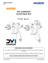
Standard Flow Meter 310-9000
Acid Catalyst Flow Meter 310-9002
for RM2 and RF2
Scan the related QR code above for other languages
of this ow meter service manual and additional
product information.
RF2 RM2


77-3154-R1 (05/2023)3/34www.carlisleft.com
EN CONTENTS
CONTENTS
SAFETY 4-8
Safety Precautions ............................................................................................................................................ 4
Hazards/Safeguards ........................................................................................................................................ 5-8
INTRODUCTION 9-10
Standard Flow Meter 310-9000 Introduction ........................................................................................................ 9
Acid Catalyst Flow Meter 310-9002 Introduction ................................................................................................ 10
INSTALLATION 11-12
Flow Meter General Information ........................................................................................................................ 11
Intrinsically Safe Operation ............................................................................................................................... 12
OPERATION 13
Principle of Operation ..................................................................................................................................... 13
Calibration ...................................................................................................................................................... 13
Flow Meter Automatic Clean Procedure ............................................................................................................. 13
MAINTENANCE 14-31
Flow Meter Servicing Overview ......................................................................................................................... 14
Disassembly, Inspection, and Assembly ............................................................................................................. 15
Standard Flow Meter Components..................................................................................................................... 24
Acid Catalyst Flow Meter Components ............................................................................................................... 26
Dual Pickup Sensor Cables ............................................................................................................................... 28
Fiber Optic Pickup Sensor Cables ...................................................................................................................... 30
MANUAL REVISIONS 32
Manual Revisions Summary .............................................................................................................................. 32
WARRANTY 34
Warranty ......................................................................................................................................................... 34

EN
77-3154-R1 (05/2023) 4/34 www.carlisleft.com
SAFETY
The hazards shown on the following pages may
occur during the normal use of this equipment.
WARNING!: Indicates a hazardous situation that, if
not avoided, could result in death or serious injury.
Caution!: Indicates a hazardous situation that, if
not avoided, could result in minor or moderate
injury or equipment damage.
Notice: Indicates information considered important
but not hazard related.
SAFETY PRECAUTIONS
Before operating, maintaining or servicing any
electrostatic coating system, read and understand
all of the technical and safety literature for your
products. This manual contains information that
is important for you to know and understand.
This information relates to USER SAFETY and
PREVENTING EQUIPMENT PROBLEMS.
To help you recognize this information, we use the
following symbols. Please pay particular attention to
these sections.
While this manual lists standard specications and
service procedures, some minor deviations may be
found between this literature and your equipment.
Dierences in local codes and plant requirements,
material delivery requirements, etc., make such
variations inevitable. Compare this manual with
your system installation drawings and associated
equipment manuals to reconcile such dierences.
Careful study and continued use of this manual will
provide a better understanding of the equipment
and process, resulting in more ecient operation,
longer trouble-free service and faster, easier
troubleshooting. If you do not have the manuals
and safety literature for your equipment, contact
your local Carlisle Fluid Technologies representative
or Carlisle Fluid Technologies technical support.
SAFETY
Repairs may only be performed by personnel
authorized by Carlisle Fluid Technologies.
The user MUST read and be familiar with the
Safety Section in this manual and the safety
literature therein identied.
This equipment is intended to be used by trained
personnel ONLY.
This manual MUST be read and thoroughly
understood by ALL personnel who operate, clean
or maintain this equipment! Special care should be
taken to ensure that the WARNINGS and safety
requirements for operating and servicing the
equipment are followed.
The user should be aware of and adhere to ALL
local building and re codes and ordinances as
well as NFPA 33 AND EN 16985 SAFETY
STANDARDS, LATEST EDITION, or applicable
country safety standards, prior to installing,
operating, and/or servicing this equipment.

77-3154-R1 (05/2023)5/34www.carlisleft.com
EN SAFETY
AREA
Tells where hazards
may occur
HAZARDS
Tells what the hazard is
SAFEGUARDS
Tells how to avoid the hazard
Spray Area Fire Hazard
Improper or inadequate
operation and maintenance
procedures will cause a re
hazard.
Protection against
inadvertent arcing that
is capable of causing
re or explosion is lost if
any safety interlocks are
disabled during operation.
Frequent Power Supply
or Controller shutdown
indicates a problem in the
system requiring correction.
Fire extinguishing equipment must be present in
the spray area and tested periodically.
Spray areas must be kept clean to prevent the
accumulation of combustible residues.
Smoking must never be allowed in the spray area.
The high voltage supplied to the atomizer must
be turned o prior to cleaning, ushing, or
maintenance.
Spray booth ventilation must be kept at the rates
required by NFPA 33, EN 16985, country, and
local codes. In addition, ventilation must be
maintained during cleaning operations using
ammable or combustible solvents.
Electrostatic arcing must be prevented. Safe
sparking distance must be maintained between the
parts being coated and the applicator. A distance of
1 inch (25mm) for every 10KV of output voltage is
required at all times.
Test only in areas free of combustible material.
Testing may require high voltage to be on, but only
as instructed.
Non-factory replacement parts or unauthorized
equipment modications may cause re or injury.
If used, the key switch bypass is intended for use
only during setup operations. Production should
never be done with safety interlocks disabled.
The paint process and equipment should be set up
and operated in accordance with NFPA 33, NEC,
OSHA, local, country, and European Health and
Safety Norms.

EN
77-3154-R1 (05/2023) 6/34 www.carlisleft.com
SAFETY
AREA
Tells where the
hazard may occur
HAZARD
Tells what the hazard is
SAFEGUARDS
Tells how to avoid the hazard
Spray Area Explosion Hazard
Improper or inadequate
operation and maintenance
procedures will cause a re
hazard.
Protection against
inadvertent arcing that
is capable of causing
re or explosion is lost if
any safety interlocks are
disabled during operation.
Frequent Power Supply
or Controller shutdown
indicates a problem in the
system requiring correction.
Electrostatic arcing must be prevented. Safe
sparking distance must be maintained between the
parts being coated and the applicator. A distance of
1 inch (25mm) for every 10KV of output voltage is
required at all times.
Unless specically approved for use in hazardous
locations, all electrical equipment must be located
outside or applicable county code hazardous areas,
in accordance with NFPA 33.
Test only in areas free of ammable or combustible
materials.
The current overload sensitivity (if equipped) MUST
be set as described in the related section of the
equipment manual. Protection against inadvertent
arcing that is capable of causing re or explosion
is lost if the current overload sensitivity is not
properly set. Frequent power supply shutdown
indicates a problem in the system which requires
correction.
Always turn the control panel power o prior to
ushing, cleaning, or working on spray system
equipment.
Before turning high voltage on, make sure no
objects are within the safe sparking distance.
Ensure that the control panel is interlocked with the
ventilation system and conveyor in accordance with
NFPA-33, EN 16985.
Have re extinguishing equipment readily available
and tested periodically.
General Use and
Maintenance Improper operation or
maintenance may create a
hazard.
Personnel must be properly
trained in the use of this
equipment.
Personnel must be given training in accordance with
the requirements of NFPA 33.
Instructions and safety precautions must be read
and understood prior to using this equipment.
Comply with appropriate local, state, and national
codes governing ventilation, re protection,
operation maintenance, and housekeeping.
Reference OSHA, NFPA 33, EN Norms and your
insurance company requirements.v

77-3154-R1 (05/2023)7/34www.carlisleft.com
EN SAFETY
AREA
Tells where the
hazard may occur
HAZARD
Tells what the hazard is
SAFEGUARDS
Tells how to avoid the hazard
Spray Area /
High Voltage
Equipment
Electrical Discharge
There is a high voltage
device that can induce
an electrical charge on
ungrounded objects which
is capable of igniting
coating materials.
Inadequate grounding
will cause a spark hazard.
A spark can ignite many
coating materials and cause
a re or explosion.
Parts being sprayed and operators in the spray area
must be properly grounded.
Parts being sprayed must be supported on
conveyors or hangers that are properly grounded.
The resistance between the part and earth ground
must not exceed 1 Meg Ohm. (Refer to NFPA 33,
EN 16985.)
Operators must be grounded. Grounding straps
on wrists or legs may be used to assure adequate
ground contact.
Footware to be used by operator shall comply with
EN ISO 20344, resistance not to exceed 100 Meg
Ohm. Protective clothing including gloves should
comply with EN 1149-5, resistance not to exceed
100 Meg Ohm.
Operators must not be wearing or carrying any
ungrounded metal objects.
When using an electrostatic handgun, operators
must assure contact with the handle of the
applicator via conductive gloves or gloves with the
palm section cut out.
NOTE: REFER TO NFPA 33, EN 16985 OR SPECIFIC
COUNTRY SAFETY CODES REGARDING PROPER
OPERATOR GROUNDING.
All electrically conductive objects in the spray area,
with the exception of those objects required by the
process to be at high voltage, must be grounded.
Grounded conductive ooring must be provided in
the spray area.
Always turn o the power supply prior to ushing,
cleaning, or working on spray system equipment or
applicable county code.
Unless specically approved for use in hazardous
locations, all electrical equipment must be located
outside or applicable country code, hazardous
areas, in accordance with NFPA 33.
Avoid installing an applicator into a uid system
where the solvent supply is ungrounded.
Do not touch the applicator electrode while it is
energized.

EN
77-3154-R1 (05/2023) 8/34 www.carlisleft.com
SAFETY
AREA
Tells where the
hazard may occur
HAZARD
Tells what the hazard is
SAFEGUARDS
Tells how to avoid the hazard
Electrical
Equipment Electrical Discharge
High voltage equipment
is utilized in the process.
Arcing in the vicinity of
ammable or combustible
materials may occur.
Personnel are exposed
to high voltage during
operation and maintenance.
Protection against
inadvertent arcing that may
cause a re or explosion
is lost if safety circuits are
disabled during operation.
Frequent power supply
shut-down indicates a
problem in the system
which requires correction.
An electrical arc can ignite
coating materials and cause
a re or explosion.
Unless specically approved for use in hazardous
locations, the power supply, control cabinet, and all
other electrical equipment must be located outside
or applicable country codes, hazardous areas in
accordance with NFPA 33 and EN 16985.
Turn the power supply OFF before working on
the equipment.
Test only in areas free of ammable or combustible
material.
Testing may require high voltage to be on, but only
as instructed.
Production should never be done with the safety
circuits disabled.
Before turning the high voltage on, make sure no
objects are within the sparking distance.
Toxic Substances Chemical Hazard
Certain materials may be
harmful if inhaled, or if
there is contact with the
skin.
Follow the requirements of the Safety Data Sheet
supplied by coating material manufacturer.
Adequate exhaust must be provided to keep the air
free of accumulations of toxic materials. Reference
EN 12215 or applicable code.
Use a mask or respirator whenever there is a
chance of inhaling sprayed materials. The mask
must be compatible with the material being
sprayed and its concentration. Equipment must be
as prescribed by an industrial hygienist or safety
expert, and be NIOSH approved.
Spray Area Explosion Hazard -
Incompatible Materials
Halogenated hydrocarbon
solvents for example:
Methylene chloride and
1,1,1, - Trichloroethane are
not chemically compatible
with the aluminum that
might be used in many
system components. The
chemical reaction caused
by these solvents reacting
with aluminum can become
violent and lead to an
equipment explosion.
Spray applicators require that aluminum inlet
ttings be replaced with stainless steel.
Aluminum is widely used in other spray application
equipment - such as material pumps, regulators,
triggering valves, etc. Halogenated hydrocarbon
solvents must never be used with aluminum
equipment during spraying, ushing, or cleaning.
Read the label or data sheet for the material you
intend to spray. If in doubt as to whether or not a
coating or cleaning material is compatible, contact
your coating supplier. Any other type of solvent may
be used with aluminum equipment.

77-3154-R1 (05/2023)9/34www.carlisleft.com
EN INTRODUCTION
INTRODUCTION
310-9000 DESCRIPTION
The Ransburg 310-9000 ow meter is developed to precisely meter and monitor uid ows. This ow meter,
in many cases, surpasses the performance of other types of meters currently used.
FLOW RATE ACCURACY
A ow rate accuracy of 0.5% is typical with many uids if the ow meter is calibrated at or near the
expected ow rates. Even with wide ow rate swings (such as when used with robots under analog control),
an accuracy of ± 2% is possible.
REVERSE FLOW DETECTION
The sensors (pickups) are available in single or dual-sensor versions. The dual sensor version outputs two
square waves in quadrature mode so that sensing circuitry can determine ow rate and direction. If it is
necessary to sense the reverse ow of the material, the dual-sensor version should be used.
FLUID PASSAGES
The ow meter requires 3/8” AN male ttings. This tting style eliminates ow “dead space” and removes
the need for specially designed ttings or TFE inserts. When a streamlined uid passage is made, the color
change time of the meter is improved.
SPECIFICATIONS
310-9000 Ransburg Flow Meter Operation Specications
Flow Rate: 10–3,000 cc/min (material dependent)
Accuracy: ± 0.5%
Max Working Pressure: 6,000 psi (413.69 bar/41369 kPa) @ 100 °F (37.77 °C)
Temperature: -40–140 °F (-40 °C to 60 °C)
Signal Output: 2 Channel Quadrature, 56,000 pulses per liter
Power: 10–30 VDC
310-9000 Ransburg Flow Meter Materials Specications
Body: 303 Stainless Steel / DIN 1.4305
Gears: DIN 1.4122
Sleeve Bearings: Tungsten Carbide
Shafts: Tungsten Carbide
Seal: PTFE
Filtration Required: 120 Microns
Connections: 9/16-18G (JIC 37) ports
Weight: 3.6 lbs (1.6 Kg)

EN
77-3154-R1 (05/2023) 10/34 www.carlisleft.com
INTRODUCTION
310-9002 DESCRIPTION
The Ransburg 310-9002 acid catalyst ow meter is developed to precisely meter and monitor uid ows.
This ow meter, in many cases, surpasses the performance of other types of meters currently used.
FLOW RATE ACCURACY
A ow rate accuracy of 0.5% is typical with many uids if the ow meter is calibrated at or near the
expected ow rates. Even with wide ow rate swings (such as when used with robots under analog control),
an accuracy of ± 2% is possible.
REVERSE FLOW DETECTION
The sensor (pickups) is a dual-probe version. The dual sensor version outputs two square waves in
quadrature mode so that sensing circuitry can determine ow rate and direction. If it is necessary to sense
the reverse ow of the material, the dual-sensor version should be used.
FLUID PASSAGES
The ow meter requires 3/8” AN male ttings. This tting style eliminates ow “dead space” and removes
the need for specially designed ttings or TFE inserts. When a streamlined uid passage is made, the color
change time of the meter is improved.
SPECIFICATIONS
310-9002 Ransburg Flow Meter Operation Specications
Flow Rate: 4–1893 cc/min (material dependent)
Accuracy: ± 0.5%
Max Working Pressure: 6,000 psi (413.69 bar/41369 kPa) @ 100 °F (37.77 °C)
Temperature: -40–140 °F (-40 °C to 60 °C)
Signal Output: 2 Channel Quadrature, 56,000 pulses per liter
Power: 10–30 VDC
310-9002 Ransburg Flow Meter Materials Specications
Body: 316 Stainless Steel / DIN 1.4404
Gears: DIN 1.4122
Sleeve Bearings: Tungsten Carbide
Shafts: Tungsten Carbide
Seal: PTFE
Filtration Required: 120 Microns
Connections: 9/16-18G (JIC 37) ports
Weight: 3.6 lbs (1.6 Kg)

77-3154-R1 (05/2023)11/34www.carlisleft.com
EN INSTALLATION
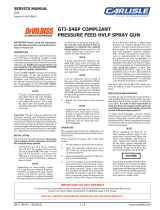
GENERAL INFORMATION
The unit can be mounted with the bolt pattern shown below. Mount the ow meter vertically so the gear
faces are perpendicular to the earth’s horizon. This mount position minimizes the eect of gravity on the
gears. The ow direction must be plumbed as marked on the side label of the meter. The uid inlet is
opposite the sensor connection. Two (2) 1/4-20 screws must be used.
ELECTRICAL NOISE
Although not required, the meter can be plumbed so the ow enters at the bottom of the meter and exits at
the top. This type of plumbing eliminates the possibility of air entrapment in the meter.
Make sure that the ow meter cables are not put closer than 12” to noise generation devices. For example,
large electric motors, uorescent lighting, transformers, ballasts, etc.
INSTALLATION
This ow meter can be installed in Class I, Division I, and Group D locations when used with the correct
Zener Barrier. Refer to pages 14-17 for more details.
OUTLET PORT
Ø 3.30” (Ø 84 mm)
INLET PORT
1.730”
(196.35 mm)
M6 x 20 mm THD
x 12 mm DEEP
(2 PLACES)

EN
77-3154-R1 (05/2023) 12/34 www.carlisleft.com
The ow meter can be operated in hazardous areas (Class I, Division I, Group D locations). It is necessary to
route the power to the ow meter and the signal (or signals) that return from the ow meter sensor through
an approved Zener barrier.
The ow meter with the dual-probe pickup sensor (PN 310-9011) is included with the Remote Fluid Panel
Kit, Barrier & F.O. Transceiver Box kits 310-8020 and 310-8021. For installation information, see Installation
Manual 77-3155.
The ow meter with the ber optic pickup sensor (PN 310-9012) is included with the In-Booth Remote Fluid
Panel kits 310-8022 and 310-8023. For installation information, see Installation Manual 77-3155.
OPERATION-INTRINSICALLY SAFE
INTRINSICALLY SAFE OPERATION

77-3154-R1 (05/2023)13/34www.carlisleft.com
EN
OPERATION
PRINCIPLE OF OPERATION
Gear-type ow meters work on the principle that a small material is trapped between each gear’s teeth.
One to two proximity sensors detect each gear tooth rotation as the gears rotate. When a gear tooth passes
a proximity sensor, the sensor sends a square wave pulse back to the controller to indicate one of those
material cavities has passed through the meter.
Flow Meters are typically calibrated by the pulse count occurrences when one liter of material has passed
through the meter. That value is generally called the calibration value or calibration factor and is expressed
in pulses per liter (ppl). Although this value would stay the same from material to material, it is dierent
because it varies based on several factors. These factors include (but are not necessarily limited to) viscosity,
ow rate, material temperature, percent of solids, the lubricity of the material, solvent vs. water-based, and
whether or not the material is thixotropic. As a result, gear-type ow meters must be calibrated with the
material used during production and at the expected ow rates.
CALIBRATION
The ow meter must be calibrated periodically as the calibration value (in pulses per liter or PPL) will vary
based on viscosity, ow rate, temperature, wear, and other factors. Refer to the appropriate associated
equipment documentation for the proper calibration procedure.
PROCEDURE TO AUTOMATICALLY CLEAN THE FLOW METER
Fluid Line Air Purges
Air purges are used in automatic coating operations for rapid color changes and to minimize the solvent
required to ush out the old color. Special considerations must be made when air purges through the ow
meter are used.
1. Long air purges do not provide the lubrication the ow meter gears require. The metered uid or
solvent typically delivers this lubrication.
2. Air purges can cause coating materials to thicken or dry on the ow meter shafts and gears. Such
materials will aect the performance characteristics of the ow meter, primarily when water-based
materials are used.
3. Long air purges will cause premature gear and shaft failure.
4. All clean cycles must start with a solvent push to prevent dried coating materials on ow meter parts.
5. Solvent and air “chop” cycles are recommended as the most satisfactory method to ush ow meters.
6. On plural-component materials or other materials that cause a ’skinning’ eect on the inside of the uid
lines, it is recommended that they be lled with non-pressurized solvent during idle times. The system
must be ushed before the next spray cycle load.
7. Air purges are not recommended for water-based applications.
OPERATION

EN
77-3154-R1 (05/2023) 14/34 www.carlisleft.com
FLOW METER SERVICING OVERVIEW
Flow Meter problems can be caused by incorrectly ltered uid.
Particulates in the uid can cause the gears
to bind, and the results are incorrect signals for the actual ow rate. Refer to the instructions from the lter
manufacturer to maintain the uid lters. If the disassembly and clean procedures are needed again and
again to remove solids and particulates, examine the full uid supply system and make an analysis of the
system’s automatic clean procedure cycle.
Fluid backup (reverse ow) can cause reacted or catalyzed material to enter the ow meter. The 2K controls
will sense the reverse ow, and the system will shut down. Immediately clean the ow meter before the
uid sets up. During regular operation, the magnetic sensors or electrical connections will not need to be
replaced.
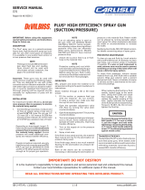
BOTTOM BODY (EXTERNAL) TORQUE SEQUENCE (EXTERNAL)
BOTTOM BODY (INTERNAL) TOP BODY (INTERNAL)
2 7
9 5
8 1
6 10
4 3
3.30”
(84 mm)
1.730”
(196.35 mm)
5 mm Socket
Head Cap Screw
Fluid Outlet
Fluid InletAlignment
Pins (two)
FLUID FLOW
DIRECTION
M6 x 20 mm THD
x 12 mm DEEP
(2 PLACES)
MAINTENANCE

77-3154-R1 (05/2023)15/34www.carlisleft.com
EN MAINTENANCE
DISASSEMBLY
These instructions are only applicable after the
upper and lower material lines are disconnected,
and the ow meter assembly with attached bracket
is removed from the uid panel for servicing.
Dual Probe Pickup Sensor Removal
1. Disconnect the ow meter cable (a) from the
dual probe pickup sensor (b).
2.
Loosen the two hex head cap screws (c) marked
in red. These are captive screws and will remain
with the pickup sensor when removed from the
ow meter body.
DISASSEMBLY, INSPECTION, AND ASSEMBLY
a
b
c

EN
77-3154-R1 (05/2023) 16/34 www.carlisleft.com
3. Carefully
pull the pickup sensor (b) straight
out and away from the ow meter body.
Move the pickup sensor to a clean, safe area to
prevent damage. Do not drop the pickup.
The dual probe pickup sensor is a sensitive device.
If dropped, damage can occur and cause unstable
or incorrect ow indications.
Go to page 18 to continue the ow meter
disassembly procedure.
b
MAINTENANCE

77-3154-R1 (05/2023)17/34www.carlisleft.com
EN MAINTENANCE
Fiber Optic Pickup Sensor Removal
1. Disconnect the ow meter ber optic cable
(d) from the ber optic pickup sensor (e).
2. Loosen the jam nut (f) on the pickup sensor
where it touches the ow meter’s front face.
3. Turn the pickup sensor (e) counterclockwise to
remove it from the ow meter body. Move the
pickup sensor to a clean, safe area to prevent
damage. Do not drop the pickup.
The ber optic pickup sensor is a sensitive device.
If dropped, damage can occur and cause unstable
or incorrect ow indications.
Go to page 18 to continue the ow meter
disassembly procedure.
d
f
e
e

EN
77-3154-R1 (05/2023) 18/34 www.carlisleft.com
MAINTENANCE
4. Remove two each of the hex head cap screws
(g), external tooth lock washers (h), and at
washers (i) from the back of the bottom ow
meter body.
Put the mounting bracket (j) and all fastener
hardware in a safe area.
5. Remove the upper and lower hose adapters (k)
from the bottom ow meter body (m).
6. Clean the remaining thread tape or sealant from
the adapters and threaded holes (l) in the bottom
body.
7. If the decals are missing, put a mark across the
halves before separation to later identify their
related positions for reassembly.
8. Use a 5mm hex key wrench and remove the ten
(n) socket head cap screws.
g
h
i
j
kl
m
k
n
The ow meter body halves are labeled with decals
on the same side to help with reassembly.
The ow meter servicing procedures are identical
for the standard and acid catalyst ow meters.

77-3154-R1 (05/2023)19/34www.carlisleft.com
EN MAINTENANCE
9.
Divide the top (o) and bottom (m) ow meter
body halves. Put the ow meter body halves in a
clean work area with the mating surfaces pointed
up. Do not let these surfaces get damaged,
especially where the o-ring gasket is set.
If separation of the halves is not easy, do not pry
apart the body halves with a screwdriver or other
such tool. Damage to the mating surfaces, gear
shafts, or shaft bearings can occur.
An alternative method of separation is to:
a) Put two socket head cap screws (n) through
opposite sides of the ow meter and give the
screws a few turns each.
b) Tightly hold the top body, then tap the screw
heads with a soft mallet until separation is
complete.
10. Remove and discard the o-ring gasket (p).
11. Remove the gears (q) and shafts (r) from the
shaft bores in the measuring chamber.
m
o
p
q
r
Discard the used o-ring gasket. O-ring gaskets
cannot be reused, but must always be replaced
with new ones during ow meter body servicing.

EN
77-3154-R1 (05/2023) 20/34 www.carlisleft.com
MAINTENANCE
INSPECTION
Use an applicable solvent and clean the remaining
material from all ow meter parts.
Examine all following parts for wear and damage:
1. The gear shafts (r) must measure the same
diameter at the ends and center. Replace the
gear shaft set if a shaft does not measure the
same at the three locations or if there are scores,
scratches, or damage to the shaft.
2. The gear teeth (q) must not be worn, chipped,
pitted, broken, or missing. Replace the gear set if
there is damage to a gear.
3. The gear shaft bearing(s) must not be worn,
pitted, or have scores or scratches. Replace the
gear set if a bearing has damage or the gears
wobble on the shafts.
4. The shaft bearings (u) in the top ow meter body
(o) must not be worn, pitted, or have scores or
scratches.
Put the gear shafts into the top body bearings
and try to wobble them. Replace the top body if a
bearing has damage or the gear shafts wobble in
the bearings.
5. The ow meter top’s mating face (t) must not be
gouged, scored, scratched, or pitted. Replace the
top body if there is damage.
r
q
t u
s
o
MUST BE THE SAME DIAMETER
/