Page is loading ...

PL e
3
PGV100A-F200*-B28-V1D /
PGV100AQ-F200*-B28-V1D
(safePGV)
Data Matrix Positioning
System for Automated
Guided Vehicles (AGV)
Instruction

With regard to the supply of products, the current issue of the following document is applicable: The
General Terms of Delivery for Products and Services of the Electrical Industry, published by the Central
Association of the Electrical Industry (Zentralverband Elektrotechnik und Elektroindustrie (ZVEI) e.V.)
in its most recent version as well as the supplementary clause: "Expanded reservation of proprietor-
ship"
Worldwide
Pepperl+Fuchs Group
Lilienthalstr. 200
68307 Mannheim
Germany
Phone: +49 621 776 - 0
E-mail: info@de.pepperl-fuchs.com
North American Headquarters
Pepperl+Fuchs Inc.
1600 Enterprise Parkway
Twinsburg, Ohio 44087
USA
Phone: +1 330 425-3555
E-mail: sa[email protected]hs.com
Asia Headquarters
Pepperl+Fuchs Pte. Ltd.
P+F Building
18 Ayer Rajah Crescent
Singapore 139942
Phone: +65 6779-9091
E-mail: sa[email protected]rl-fuchs.com
https://www.pepperl-fuchs.com

3
PGV100A-F200*-B28-V1D / PGV100AQ-F200*-B28-V1D (safePGV)
Contents
2020-10
1 Introduction................................................................................................................ 5
1.1 Content of this Document............................................................................. 5
1.2 About This Documentation ........................................................................... 5
1.3 Symbols Used ................................................................................................ 6
2 Safety Information ..................................................................................................... 7
3 Product Description .................................................................................................. 8
3.1 Components of the Positioning System...................................................... 8
3.2 Intended Use .................................................................................................. 8
3.3 Improper Use.................................................................................................. 8
3.4 Safety Concept............................................................................................... 9
3.5 Dimensions of the Components of the Positioning System.................... 10
3.6 LED Indicators and Operating Elements................................................... 12
3.7 Accessories.................................................................................................. 13
3.8 Marking ......................................................................................................... 13
3.9 Technical Specifications ............................................................................. 14
3.9.1 Reader.............................................................................................................................. 14
3.9.2 Data Matrix Code Tape ..................................................................................................... 16
3.10 Standards and Directives for Functional Safe .......................................... 17
4 Transport and Storage ............................................................................................ 18
5 Planning.................................................................................................................... 19
5.1 Plant Design ................................................................................................. 19
5.2 System Behavior.......................................................................................... 19
5.3 Assumptions ................................................................................................ 20
5.4 Safety Function and Safe State .................................................................. 20
5.5 Characteristic Safety Values....................................................................... 22
5.6 Safety-related reading range of the read head......................................... 23
5.7 Useful Lifetime ............................................................................................. 25
6 Installation................................................................................................................ 26
6.1 General ......................................................................................................... 26
6.2 Safe Position Detection – Structural Principle.......................................... 26
6.3 Mounting of the Reader............................................................................... 27
6.4 Aligning the Reader..................................................................................... 31

PGV100A-F200*-B28-V1D / PGV100AQ-F200*-B28-V1D (safePGV)
Contents
4
2020-10
6.5 Affixing the Data Matrix Code Tape............................................................31
6.5.1 Expansion Joints/Gaps ..................................................................................................... 32
6.5.2 Hysteresis Y Axis .............................................................................................................. 33
6.5.3 Reader Orientation and Value Outputs.............................................................................. 34
6.5.4 Bends ............................................................................................................................... 36
6.5.5 Branches/Lane Change ................................................................................................... 37
6.5.6 Intersections .................................................................................................................... 40
6.5.7 Position Jump ................................................................................................................... 42
6.6 Electrical Connection ..................................................................................43
6.7 PROFINET Connection ................................................................................45
7 Commissioning ........................................................................................................46
8 Operation and Communication ..............................................................................48
8.1 Communication via PROFINET...................................................................48
8.1.1 General Information on Communication via PROFINET ................................................... 48
8.1.2 PROFINET I/O Interface ................................................................................................... 49
8.1.2.1 Identification & Maintenance (I&M) Data ............................................................................... 49
8.1.3 Project Planning Using Device Description ....................................................................... 50
8.1.4 PROFINET Modules ......................................................................................................... 51
8.1.4.1 Modules with Input Data Telegram......................................................................................... 51
8.2 PROFINET Diagnostic Information.............................................................58
8.3 Communication via PROFIsafe...................................................................60
8.3.1 General Information on the PROFIsafe Layer.................................................................... 60
8.3.2 PROFIsafe Protocol Structure........................................................................................... 60
8.3.3 PROFIsafe-Specific Parameters ....................................................................................... 61
8.3.4 PROFIsafe Address and Identification of the Device......................................................... 61
8.3.5 PROFIsafe Module ........................................................................................................... 62
9 Maintenance .............................................................................................................65
9.1 Maintenance .................................................................................................66
9.2 Testing...........................................................................................................66
9.3 Cleaning........................................................................................................66
9.4 Repairs ..........................................................................................................66
10 Disposal ....................................................................................................................67
11 Change History ........................................................................................................68

PGV100A-F200*-B28-V1D / PGV100AQ-F200*-B28-V1D (safePGV)
Introduction
2020-10
5
1 Introduction
1.1 Content of this Document
This document contains safety-relevant information for using the device. This information is
required to use the product in the relevant phases of the product life cycle. This may include
information on the following:
•Product identification
•Delivery, transport, and storage
•Mounting and installation
•Commissioning and operation
•Maintenance and repair
•Troubleshooting
•Dismounting
•Disposal
The documentation comprises the following parts:
•Original instructions (this document)
•Instruction manual
•EU declaration of conformity
•Datasheet
For more information about Pepperl+Fuchs products with functional safety, see www.pepperl-
fuchs.com/sil.
1.2 About This Documentation
Note on Figures in the Documentation
The figures in this documentation are provided for basic understanding and may deviate from
the actual design.
Note
Availability of the Complete Product Documentation
Full information about the product can be found in the product documentation online at
www.pepperl-fuchs.com. This documentation can be accessed by entering the product name
(type code) or the item number of the product into the search field on the website.

2020-10
6
PGV100A-F200*-B28-V1D / PGV100AQ-F200*-B28-V1D (safePGV)
Introduction
1.3 Symbols Used
This document contains symbols for the identification of warning messages and of informative
messages.
Warning Messages
You will find warning messages, whenever dangers may arise from your actions. It is mandatory
that you observe these warning messages for your personal safety and in order to avoid prop-
erty damage.
Depending on the risk level, the warning messages are displayed in descending order as fol-
lows:
Informative Symbols
Action
This symbol indicates a paragraph with instructions. You are prompted to perform an action or
a sequence of actions.
Danger!
This symbol indicates an imminent danger.
Non-observance will result in personal injury or death.
Warning!
This symbol indicates a possible fault or danger.
Non-observance may cause personal injury or serious property damage.
Caution!
This symbol indicates a possible fault.
Non-observance could interrupt the device and any connected systems and plants, or result in
their complete failure.
Note
This symbol brings important information to your attention.

PGV100A-F200*-B28-V1D / PGV100AQ-F200*-B28-V1D (safePGV)
Safety Information
2020-10
7
2 Safety Information
Read the information in this document carefully and observe this information when working
with the device. Failure to observe the safety information and warning messages in this docu-
mentation can lead to malfunctions of the safety devices of the machines or plants in which
they are fitted.
This can result in serious personal injury or death.
Target Group, Personnel
Responsibility for planning, assembly, commissioning, operation, maintenance, and dismount-
ing lies with the plant operator.
The personnel must be appropriately trained and qualified in order to carry out mounting,
installation, commissioning, operation, maintenance, and dismounting of the device. The
trained and qualified personnel must have read and understood the instruction manual.
Prior to using the product make yourself familiar with it. Read the instruction manual carefully.
Reference to Further Documentation
Observe laws, standards, and directives applicable to the intended use and the operating loca-
tion.

2020-10
8
PGV100A-F200*-B28-V1D / PGV100AQ-F200*-B28-V1D (safePGV)
Product Description
3 Product Description
3.1 Components of the Positioning System
The positioning system described in these original instructions consists of the following compo-
nents:
•Reader PGV100A-F200*-B28-V1D / PGV100AQ-F200*-B28-V1D (safePGV), hereinafter
referred to as "reader."
•2-colored Data Matrix code tapes PXV*-AA25-* and PXV*-AAM*-*, specially developed
for this safety application, hereinafter referred to as "Data Matrix code tape."
3.2 Intended Use
This reader, which works with a special stationary two-colored Data Matrix code tape affixed to
the ground, is a high resolution positioning system. It can be used in all applications where
automated guided vehicles (AGV) are to be positioned precisely at marked positions along a
given track.
The reader forms part of the positioning system in the Pepperl+Fuchs incident light process.
The device's features include a camera module with an internal illumination unit, which follows
a parallel stationary Data Matrix code tape affixed to the ground to detect a safe position
according to SIL 3/PL e. The reader is located on an automated guided vehicle (AGV), for
which it outputs the position data.
The positioning system outputs safe values, which achieve a degree of reliability as required by
SIL 3 and PL e. The prerequisite for this is that the positioning device is integrated into the plant
and operated within the safe parameters, as described in these original instructions.
Ensure that this device is only used in accordance with the technical specification described in
these instructions with the approved Data Matrix code tape.
The device is only approved for appropriate and intended use. Ignoring these instructions will
void any warranty and absolve the manufacturer from any liability.
3.3 Improper Use
Protection of the personnel and the plant is not ensured if the device is not used according to its
intended use.
The device must not be used in an explosion-hazardous area.

PGV100A-F200*-B28-V1D / PGV100AQ-F200*-B28-V1D (safePGV)
Product Description
2020-10
9
3.4 Safety Concept
The reader forms part of the positioning system in the Pepperl+Fuchs incident light process.
The device's features include a camera module with an internal illumination unit, which follows
a parallel stationary Data Matrix code tape affixed to the ground to detect a safe position
according to SIL 3/PL e. The reader is connected to PROFIsafe and is located on an automated
guided vehicle (AGV), for which it outputs position data.
To achieve SIL 3/PL e, a single reader connected to PROFIsafe with the appropriate Data
Matrix code tape is required.
To achieve SIL 3/PL e, a single reader connected to PROFIsafe with the appropriate 2-colored
Data Matrix code tape is required.
Reader Functionality
The reader offers reliable operation thanks to the 2-colored red/blue lighting of the camera
module. In an algorithm evaluated as safe, the 2-color, red/blue Data Matrix code tape is also
illuminated and the function of the camera module is continuously monitored.
If the red LED ring of the reader is active, the blue and black areas are visible in the Data Matrix
code. If the blue LED ring of the reader is active, the red and black areas are visible in the Data
Matrix code.
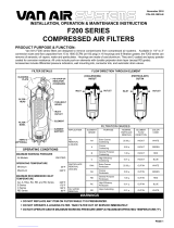
Figure 3.1 Functional principle: Data Matrix code tape for safe positioning
Note
Note the Type of Code Tape!
The positioning system only works if the reader is used together with one of the 2-colored Data
Matrix code tapes of the following type: PXV*-AA25-* or PXV*-AAM*-*.
The use of other code tapes is not permitted!
Note
Reader Behavior Without PROFIsafe
If the reader is operated without PROFIsafe communication, it flashes red only and does not
output safe X position data.
12-colored Data Matrix code tape
2Data Matrix code with red lighting
3Data Matrix code with blue lighting
4Monochrome Data Matrix codes
PXV-AA25
000 000.0 m www.pepperl-fuchs.com 1
2
3
4

2020-10
10
PGV100A-F200*-B28-V1D / PGV100AQ-F200*-B28-V1D (safePGV)
Product Description
The use of the two colors by the camera module and Data Matrix code tape and the inspection
by a built-in intelligent algorithm guarantee the redundant 2-channel detection of the X position
data, thus ensuring reliable operation according to SIL 3/PL e.
During positioning, the reader uses all non-safe position data. In addition to the non-safe X
position, this includes the Y and Z position, angle, speed, error bit, and warning bit.
During positioning, the reader checks whether the reliably determined 2-channel X position
data for navigation is within the tolerance range, i.e., within the dimensions of the safety-related
reading range of the X safety data.
3.5 Dimensions of the Components of the Positioning System
Figure 3.2 Dimensions of PGV100A-F200A-B28-V1D
Dimensions of the Reader
10 70 12
94.5
70
50
22
ø 25
M6 x 9 (4x)
12.5 20 20

PGV100A-F200*-B28-V1D / PGV100AQ-F200*-B28-V1D (safePGV)
Product Description
2020-10
11
Figure 3.3 Dimensions of PGV100A-F200-B28-V1D
Figure 3.4 Dimensions of the Data Matrix code tape
Dimensions of the Reader
Dimensions of the Data Matrix Code Tape
10
70 12
84.5
70
50
22
ø 25
M6 x 9 (4x)
12.5 20 20
80
12.5
PXV-AA25
000 000.0 m www.pepperl-fuchs.com
7 15
25
520
3
15

2020-10
12
PGV100A-F200*-B28-V1D / PGV100AQ-F200*-B28-V1D (safePGV)
Product Description
3.6 LED Indicators and Operating Elements
The reader has 7 indicator LEDs for carrying out visual function checks and quick diagnosis.
LEDs 5 and 6 have no function.
The reader has the following 2 buttons on the back of the device:
•Key 1: SERVICE: used for internal service purposes.
•Key 2: NO FUNCTION: without function.
Figure 3.5 Displays and Operating Elements
Description of the LED Indicators
LED no. Status Description
1 Lights up green PROFINET connection activated
2 Flashes yellow PROFINET TX/RX data transfer
3 Lights up red PROFINET communication error
4 Lights up red System error
Lights up green Normal operation, Data Matrix code tape detected
Flashes red Data Matrix code not recognized
7 Lights up red Internal error
-> return delivery to Pepperl+Fuchs
Table 3.1 State and description of the LED indicators
SERVICE
NO FUNCTION
1
2
LED 1 2 3 4 5 6 7

PGV100A-F200*-B28-V1D / PGV100AQ-F200*-B28-V1D (safePGV)
Product Description
2020-10
13
3.7 Accessories
Compatible accessories offer potential for cost savings when commissioning, replacing, and
servicing our products.
If products are used in harsh ambient conditions, appropriate Pepperl+Fuchs accessories can
be used to extend the service life of these products.
3.8 Marking
Model number Description
PXV*-AA25-*
1
1.The type code of a Data Matrix code tape with the start position "0" always ends in "0" and is indicated in meters.
2-colored Data Matrix code tape, total length
up to 100,000 m. Minimum length of 1 m, start
position and length indicated in meters
V19-G-ABG-PG9-FE Grounding terminal and plug (set)
PCV-SC12
PCV-SC12A Grounding clip
PCV-AG100 Alignment guide
V1SD-G-*M-PUR-ABG-V1SD-G PROFINET bus cable, M12 to M12, available
in several different lengths
VAZ-V1S-B Stopping plug for M12 plug
V19-G-*M-* Configurable connection cable
2
2.For further information, contact your contact person at Pepperl+Fuchs.
Pepperl+Fuchs Group
Lilienthalstraße 200, 68307 Mannheim, Germany
Internet: www.pepperl-fuchs.com
PGV100A-F200A-B28-V1D,
PGV100A-F200-B28-V1D Bis SIL 3, PL e
PGV100AQ-F200*-B28-V1D Bis SIL 3, PL e

2020-10
14
PGV100A-F200*-B28-V1D / PGV100AQ-F200*-B28-V1D (safePGV)
Product Description
3.9 Technical Specifications
3.9.1 Reader
General specifications
Nominal ratings
Functional safety related parameters
Indicators/operating means
Electrical specifications
Passage speed 8 m/s
Measuring range max. 100000 m
Light type Integrated LED lightning (red/blue)
Read distance 100 mm
Depth of focus ± 30 mm
Field of view typ. 120 mm x 80 mm
Sensor principle Camera system
Ambient light limit 30000 Lux
Accuracy
Non safety-related X, Y ± 0.2 mm
Non safety-related angle ± 0.5 °
Camera
Type CMOS , Global shutter
Processor
Clock pulse frequency 600 MHz
Speed of computation 4800 MIPS
Digital resolution 32 Bit
Safety Integrity Level (SIL) SIL 3
Performance level (PL) PL e
Category Cat. 4
Reaction time 165 ms
MTTF 41 a
MTTF
d
104.74 a
Mission Time (T
M
) 20 a
PFH 1.09 E-8 typ.
LED indication 7 LEDs (communication, status messages)
Operating voltage 20 ... 30 V DC , PELV
No-load supply current max. 300 mA
Power consumption 6 W

PGV100A-F200*-B28-V1D / PGV100AQ-F200*-B28-V1D (safePGV)
Product Description
2020-10
15
Interface
Ambient conditions
Mechanical specifications
Conformity
Warning!
Damage to electrical components due to overvoltage
Operating the reader with a power supply that delivers a voltage of > 36 VDC can cause dam-
age to electrical components in the device.
•Never apply more than 36 VDC to the device. Make sure that you use a PELV circuit for
the electrical supply in accordance with IEC/EN 60204-1. Observe the general require-
ments for PELV circuits. The power supply used must meet the requirements according to
SELV/PELV (IEC 60364-4-41:2005).
•If you have accidentally applied more than 36 VDC, then proceed as follows:
•Take the device out of operation immediately. A faulty device must not be operated.
•Send the device to the manufacturer, specifying the reasons or circumstances for
the inspection.
Interface type 100 BASE-TX
Protocol PROFINET IO Real-Time (RT) Conformance class B
Transfer rate 100 MBit/s
Operating temperature 0 ... 45 °C (32 ... 113 °F) , -20 ... 45 °C (-4 ... 113 °F) (noncon-
densing; prevent icing on the lens!)
Storage temperature -40 ... 85 °C (-40 ... 185 °F)
Relative humidity 90 % , noncondensing
Altitude max. 2000 m above MSL
Connection type 8-pin, M12x1 connector, standard
4-pin, M12x1 socket, D-coded (LAN)
4-pin, M12x1 socket, D-coded (LAN)
Housing width 70 mm
Housing height 70 mm
Housing depth 50 mm
Degree of protection IP67
Material
Housing PC/ABS
Mass approx. 200 g
Fieldbus standard PROFIsafe in accordance with IEC 61784-3-3; profile 2.4
Functional safety EN ISO 13849-1:2015 ; EN 61508:2010 part 1-7 ;
EN 62061:2005 + AC:2010 + A1:2013 + A2:2015
Shock resistance EN 60068-2-27:2009
Vibration resistance EN 60068-2-6:2008
Emitted interference EN 61000-6-4:2007+A1:2011
Noise immunity EN 61000-6-7:2015
Photobiological safety risk group 2 according IEC 62471

2020-10
16
PGV100A-F200*-B28-V1D / PGV100AQ-F200*-B28-V1D (safePGV)
Product Description
Approvals and certificates
3.9.2 Data Matrix Code Tape
General Data
Ambient Conditions
Mechanical Data
CE conformity CE
CCC approval CCC approval / marking not required for products rated 36 V
TÜV approval TÜV Rheinland 01/205/5669.00/18
Start position 0 ... 99,999 m
(see order information)
Length 1 ... 100,000 m
(see order information)
External diameter Max. 180 mm
(with max. code tape length of 100 m)
Internal diameter 76 mm (reel core)
Operating temperature -40 ... 150 °C (-40 ... 302 °F)
Installation temperature 10 ... 40 °C (50 ... 104 °F)
Environmental resistance UV radiation
humidity
salt spray (150 hours/5 %)
Chemical resistance Oils
fats
fuels
aliphatic solvents
weak acids
Material thickness 150 µm
Material Polyester laminate
Finish Polyester, matt
Weight 6.3 g/m
Tensile strength 150 N
Adhesive Acrylate-based adhesive; curing 72 hours
Adhesive strength Average values (FTM2)
aluminum : 24 N/25 mm
stainless steel : 25 N/25 mm
ABS : 22 N/25 MM
PP : 18 N/25 mm
HD-PE : 12 N/25 mm
LD-PE : 12 N/25 mm
Note Max. code tape length of 100 m per roll

PGV100A-F200*-B28-V1D / PGV100AQ-F200*-B28-V1D (safePGV)
Product Description
2020-10
17
3.10 Standards and Directives for Functional Safe
Device specific standards and directives
Functional safety IEC/EN 61508, part 1 –7, edition 2010:
Functional safety of electrical/electronic/programmable elec-
tronic safety-related systems (manufacturer)
Machinery Directive 2006/42/EC
•EN/ISO 13849, part 1, edition 2015:
Safety-related parts of control systems (manufacturer)
•IEC 62061, edition 2005 + A1:2012 + A2:2015
EN 62061,
edition 2005 + Cor. 2010 + A1:2013 + A2:2015:
Safety of machinery – Functional safety of safety-related
electrical, electronic and programmable electronic control
systems

2020-10
18
PGV100A-F200*-B28-V1D / PGV100AQ-F200*-B28-V1D (safePGV)
Transport and Storage
4 Transport and Storage
Retain the original packaging. Always store or transport the device in the original packaging to
protect it from electrostatic discharge (ESD) and mechanical damage.

PGV100A-F200*-B28-V1D / PGV100AQ-F200*-B28-V1D (safePGV)
Planning
2020-10
19
5 Planning
5.1 Plant Design
Before selecting and using the product, the plant designer must evaluate whether this product
is suitable for the intended application. Pepperl+Fuchs has no influence on the selection and
use of this product. The warranty therefore only covers the consistent quality of the product.
Ensure that this device is used only in accordance with the technical specification described in
these instructions. The device must not be used in an explosion-hazardous area.
5.2 System Behavior
The reader is located on an automated guided vehicle (AGV), for which it outputs the position
data. The reader follows a parallel stationary Data Matrix code tape affixed to the ground and
detects a safe position according to SIL 3/PL e.
The scenarios described below are scenarios in the safe application that do not lead to the
device being in a safe state, but must still be considered separately in the application. In this
case, the reader can no longer detect position data. The valid bit in the PROFIsafe container is
set to "0" (valid = 0). X position data in the PROFIsafe container with valid = 0 may no longer be
used. Typical scenarios include:
•Data Matrix code tape is missing
•Data Matrix code tape is not readable
•Reader is outside the sensing range
•Lens is dirty
•Reader is in the initialization phase
Further information about the PROFIsafe container, see chapter 8.3
These scenarios must be taken into account by the plant software accordingly. The type of
response is determined by the function of the plant.
Warning!
Danger due to ambiguous position information
Using double code areas can result in duplicate position information. This can lead to unclear
position information. This can result in an incorrect control logic, which poses a risk to the per-
sonnel and plant.
During planning, make sure that the position information for the reader is unique in every com-
ponent of the plant. Never use double code areas.

2020-10
20
PGV100A-F200*-B28-V1D / PGV100AQ-F200*-B28-V1D (safePGV)
Planning
5.3 Assumptions
The following assumptions have been made during the FMEDA:
•The input signal is provided by a programmable logic controller (PLC) with SIL 3 or any
comparable system.
•The devices were evaluated for use in safety control loops in accordance with EN/ISO
13849-1 . They comply with the requirements of PL e and are designed for category 4
applications. Observe the rules in this standard when constructing safety control loops.
•The application program in the programmable logic controller (PLC) is configured so that
it responds appropriately to signal faults or reported errors.
•The failure rates are constant.
•External power supply failure rates are not included.
•The devices are not protected against power supply failures. It is within the responsibility
of the user to ensure that low supply voltages are detected and adequate reaction on this
fault is implemented.
•The failure rate is based on the Siemens standard SN29500.
Use the device only within the specified ambient and operating conditions.
5.4 Safety Function and Safe State
Safety Function
The device determines position values for automated guided vehicles (AGV).
The position values are determined using the stationary Data Matrix code tape affixed to the
ground.
The safety-related customer application checks the plausibility of the received values against
expected values.
The plant designer assigns appropriate values when setting up the plant. After attaching the
Data Matrix code tape, the plant designer determines the corresponding expected values at the
positions relevant for the application. The values determined in this way are incorporated into
the safety-related application and then their plausibility can be assessed during the operation
of the plant using the data from the sensor. Depending on the result, the application responds
to ensure the safe operation of the plant.
For the safety function, the reader provides the following data:
•Safe X position data
•Safe status
For the navigation of automated guided vehicles, the reader makes the following non-safety-
related data available:
•X position data
•Y deviation
•Distance in the Z direction
•Angular deviation
•Speed
Note
Note the Type of Code Tape!
The positioning system only works if the reader is used together with one of the 2-colored Data
Matrix code tapes of the following type: PXV*-AA25-* or PXV*-AAM*-*.
The use of other code tapes is not permitted!
/