Page is loading ...

P/N KIL00921489 FORM NO. K1489 R09/21 ECO-R-013-21 Page 1 of 4
2112 Fenton Logistics Blvd
Fenton, MO 63026
T: 281-560-2104
RMP® II / RMP® III SERIES SINGLE‐POLECONNECTORS
SUITABLEFORUSEINCLASSI,DIV2,GROUPSA,B,C,DHAZARDOUSLOCATIONS(CANADA)
INSTALLATION INSTRUCTIONS
General Industrial Applications (USA and Canada)
CAUTION: Make sure that the supply circuit is de-energized before starting installation or maintenance. Verify that the
installation is grounded. Failure to properly ground the product will create electrical shock hazards, which can cause
serious injury or death.
Hazardous Locations Applications (Canada Only)
CAUTION: Make sure that the supply circuit is de-energized before starting installation or maintenance. Verify that the
installation is grounded. Failure to properly ground the product will create electrical shock hazards, which can cause
serious injury or death.
Before installing, make sure you are in compliance with area classifications, failure to do so may result in bodily injury,
death and property damage. The installation must be in accordance with the associated location restrictions of the
Canadian Electrical Code, including issues such as the routing, support and length of the cord or cable.
IMPORTANT: Please read these instructions carefully before installing or maintaining this equipment. Safe electrical
practices should be followed at all times. Do not attempt installation until you are familiar with the following procedures.
WARNING: EXPLOSION HAZARD: THERMP®II/RMP®IIISERIESISNOTDESIGNEDFORINTERRUPTINGCURRENT.DONOTCONNECTOR
DISCONNECTTHECONNECTORSWHILETHECIRCUITISENERGIZED.
WARNING: FORUSEWITHCOPPER(CU)CONDUCTORSONLY.DONOTUSEALUMINUMCABLE.
WARNING: TOMAINTAINTHEWATERTIGHTENCLOSURERATINGATTHECONDUCTORTERMINATIONEND,FOLLOWTHEINSTALLATION
INSTRUCTIONSBELOWCAREFULLY.THETETHEREDEND‐CAPSMUSTBECOMPLETELYINSTALLEDWHENMALEANDFEMALECONNECTORSARE
NOTMATEDTOENSURETHECONNECTORCONTACTSANDINSULATORSARENOTDAMAGEDOREXPOSEDTOTHEELEMENTS.FAILURETODOSO
MAYRESULTINASHOCKOREXPLOSIONHAZARDWHENUSEDINWETLOCATIONS.
RMPII/ RMP®IIISERIESCORD‐CONNECTORSARERATEDULTYPE4WHENPROPERLYASSEMBLEDWITHHOSE‐CLAMPSPROVIDED.HEAT‐
SHRINKTUBINGKITSAREREQUIREDFORASSEMBLYTOSMALLERDIAMETERCONDUCTORS(4/0AWG,262MCMAND313MCM)ANDARE
PROVIDEDWITHSPECIALINSTRUCTIONS(SeePage4)FORPROPERASSEMBLY.
WARNING: EXPLOSION HAZARD: WHENINSTALLEDINCLASSI,DIVISION2HAZARDOUS(CLASSIFIED)LOCATIONS,THERECEPTACLEOR
CORD‐CONNECTORSET‐SCREWMUSTBETIGHTENED(HANDTIGHT)AFTERTHEMALEANDFEMALECONNECTORSAREMATED.
Application Information
General Industrial Applications (USA and Canada): RMP® II / RMP® III Series connectors have been designed
and Certified (UL Certified for Use In USA and Canada) for a maximum continuous current rating of 1135 Amps @
1000 Volts AC or DC when properly assembled to 125oC rated Type P “Shipboard” cable or Type DLO “Locomotive”
cable. See Electrical Ratings Table below for additional ampere ratings for Cables with 90oC rated conductor insulation.
The Male Panel Mounted Receptacle or Male Line Connector is used on the power side of a circuit for an equipment-to-
equipment connection using portable cables. The Female Panel Mounted Receptacle or Female Line Connector
Receptacle is used on the machine or motor side of a circuit for an equipment-to-equipment connection using portable
cables. Male and Female Contacts are sized to match cable size and must be ordered for the specific cable size.
Hazardous Locations Applications (Canada Only): RMP® II / RMP® III Series connectors have been C-UL
Listed (UL Certified for Use In Canada only) for use in Class I Division 2 (Groups ABCD) hazardous (classified) locations.
For hazardous locations applications, only Type DLO cable is permitted. CAUTION: Before installing, make sure you are
in compliance with area classifications, failure to do so may result in bodily injury, death and property damage. These
single-pole connectors are for field interconnections of potentially incendive circuits between two pieces of Class I,
Division 2 electrical equipment. Do not attempt installation until you are familiar with the following procedures.

P/N KIL00921489 FORM NO. K1489 R09/21 ECO-R-013-21 Page 2 of 4
2112 Fenton Logistics Blvd
Fenton, MO 63026
T: 281-560-2104
RMP® II / RMP® III ELECTRICAL RATINGS (PLUGS and CORD CONNECTORS):
Basic Catalog Number Contact / Cable Size Ampacity (A) Voltage
90oC 125oC
RMPxxx-CMP-4/0 4/0 AWG 364 451 1000V
RMPxxx-CMP-262 262 kcmil 428 566 1000V
RMPxxx-CMP-3 313 kcmil 513 636 1000V
RMPxxx-CMP-373 373 kcmil 548 669 1000V
RMPxxx-CMP-4 444 kcmil 642 796 1000V
RMPxxx-CMP-5 535 kcmil 724 898 1000V
RMPxxx-CMP-6 646 kcmil 814 1009 1000V
RMPxxx-CMP-7 777 kcmil 916 1135 1000V
INSTALLATION INSTRUCTIONS
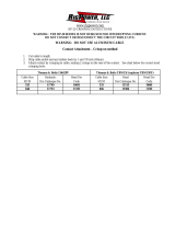
Contact Attachment – Crimp-on method
1. Cut each cable to length. Strip the end of the cable jacket and any binders back by 1-7/8 inch (48mm).
2. Insert wire and attach contact by crimping to cable, accurately making the crimps on the undercut portions of the
contact.
3. See Table below for correct Crimping Tool, Dies, and number of crimps for each contact size.
WARNING: Ensurethatgenderofcontactmatchesgenderofinsulator: RMP®II/RMP®IIISERIESCONTACTSLOCKVERY
SECURELYANDAREEXTREMELYDIFFICULTTOREMOVEWHENLOCKEDINTOTHEINSULATORBOOT.
Crimping Information:
Burndy Crimp Tool: Y750BH or PAT750 LI
Cable Size
MCM
Hydraulic Die
Catalogue No.
Head Die
Code
Number of
Crimps
4/0 AWG,
262 & 313 RP76 RP76 1
373 & 444 RP99H RP99H 2
535 RP106H RP106H 2
646 & 777 RP115H RP115H 2
Thomas & Betts Crimp Tool: 13642PF Thomas & Betts Crimp Tool: TBM15I (replaces TBM15PF)
Cable Size
MCM
Hydraulic Die
Catalogue No.
Head Die
Code
Number of
Crimps
Cable Size
MCM
Head Die
Catalogue No.
Head Die
Code
Number of
Crimps
4/0 AWG,
262 & 313 11744 76H 2
4/0 AWG,
262 & 313 15512 76H 2
373 & 444 11748 99H 2 373 & 444 15505 99H 2
535 11749 106H 2 535 15515 106H 2
646 & 777 11753 115H 2 646 & 777 15504 115H 2
Contact Attachment – Solder Attachment
1. Cut cable to length. Strip the end of the cable jacket and any binders back by 1 and 7/8 inch (48mm).
2. Attach contact by soldering, using Rosin Flux and 40 – 60 solder. Do not use excessive heat or contact will be distorted
and protective plating will be damaged.

P/N KIL00921489 FORM NO. K1489 R09/21 ECO-R-013-21 Page 3 of 4
2112 Fenton Logistics Blvd
Fenton, MO 63026
T: 281-560-2104
RMP® II / RMP® III SERIES SINGLE‐POLECONNECTORS
INSTALLATION INSTRUCTIONS (Continued)
Installation of Insulator "Boot":
WARNING: DoNOTattempttoinstallinsulatorunlessspringretainerisinplaceoncontact.THEHOSECLAMPISFOR
PREVENTIONOFMOISTUREENTRYONLYANDWILLNOTPROVIDEADEQUATECONTACTRETENTION.
WARNING: IFassemblingsmallerdiameterconductors(4/0,262,313),PROCEEDTOSPECIALINSTRUCTIONSON
PAGE4.DONOTINSTALLTHEINSULATORBOOTUNTILYOUHAVEAPPLIEDTHEHEAT‐SHRINKTUBING.Whenused
outdoorsorinwetlocations,thesesmallerconductorsizesrequireheat‐shrinktubingtobeinstalledovertheconductor
jacketatthepointwherethehose‐clampwillsealtheinsulatortotheconductor.HEAT‐SHRINKKITSWITHSPECIAL
INSTALLATIONINSTRUCTIONSareprovidedforassemblyofthosethreecablesizes.IfyourequireaHeat‐ShrinkTubingKitora
Hose‐clamp,pleasecontactCustomerServiceat800-354-9189.
1. Measure 5 ¼ inches back from contact alignment pins and wrap one or two layers of neoprene tape over cable
jacket to ensure a tight seal between cable OD and insulator ID.
2. Slide the RMP® II / RMP® III insulator over the contact / conductor assembly. Each contact has two contact
retention pins. These pins are to be aligned with the “U” slots in the retention ring inside the insulator. To aid assembly,
the “U” slots line up with the two flattened label areas on the outside of the insulator. Push the insulator over contact until
the pins hit the metal retention ring inside the insulator. (NOTE - Use only Silicone spray products if lubricant is necessary
for Step 7.
DO NOT use grease or wire-pulling compound as this may cause oxidation if left on the contact surface).
3. If necessary, rotate insulator while pushing against cable until pins align with, and snap into, the u-shaped openings
in the metal retention ring. When inserted correctly, the retaining spring locks behind the contact retention ring to hold
the contact in position and insulator will not rotate on contact. Ensure that retainer ring is securely locked into metal
ring inside of insulator.
4. After installation of the cable/contact assembly into the insulator boot, the insulator must be "sealed" by clamping to
the cable using the supplied hose clamp. UL TYPE 4 and IP66/68 ratings only apply when the hose clamp is used.
Smaller diameter conductors (4/0, 262, 313) require heat-shrink tubing to be installed between the conductor and insulator
to carry those ratings. Kits are provided with special installation instructions (BELOW) for assembly to those cable sizes.
WARNING: Toensureadequatecontactretention,ensurethepinsarefullyseatedandthatthespringlocksareengagedbehind
theretainerring.THEHOSECLAMPALONEDOESNOTPROVIDEADEQUATECONTACTRETENTION.
Connection of Male to Receptacles and Female Cord-Connectors :
WHENUSEDINCLASSI,DIVISION2CLASSIFIEDHAZARDOUSAREAS(Canada):

P/N KIL00921489 FORM NO. K1489 R09/21 ECO-R-013-21 Page 4 of 4
2112 Fenton Logistics Blvd
Fenton, MO 63026
T: 281-560-2104
WARNING: Thereceptacle/cord‐connectorset‐screwmustbetightened(hand‐tight)aftertheconnectorsarefullymatedwhenthe
devicesareusedinClassI,Division2HazardousLocations.Failuretodosocouldpresentanexplosionhazard.
RMPII/RMPIIISERIES SINGLE‐POLECONNECTORS
SPECIAL INSTALLATION INSTRUCTIONS
FOR SMALLER DIAMETER CONDUCTORS
Installation of Conductor, Heat-Shrink Tubing and Insulator
WHEN USED WITH 4/0 AWG, 262 MCM and 313 MCM Type P or DLO CABLE**
** - Note: For Hazardous Locations applications, only Type DLO Cable is permitted
(Type P “Shipboard” cable is not recognized by the Canadian Electrical Code for use in HazLoc)
1. Slide the Hose Clamp over the Cable.
2. Slide two pieces of Heat-shrink tubing over 4/0 AWG cable, or slide one piece of Heat Shrink tubing over 262 MCM
or 313 MCM cable.
3. Install the cable into the contact wire connector and crimp with Burndy or Thomas & Betts tool and die sets as
described on Page 2 above.
4. Once the conductor is installed and properly crimped into the wire connector, measure 5 ¼ inches back from
contact alignment pins and mark the conductor.
5. Center one piece of heat-shrink over the 5-1/4 inch mark on the conductor and shrink/adhere it (to create a thicker
conductor jacket where the insulator will eventually be clamped) using a heat-gun. Apply heat to the Heat-shrink
tubing until it shrinks down snugly onto the conductor insulation. Be sure the heat-shrink tubing is completely
adhered to the conductor insulation, and is allowed to cure, before moving on to Step 6 (for 4/0 AWG) or
Step 7 (for 262 MCM and 313 MCM) below.
6. Slide the RMPII / RMPIII insulator over the contact / conductor assembly. Each contact has two contact retention
pins. These pins are to be aligned with the “U” slots in the retention ring inside the insulator. To aid assembly, the
“U” slots line up with the two flattened label areas on the outside of the insulator. Push the insulator over contact
until the pins hit the metal retention ring inside the insulator. (NOTE - Use only Silicone spray products if a
lubricant is necessary for Step 7. DO NOT use grease or wire-pulling compound as this may cause oxidation
if left on the contact surface).
7. If necessary, rotate insulator while pushing against cable until pins align with, and snap into, the u-shaped openings
in the metal retention ring. When inserted correctly, the retaining spring locks behind the contact retention ring to
hold the contact in position and insulator will not rotate on contact. Ensure that retainer ring is securely locked into
metal ring inside of insulator.
8. Slide the hose clamp over the Heat-shrink and onto the insulator until it is in the narrow area of the insulator and
tighten hose-clamp screw to 25 lb-ins.
/