Page is loading ...

USER’S MANUAL
VS
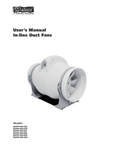
Duct centrifugal fan in sound insulated casing

2
VS
www.ventilation-system.com
CONTENTS
This user’s manual is a main operating document intended for technical, maintenance, and operating staff.
The manual contains information about purpose, technical details, operating principle, design, and installation of the VS unit and all its
modifications.
Technical and maintenance staff must have theoretical and practical training in the field of ventilation systems and should be able to
work in accordance with workplace safety rules as well as construction norms and standards applicable in the territory of the country.
The information in this user’s manual is correct at the time of the document’s preparation.
The Company reserves the right to modify the technical characteristics, design, or configuration of its products at any time in order to
incorporate the latest technological developments.
No part of this publication may be reproduced, stored in a retrieval system, or transmitted, in any form or by any means in any information
search system or translated into any language in any form without the prior written permission of the Company.
Safety requirements ..................................................................................................................................................................... 3
Purpose ................................................................................................................................................................................................ 5
Delivery set ........................................................................................................................................................................................ 5
Designation key .............................................................................................................................................................................. 5
Technical data .................................................................................................................................................................................. 6
Design and functioning ............................................................................................................................................................ 9
Mounting and set-up .................................................................................................................................................................. 10
Connection to power mains .................................................................................................................................................. 11
Commissioning ............................................................................................................................................................................... 16
Technical maintenance .............................................................................................................................................................. 16
Troubleshooting .............................................................................................................................................................................17
Storage and transportation regulations .......................................................................................................................... 17
Product sales .................................................................................................................................................................................... 17
Manufacturer’s warranty ........................................................................................................................................................... 18
Certificate of acceptance .......................................................................................................................................................... 19
Seller information .......................................................................................................................................................................... 19
Installation certificate .................................................................................................................................................................. 19
Warranty card ................................................................................................................................................................................... 19

3
www.ventilation-system.com
SAFETY REQUIREMENTS
All user’s manual requirements as well as the provisions of all the applicable local and national
construction, electrical, and technical norms and standards must be observed when installing
and operating the unit.
Disconnect the unit from power supply prior to any connection, servicing, maintenance, and
repair operations.
Only qualied electricians with a work permit for electrical units up to 1000 V are
allowed for installation and maintenance. The present user’s manual should be carefully
read before beginning works.
• Single-phase power mains must comply with the acting local electrical norms and standards.
• Fixed electrical wiring must be equipped with an automatic circuit breaker.
• The unit must be connected to power mains through a double pole circuit breaker of suitable
rating integrated into the fixed wiring system with opening of contacts at all poles. The gap
between the circuit breaker contacts at all poles must be not less than 3 mm.
• If the supply cord is damaged, it must be replaced by a special cord or assembly available
from the manufacturer or its service agent.
• Check the unit for any visible damage of the impeller, the casing, and the grille before starting
installation. The casing internals must be free of any foreign objects that can damage the
impeller blades.
• While mounting the unit, avoid compression of the casing! Deformation of the casing may
result in motor jam and excessive noise.
• Misuse of the unit and any unauthorized modifications are not allowed.
• Do not expose the device to adverse atmospheric agents (rain, sun, etc.).
• Take steps to prevent ingress of smoke, carbon monoxide, and other combustion products
into the room through open chimney flues or other fire-protection devices. Sufficient air
supply must be provided for proper combustion and exhaust of gases through the chimney
of fuel burning equipment to prevent back drafting.
• Transported air must not contain any dust or other solid impurities, sticky substances, or
fibrous materials.
• Do not use the unit in a hazardous or explosive environment containing spirits, gasoline,
insecticides, etc.
• For effective functioning of the unit, it is necessary to ensure an appropriate fresh air supply
into the room. Do not close or block the intake or extract vents in order to ensure the efficient
air flow.
• Do not sit on the unit and do not put objects on it.
• The unit is allowed to be used by children aged from 8 years old and above and persons with
reduced physical, sensory, or mental capabilities or no experience and knowledge provided
that they have been given supervision or instruction regarding safe use of the unit and
understand the risks involved.
• Do not allow children to play with the unit.
• Cleaning and user maintenance shall not be made by children without supervision.
• The information in this user’s manual was correct at the time of the document’s preparation.

4
VS
www.ventilation-system.com
THE PRODUCT MUST BE DISPOSED SEPARATELY AT THE END OF ITS SERVICE LIFE.
DO NOT DISPOSE THE UNIT AS UNSORTED DOMESTIC WASTE.
• The Company reserves the right to modify the technical characteristics, design, or
configuration of its products at any time in order to incorporate the latest technological
developments.
• No part of this publication may be reproduced, stored in a retrieval system, or transmitted, in
any form or by any means in any information search system or translated into any language in
any form without the prior written permission of the Company.
WARNING! Similar to the use of any other household electrical appliances when
operating this fan, the following basic rules must be followed:
• Never touch the fan with wet or damp hands.
• Never touch the fan when barefoot.

5
www.ventilation-system.com
THE UNIT SHOULD NOT BE OPERATED BY CHILDREN OR PERSONS WITH REDUCED
PHYSICAL, MENTAL, OR SENSORY CAPACITIES, OR THOSE WITHOUT THE APPROPRIATE
TRAINING.
THE UNIT MUST BE INSTALLED AND CONNECTED ONLY BY PROPERLY QUALIFIED
PERSONNEL AFTER THE APPROPRIATE BRIEFING.
THE CHOICE OF UNIT INSTALLATION LOCATION MUST PREVENT UNAUTHORIZED
ACCESS BY UNATTENDED CHILDREN.
DESIGNATION KEY
The duct centrifugal fan in sound insulated casing is designed for supply and exhaust ventilation of domestic, public and industrial
premises with high requirements to the noise level and with limited space for mounting.
The unit is rated for continuous operation.
The unit is a component part and is not designed for stand-alone operation.
Transported air must not contain any flammable or explosive mixtures, evaporation of chemicals, sticky substances, fibrous materials,
coarse dust, soot and oil particles or environments favourable for the formation of hazardous substances (toxic substances, dust,
pathogenic germs).
NAME NUMBER
Fan 1 pc.
User's manual 1 pc.
Packing box 1 pc.
PURPOSE
DELIVERY SET
VS 630 __ S 4E
Name
VS – noise-insulated fan
Diameter
Turbine size [mm]
Electric motor type
_ – AC by default
EC – electronically commutated
Options:
_ – by default
S – high-powered motor
Q – low-noise and low-power
Polarity
_ – not specified by default for EC motors
Number of poles [4, 6]
Phases
_ – not specified by default for EC motors
E – single-phase
D – three-phase

6
VS
www.ventilation-system.com
The fan is designed for operation in an enclosed area at ambient temperatures from -25 °C up to +60 °C.
The fan is rated as a class I electric appliance.
The fan design is regularly improved, thus some models may slightly differ from those ones described herein.
Ingress protection rating against access to hazardous parts and water ingress is IPX4.
Parameter VS 355 4E VS 355 4D VS 400 4E VS 400 4D
Voltage [V] 1~ 230 3~ 400 Y 1~ 230 3~ 400 Δ
Frequency [Hz] 50 50 60 50 60 50 60
Power [W] 245 230 235 480 700 515 750
Current [A] 1.12 0.52 0.53 2.4 3.15 1.41 1.44
Maximum air flow [m
3
/h]
perpendicularly 2890 2660 2815 3750 4310 3950 4310
directly 2650 2380 2580 3535 4015 3740 4055
RPM [min
-1
]
1420 1400 1600 1370 1460 1415 1610
Sound pressure level at 3 m
distance [dBA]
54 53 55 51 52 51 53
Transported air temperature [°С] -25...+50 -25...+70 -25...+65 -40...+80 -40...+55 -40...+60 -40...+60
Parameter VS 400 4D VS 450 4E VS 450 4D VS 500 4E VS 500 4D VS 560 4D
Voltage [V] 3~ 400 Y 1~ 230 3~ 400 1~ 230 3~ 400 3~ 400
Frequency [Hz] 50 60 50 50 50 50 50
Power [W] 385 515 680 740 1300 1430 2380
Current [A] 0.7 0.93 3 1.5 5.7 3 5
Maximum air flow [m
3
/h]
perpendicularly 3340 3525 5630 5700 7330 7940 11340
directly 3110 3290 4930 5080 6680 7200 10490
RPM [min
-1
]
1235 1220 1250 1350 1320 1375 1365
Sound pressure level at 3 m
distance [dBA]
47 49 53 54 55 58 56
Transported air temperature [°С] -40...+80 -40...+40 -40...+70 -40...+80 -20...+50 -40...+80 -40...+60
Parameter VS 560 6D VS 630 4D VS 630 S 4D VS 630 6D VS 710 6D
Voltage [V] 3~ 400 3~ 400 3~ 400 3~ 400 3~ 400
Frequency [Hz] 50 50 50 50 50
Power [W] 780 3310 4250 1310 2000
Current [A] 1.7 6.2 7.55 2.8 3.9
Maximum air flow [m
3
/h]
perpendicularly 7970 15170 16870 12030 15830
directly 7330 13740 14930 10440 14880
RPM [min
-1
]
885 1170 1300 880 890
Sound pressure level at 3 m
distance [dBA]
49 67 69 55 59
Transported air temperature [°С] -40...+55 -40...+35 -40...+60 -40...+60 -20...+40
3~400 Δ – with delta connection. 3~400 Y – with star connection.
TECHNICAL DATA

7
www.ventilation-system.com
Parameter VS 315 VS 355 VS 400 VS 450 VS 500 VS 560 VS 630
Voltage [V] 1~200-240 1~200-277 1~200-277 1~200-277 3~380-480 3~380-480 3~380-480
Power [W] 150 250 500 750 1320 2360 2750
Current [A] 1.23 1.1 2.2 3.3 2.1 3.65 4.3
Maximum air flow [m
3
/h]
perpendicularly 2370 3830 5660 6800 10450 13600 16740
directly 2252 3639 5377 6460 9928 12920 15903
RPM [min
-1
]
1600 1450 1500 1440 1350 1540 1300
Sound pressure level at 3 m
distance [dBA]
35 44 39 50 45 50 50
Transported air temperature [°С] -40...+80 -25...+60 -25...+50 -25...+60 -20...+50 -25...+60 -25...+55
Model
Dimensions [mm]
H A B
VS 315. 355 500 310 460
VS 400. 450. 500 670 480 630
VS 560. 630 800 610 760
VS 710 1000 810 960
H
A
A
H
B
B
Options for fans Dimensions [mm]
VPG VVG A B C ØD F
VPG 500/355 VVG 500х500 490 460 310 354 470
VPG 670/400
VVG 670х670 660 630 480
399
640VPG 670/450 449
VPG 670/500 499
VPG 800/560
VVG 800х800 790 760 610
559
770
VPG 800/630 629
VPG 1000/710 VVG 1000х1000 990 960 810 709 970
A
350
øD
F
B
C
A
F
C
B
120

8
VS
www.ventilation-system.com
Options for fans Dimensions [mm]
KN-VS A B C D H h
KN-VS 315-355 478 458 310 460 225 75
KN-VS 400-500 648 628 480 630 321 108
KN-VS 560-630 778 758 610 760 421 141
KN-VS 710 978 959 810 960 422 141
D
h
H
A
B C
Options for fans Dimensions [mm]
VPR-VS A C D H
VPR-VS 315-355 600 310 460 11
VPR-VS 400-500 770 480 630 11
VPR-VS 560-630 900 610 760 11
VPR-VS 710 1100 810 960 11
A
D
C
H

9
www.ventilation-system.com
The fan casing is made of an aluminium frame, fastened with aluminium angles, and removable heat and sound insulating two-layer
aluzinc panels.
Due to a casing made of aluzinc with increased corrosion-resistant properties and a heat-insulating material, the fan can be used for
outdoor installation.
The VS fan is equipped with a four- or six-pole AC motor with an external rotor and an impeller with backward curved blades.
The VS EC fan is equipped with a maintenance-free EC motor with an external rotor and an impeller with backward curved blades.
The fan has a special design that allows changing the position of the side panels for air supply in all directions, both linearly and at an
angle of 90°.
The VS fans may be used for construction of various configurations of ventilation systems.
Motor
Frame
Panel
Terminal box
Linear connection of air ducts Air duct connection at 90°
The spigots, which also function as vibration damping inserts, can be of square or round cross-section.
The round spigots are rubber sealed.
The connecting spigots are not included in the delivery set and can be ordered separately.
DESIGN AND FUNCTIONING

10
VS
www.ventilation-system.com
Before installing the fan, make sure that there is no visible damage to the impeller, check the integrity of the insulation of the supply wires.
Make sure the impeller rotates freely without touching the flange and the casing.
The fan shall be installed in the air duct with the same diameter.
Mount the fan in such a way that the arrow on the fan casing matches the air flow direction in the system.
The fans are installed between the air ducts.
The connection to the air ducts is carried out using an appropriately sized connecting spigot.
In case of mounting the fan on flexible joints, attach the fan to a structural unit by means of supports, suspension links or brackets.
The fan may be installed in any position in consideration of the air flow direction (as indicated by the arrow on the fan casing).
To attain the best performance of the fan and to minimize turbulence-induced air pressure losses while mounting, connect the straight
air duct section to the fan spigots on both sides of the fan. The minimum straight air duct length is equal to 1 air duct diameter on the
intake side and 3 air duct diameters on the exhaust side.
No filters or any other similar devices are allowed to be installed in these sections.
The fan is not a ready to use unit and requires connection to the air ducts.
Install the fan securely while ensuring free access for maintenance operations, the required distance to the walls of the room is at least
1 m.
Fan installation sequence:
• Before installation, lay the wires and cables necessary to connect the fan to power mains.
• Make sure that the fan is disconnected from power mains.
• Mark the positions for mounting the fixing brackets on the load-bearing surface.
• Fix the fan on the mounting brackets using the appropriate fasteners (for example, dowels).
• Connect the air ducts to the fan.
Mounting on threaded rods
fixed in threaded dowels
The fan can be fixed on a
horizontal plane
When installed outdoors, the fan can be equipped with a VPR-VS
protective hood and (or) a KN-VS outer hood
VPR-VS KN-VS
The VPR-VS protective hood and the KN-VS outer hood are not included in the delivery set and must be ordered separately.
WHILE INSTALLING THE UNIT ENSURE CONVENIENT ACCESS FOR SUBSEQUENT
MAINTENANCE AND REPAIR.
BEFORE MOUNTING MAKE SURE THE CASING DOES NOT CONTAIN ANY FOREIGN
OBJECTS E.G. FOIL, PAPER.
MOUNTING AND SETUP

11
www.ventilation-system.com
DISCONNECT THE POWER SUPPLY PRIOR TO ANY OPERATIONS WITH THE UNIT.
CONNECTION OF THE UNIT TO POWER MAINS IS ALLOWED BY A QUALIFIED
ELECTRICIAN WITH A WORK PERMIT FOR THE ELECTRIC UNITS UP TO 1000 V AFTER
CAREFUL READING OF THE PRESENT USER’S MANUAL. THE RATED ELECTRICAL
PARAMETERS OF THE UNIT ARE GIVEN ON THE MANUFACTURER’S LABEL.
• The unit is rated for connection to 1~230 V/50 (60) Hz power mains according to the corresponding wiring diagram.
• The connection must be made using durable, insulated and heat-resistant conductors (cables, wires). The actual wire cross section
selection must be based on the maximum load current, maximum conductor temperature depending on the wire type, insulation,
length and installation method.
• Connection of the unit to the fixed power supply network must be carried out in accordance with the current regulations.
Connect the cables to the terminal block incorporated inside the terminal box located on the fan casing in compliance with the fan
wiring diagram and the terminal designation.
The terminal designations are shown on the label inside the fan casing.
Power supply parameters and examples of wiring diagrams depending on the unit model
VS 355 4E VS 400 4E, VS 450 4E VS 500 4E
L
N
X1
1
2
3
N
L
QF
PE
~230 V
Hz50
4
1
2
5
6
3
4
1
2
5
6
7
3
4
РЕ
L
N
X1
N
L
QF
PE
~230 V
Hz50
TW1
TW2
TW1
TW2
TW1
TW2
TW1
TW2
TW1
TW2
TW1
TW2
W2
W1
V2
TW1
TW2
РЕ
L
N
X1
N
L
QF
PE
~230 V
Hz50
РЕ
Х 2
NC
COM
Х1
1
2
3
4
PE
L1
L2
L3
5
1
2
3
4
5
6
NC
COM
QF
L1
L2
L3
PE
~380 V
Hz50
L2
L1
QF
PE
~400V
Hz50
L2
L1
X1
2
7
1
3
L3
L3
5
4
6
V1
U1
PE
U2
TW1
TW2
W2
W1
V2
V1
U1
PE
U2
L1
L2
L3
8
9
РЕ
L2
L1
QF
PE
~400 V
Hz50
L2
L1
X1
2
7
1
3
2
1
3
2
1
3
L3
L3
5
4
6
L1
L2
L3
8
9
TW2
TW1
TW1
TW2
PE
L
QF
~230 V
Hz50
N
L
X1
PE
N
PE
+10V
0-10V
GND
+10V
CTR
GND
+10V
CTR
GND
+10V
CTR
GND
X2
QF
PE
N
L
Х 1
~230 V
Hz50/60
1
2
3
4
5
PE
N
L
Х2
1
2
3
4
5
0-10V
RSB
RSA
GND
+10V
0-10V
RSB
RSA
GND
+10V
KL1
PE
L3
~400 V
50 Hz
QF
KL3
+20 V
0-10 V
RSA
RSB
RSA
RSB
GND
4-20 mA
+10 V
0-10 V
GND
OUT
KL2
NO
COM
NC
L1
L2
L2
L1
L3
PE
Подключение аналогового выхода
0-10 V прибора управления
0-10 V GND
KL3
Подключение релейного выхода
прибора управления
0-10 V +10 V
KL3KL3
Подключение регулятора
(потенциометра)
0-10 V GND+10 V
Подключение датчика
критического давления 4-20 mA
4-20 mA +20 V
KL3
Схема внешних подключений и универсального соединения вентиляторов с ЕС-двигателями в группу
L
N
X1
X1
1
2
3
L
QF
N
PE
TW1
4
5
6
TW2
~230 V
Hz50
KM1
S1
“ON”
S2
“OFF”
KM1
РЕ
L1
TW1
TW2
S1
“ON”
S2
“OFF”
KM1
L2
L3
QF
~400 V
Hz50
L1
L2
L3
N
PE
PE
L
N
X1
1
2
3
N
L
QF
PE
~230 V
Hz50
4
1
2
5
6
3
4
1
2
5
6
7
3
4
РЕ
L
N
X1
N
L
QF
PE
~230 V
Hz50
TW1
TW2
TW1
TW2
TW1
TW2
TW1
TW2
TW1
TW2
TW1
TW2
W2
W1
V2
TW1
TW2
РЕ
L
N
X1
N
L
QF
PE
~230 V
Hz50
РЕ
Х 2
NC
COM
Х1
1
2
3
4
PE
L1
L2
L3
5
1
2
3
4
5
6
NC
COM
QF
L1
L2
L3
PE
~380 V
Hz50
L2
L1
QF
PE
~400V
Hz50
L2
L1
X1
2
7
1
3
L3
L3
5
4
6
V1
U1
PE
U2
TW1
TW2
W2
W1
V2
V1
U1
PE
U2
L1
L2
L3
8
9
РЕ
L2
L1
QF
PE
~400 V
Hz50
L2
L1
X1
2
7
1
3
2
1
3
2
1
3
L3
L3
5
4
6
L1
L2
L3
8
9
TW2
TW1
TW1
TW2
PE
L
QF
~230 V
Hz50
N
L
X1
PE
N
PE
+10V
0-10V
GND
+10V
CTR
GND
+10V
CTR
GND
+10V
CTR
GND
X2
QF
PE
N
L
Х 1
~230 V
Hz50/60
1
2
3
4
5
PE
N
L
Х2
1
2
3
4
5
0-10V
RSB
RSA
GND
+10V
0-10V
RSB
RSA
GND
+10V
KL1
PE
L3
~400 V
50 Hz
QF
KL3
+20 V
0-10 V
RSA
RSB
RSA
RSB
GND
4-20 mA
+10 V
0-10 V
GND
OUT
KL2
NO
COM
NC
L1
L2
L2
L1
L3
PE
Подключение аналогового выхода
0-10 V прибора управления
0-10 V GND
KL3
Подключение релейного выхода
прибора управления
0-10 V +10 V
KL3KL3
Подключение регулятора
(потенциометра)
0-10 V GND+10 V
Подключение датчика
критического давления 4-20 mA
4-20 mA +20 V
KL3
Схема внешних подключений и универсального соединения вентиляторов с ЕС-двигателями в группу
L
N
X1
X1
1
2
3
L
QF
N
PE
TW1
4
5
6
TW2
~230 V
Hz50
KM1
S1
“ON”
S2
“OFF”
KM1
РЕ
L1
TW1
TW2
S1
“ON”
S2
“OFF”
KM1
L2
L3
QF
~400 V
Hz50
L1
L2
L3
N
PE
PE
VS 355 4D, VS 450 4D, VS 500 4D,
VS 560 4D, VS 560 6D, VS 630 4D,
VS 630 S 4D, VS 630 6D, VS 710 6D
VS 400 4D VS 315 ЕС
L
N
X1
1
2
3
N
L
QF
PE
~230 V
Hz50
4
1
2
5
6
3
4
1
2
5
6
7
3
4
РЕ
L
N
X1
N
L
QF
PE
~230 V
Hz50
TW1
TW2
TW1
TW2
TW1
TW2
TW1
TW2
TW1
TW2
TW1
TW2
W2
W1
V2
TW1
TW2
РЕ
L
N
X1
N
L
QF
PE
~230 V
Hz50
РЕ
Х 2
NC
COM
Х1
1
2
3
4
PE
L1
L2
L3
5
1
2
3
4
5
6
NC
COM
QF
L1
L2
L3
PE
~380 V
Hz50
L2
L1
QF
PE
~400V
Hz50
L2
L1
X1
2
7
1
3
L3
L3
5
4
6
V1
U1
PE
U2
TW1
TW2
W2
W1
V2
V1
U1
PE
U2
L1
L2
L3
8
9
РЕ
L2
L1
QF
PE
~400 V
Hz50
L2
L1
X1
2
7
1
3
2
1
3
2
1
3
L3
L3
5
4
6
L1
L2
L3
8
9
TW2
TW1
TW1
TW2
PE
L
QF
~230 V
Hz50
N
L
X1
PE
N
PE
+10V
0-10V
GND
+10V
CTR
GND
+10V
CTR
GND
+10V
CTR
GND
X2
QF
PE
N
L
Х 1
~230 V
Hz50/60
1
2
3
4
5
PE
N
L
Х2
1
2
3
4
5
0-10V
RSB
RSA
GND
+10V
0-10V
RSB
RSA
GND
+10V
KL1
PE
L3
~400 V
50 Hz
QF
KL3
+20 V
0-10 V
RSA
RSB
RSA
RSB
GND
4-20 mA
+10 V
0-10 V
GND
OUT
KL2
NO
COM
NC
L1
L2
L2
L1
L3
PE
Подключение аналогового выхода
0-10 V прибора управления
0-10 V GND
KL3
Подключение релейного выхода
прибора управления
0-10 V +10 V
KL3KL3
Подключение регулятора
(потенциометра)
0-10 V GND+10 V
Подключение датчика
критического давления 4-20 mA
4-20 mA +20 V
KL3
Схема внешних подключений и универсального соединения вентиляторов с ЕС-двигателями в группу
L
N
X1
X1
1
2
3
L
QF
N
PE
TW1
4
5
6
TW2
~230 V
Hz50
KM1
S1
“ON”
S2
“OFF”
KM1
РЕ
L1
TW1
TW2
S1
“ON”
S2
“OFF”
KM1
L2
L3
QF
~400 V
Hz50
L1
L2
L3
N
PE
PE
L
N
X1
1
2
3
N
L
QF
PE
~230 V
Hz50
4
1
2
5
6
3
4
1
2
5
6
7
3
4
РЕ
L
N
X1
N
L
QF
PE
~230 V
Hz50
TW1
TW2
TW1
TW2
TW1
TW2
TW1
TW2
TW1
TW2
TW1
TW2
W2
W1
V2
TW1
TW2
РЕ
L
N
X1
N
L
QF
PE
~230 V
Hz50
РЕ
Х 2
NC
COM
Х1
1
2
3
4
PE
L1
L2
L3
5
1
2
3
4
5
6
NC
COM
QF
L1
L2
L3
PE
~380 V
Hz50
L2
L1
QF
PE
~400V
Hz50
L2
L1
X1
2
7
1
3
L3
L3
5
4
6
V1
U1
PE
U2
TW1
TW2
W2
W1
V2
V1
U1
PE
U2
L1
L2
L3
8
9
РЕ
L2
L1
QF
PE
~400 V
Hz50
L2
L1
X1
2
7
1
3
2
1
3
2
1
3
L3
L3
5
4
6
L1
L2
L3
8
9
TW2
TW1
TW1
TW2
PE
L
QF
~230 V
Hz50
N
L
X1
PE
N
PE
+10V
0-10V
GND
+10V
CTR
GND
+10V
CTR
GND
+10V
CTR
GND
X2
QF
PE
N
L
Х 1
~230 V
Hz50/60
1
2
3
4
5
PE
N
L
Х2
1
2
3
4
5
0-10V
RSB
RSA
GND
+10V
0-10V
RSB
RSA
GND
+10V
KL1
PE
L3
~400 V
50 Hz
QF
KL3
+20 V
0-10 V
RSA
RSB
RSA
RSB
GND
4-20 mA
+10 V
0-10 V
GND
OUT
KL2
NO
COM
NC
L1
L2
L2
L1
L3
PE
Подключение аналогового выхода
0-10 V прибора управления
0-10 V GND
KL3
Подключение релейного выхода
прибора управления
0-10 V +10 V
KL3KL3
Подключение регулятора
(потенциометра)
0-10 V GND+10 V
Подключение датчика
критического давления 4-20 mA
4-20 mA +20 V
KL3
Схема внешних подключений и универсального соединения вентиляторов с ЕС-двигателями в группу
L
N
X1
X1
1
2
3
L
QF
N
PE
TW1
4
5
6
TW2
~230 V
Hz50
KM1
S1
“ON”
S2
“OFF”
KM1
РЕ
L1
TW1
TW2
S1
“ON”
S2
“OFF”
KM1
L2
L3
QF
~400 V
Hz50
L1
L2
L3
N
PE
PE
Recommended
controller VENTS
R-1/010
CONNECTION TO POWER MAINS

12
VS
www.ventilation-system.com
VS 355 ЕС, VS 400 ЕС, VS 450 ЕС VS 500 ЕС VS 560 ЕС, VS 630 ЕС, VS 630 S ЕС
L
N
X1
1
2
3
N
L
QF
PE
~230 V
Hz50
4
1
2
5
6
3
4
1
2
5
6
7
3
4
РЕ
L
N
X1
N
L
QF
PE
~230 V
Hz50
TW1
TW2
TW1
TW2
TW1
TW2
TW1
TW2
TW1
TW2
TW1
TW2
W2
W1
V2
TW1
TW2
РЕ
L
N
X1
N
L
QF
PE
~230 V
Hz50
РЕ
Х 2
NC
COM
Х1
1
2
3
4
PE
L1
L2
L3
5
1
2
3
4
5
6
NC
COM
QF
L1
L2
L3
PE
~380 V
Hz50
L2
L1
QF
PE
~400V
Hz50
L2
L1
X1
2
7
1
3
L3
L3
5
4
6
V1
U1
PE
U2
TW1
TW2
W2
W1
V2
V1
U1
PE
U2
L1
L2
L3
8
9
РЕ
L2
L1
QF
PE
~400 V
Hz50
L2
L1
X1
2
7
1
3
2
1
3
2
1
3
L3
L3
5
4
6
L1
L2
L3
8
9
TW2
TW1
TW1
TW2
PE
L
QF
~230 V
Hz50
N
L
X1
PE
N
PE
+10V
0-10V
GND
+10V
CTR
GND
+10V
CTR
GND
+10V
CTR
GND
X2
QF
PE
N
L
Х 1
~230 V
Hz50/60
1
2
3
4
5
PE
N
L
Х2
1
2
3
4
5
0-10V
RSB
RSA
GND
+10V
0-10V
RSB
RSA
GND
+10V
KL1
PE
L3
~400 V
50 Hz
QF
KL3
+20 V
0-10 V
RSA
RSB
RSA
RSB
GND
4-20 mA
+10 V
0-10 V
GND
OUT
KL2
NO
COM
NC
L1
L2
L2
L1
L3
PE
Подключение аналогового выхода
0-10 V прибора управления
0-10 V GND
KL3
Подключение релейного выхода
прибора управления
0-10 V +10 V
KL3KL3
Подключение регулятора
(потенциометра)
0-10 V GND+10 V
Подключение датчика
критического давления 4-20 mA
4-20 mA +20 V
KL3
Схема внешних подключений и универсального соединения вентиляторов с ЕС-двигателями в группу
L
N
X1
X1
1
2
3
L
QF
N
PE
TW1
4
5
6
TW2
~230 V
Hz50
KM1
S1
“ON”
S2
“OFF”
KM1
РЕ
L1
TW1
TW2
S1
“ON”
S2
“OFF”
KM1
L2
L3
QF
~400 V
Hz50
L1
L2
L3
N
PE
PE
Recommended
controller VENTS
R-1/010
Alarm
relay
L
N
X1
1
2
3
N
L
QF
PE
~230 V
Hz50
4
1
2
5
6
3
4
1
2
5
6
7
3
4
РЕ
L
N
X1
N
L
QF
PE
~230 V
Hz50
TW1
TW2
TW1
TW2
TW1
TW2
TW1
TW2
TW1
TW2
TW1
TW2
W2
W1
V2
TW1
TW2
РЕ
L
N
X1
N
L
QF
PE
~230 V
Hz50
РЕ
Х 2
NC
COM
Х1
1
2
3
4
PE
L1
L2
L3
5
1
2
3
4
5
6
NC
COM
QF
L1
L2
L3
PE
~380 V
Hz50
L2
L1
QF
PE
~400V
Hz50
L2
L1
X1
2
7
1
3
L3
L3
5
4
6
V1
U1
PE
U2
TW1
TW2
W2
W1
V2
V1
U1
PE
U2
L1
L2
L3
8
9
РЕ
L2
L1
QF
PE
~400 V
Hz50
L2
L1
X1
2
7
1
3
2
1
3
2
1
3
L3
L3
5
4
6
L1
L2
L3
8
9
TW2
TW1
TW1
TW2
PE
L
QF
~230 V
Hz50
N
L
X1
PE
N
PE
+10V
0-10V
GND
+10V
CTR
GND
+10V
CTR
GND
+10V
CTR
GND
X2
QF
PE
N
L
Х 1
~230 V
Hz50/60
1
2
3
4
5
PE
N
L
Х2
1
2
3
4
5
0-10V
RSB
RSA
GND
+10V
0-10V
RSB
RSA
GND
+10V
KL1
PE
L3
~400 V
50 Hz
QF
KL3
+20 V
0-10 V
RSA
RSB
RSA
RSB
GND
4-20 mA
+10 V
0-10 V
GND
OUT
KL2
NO
COM
NC
L1
L2
L2
L1
L3
PE
Подключение аналогового выхода
0-10 V прибора управления
0-10 V GND
KL3
Подключение релейного выхода
прибора управления
0-10 V +10 V
KL3KL3
Подключение регулятора
(потенциометра)
0-10 V GND+10 V
Подключение датчика
критического давления 4-20 mA
4-20 mA +20 V
KL3
Схема внешних подключений и универсального соединения вентиляторов с ЕС-двигателями в группу
L
N
X1
X1
1
2
3
L
QF
N
PE
TW1
4
5
6
TW2
~230 V
Hz50
KM1
S1
“ON”
S2
“OFF”
KM1
РЕ
L1
TW1
TW2
S1
“ON”
S2
“OFF”
KM1
L2
L3
QF
~400 V
Hz50
L1
L2
L3
N
PE
PE
RS 485
interface
GND
Control input
Control input
External sensor power
supply, max. 50 mA
External speed controller
power supply, max. 10 mA
Control input
GND
Control output
Alarm relay
Normally open contact
com
Normally closed contact
Designation:
L (x) – line; N – neutral; QF – circuit breaker; PE – grounding wire.
The VS EC fans are equipped with high-efficient electronically commutated motors, which are characterized by high performance and
optimal control over the entire speed range.
The efficiency of such motors reaches 90%.
Fans with EC motors must be connected to the terminal block located in the external or integrated terminal box of the electric motor in
strict accordance with the wiring diagram and terminal designation.
The terminal designations are shown on the label inside the fan casing.
The VS EC fans are controlled via various external control signals.
When the value of the control factor is changed, the EC fan changes the rotation speed and supplies as much air as is required for
the ventilation system. For example, air flow control is carried out smoothly using the recommended R-1/010 controller (hereinafter
referred to as the controller).
Speed control from zero to maximum, depending on the need.
The controller is not included in the delivery set and is connected by the consumer in accordance with the diagrams.
VS 315 ЕС VS 355 ЕС, VS 400 ЕС, VS 450 ЕС, VS 500 ЕС
L
N
X1
1
2
3
N
L
QF
PE
~230 V
Hz50
4
1
2
5
6
3
4
1
2
5
6
7
3
4
РЕ
L
N
X1
N
L
QF
PE
~230 V
Hz50
TW1
TW2
TW1
TW2
TW1
TW2
TW1
TW2
TW1
TW2
TW1
TW2
W2
W1
V2
TW1
TW2
РЕ
L
N
X1
N
L
QF
PE
~230 V
Hz50
РЕ
Х 2
NC
COM
Х1
1
2
3
4
PE
L1
L2
L3
5
1
2
3
4
5
6
NC
COM
QF
L1
L2
L3
PE
~380 V
Hz50
L2
L1
QF
PE
~400V
Hz50
L2
L1
X1
2
7
1
3
L3
L3
5
4
6
V1
U1
PE
U2
TW1
TW2
W2
W1
V2
V1
U1
PE
U2
L1
L2
L3
8
9
РЕ
L2
L1
QF
PE
~400 V
Hz50
L2
L1
X1
2
7
1
3
2
1
3
2
1
3
L3
L3
5
4
6
L1
L2
L3
8
9
TW2
TW1
TW1
TW2
PE
L
QF
~230 V
Hz50
N
L
X1
PE
N
PE
+10V
0-10V
GND
+10V
CTR
GND
+10V
CTR
GND
+10V
CTR
GND
X2
QF
PE
N
L
Х 1
~230 V
Hz50/60
1
2
3
4
5
PE
N
L
Х2
1
2
3
4
5
0-10V
RSB
RSA
GND
+10V
0-10V
RSB
RSA
GND
+10V
KL1
PE
L3
~400 V
50 Hz
QF
KL3
+20 V
0-10 V
RSA
RSB
RSA
RSB
GND
4-20 mA
+10 V
0-10 V
GND
OUT
KL2
NO
COM
NC
L1
L2
L2
L1
L3
PE
Подключение аналогового выхода
0-10 V прибора управления
0-10 V GND
KL3
Подключение релейного выхода
прибора управления
0-10 V +10 V
KL3KL3
Подключение регулятора
(потенциометра)
0-10 V GND+10 V
Подключение датчика
критического давления 4-20 mA
4-20 mA +20 V
KL3
Схема внешних подключений и универсального соединения вентиляторов с ЕС-двигателями в группу
L
N
X1
X1
1
2
3
L
QF
N
PE
TW1
4
5
6
TW2
~230 V
Hz50
KM1
S1
“ON”
S2
“OFF”
KM1
РЕ
L1
TW1
TW2
S1
“ON”
S2
“OFF”
KM1
L2
L3
QF
~400 V
Hz50
L1
L2
L3
N
PE
PE
L
N
X1
1
2
3
N
L
QF
PE
~230 V
Hz50
4
1
2
5
6
3
4
1
2
5
6
7
3
4
РЕ
L
N
X1
N
L
QF
PE
~230 V
Hz50
TW1
TW2
TW1
TW2
TW1
TW2
TW1
TW2
TW1
TW2
TW1
TW2
W2
W1
V2
TW1
TW2
РЕ
L
N
X1
N
L
QF
PE
~230 V
Hz50
РЕ
Х 2
NC
COM
Х1
1
2
3
4
PE
L1
L2
L3
5
1
2
3
4
5
6
NC
COM
QF
L1
L2
L3
PE
~380 V
Hz50
L2
L1
QF
PE
~400V
Hz50
L2
L1
X1
2
7
1
3
L3
L3
5
4
6
V1
U1
PE
U2
TW1
TW2
W2
W1
V2
V1
U1
PE
U2
L1
L2
L3
8
9
РЕ
L2
L1
QF
PE
~400 V
Hz50
L2
L1
X1
2
7
1
3
2
1
3
2
1
3
L3
L3
5
4
6
L1
L2
L3
8
9
TW2
TW1
TW1
TW2
PE
L
QF
~230 V
Hz50
N
L
X1
PE
N
PE
+10V
0-10V
GND
+10V
CTR
GND
+10V
CTR
GND
+10V
CTR
GND
X2
QF
PE
N
L
Х 1
~230 V
Hz50/60
1
2
3
4
5
PE
N
L
Х2
1
2
3
4
5
0-10V
RSB
RSA
GND
+10V
0-10V
RSB
RSA
GND
+10V
KL1
PE
L3
~400 V
50 Hz
QF
KL3
+20 V
0-10 V
RSA
RSB
RSA
RSB
GND
4-20 mA
+10 V
0-10 V
GND
OUT
KL2
NO
COM
NC
L1
L2
L2
L1
L3
PE
Подключение аналогового выхода
0-10 V прибора управления
0-10 V GND
KL3
Подключение релейного выхода
прибора управления
0-10 V +10 V
KL3KL3
Подключение регулятора
(потенциометра)
0-10 V GND+10 V
Подключение датчика
критического давления 4-20 mA
4-20 mA +20 V
KL3
Схема внешних подключений и универсального соединения вентиляторов с ЕС-двигателями в группу
L
N
X1
X1
1
2
3
L
QF
N
PE
TW1
4
5
6
TW2
~230 V
Hz50
KM1
S1
“ON”
S2
“OFF”
KM1
РЕ
L1
TW1
TW2
S1
“ON”
S2
“OFF”
KM1
L2
L3
QF
~400 V
Hz50
L1
L2
L3
N
PE
PE
The fan can be controlled using a CO2 sensor (CO2-1, CO2-2 models are recommended), from the unit’s analogue output (0-10 V) and
from the discrete output (relay contact). In the first case, the fan will smoothly increase (or decrease) the rotation speed in case of air
pollution, depending on the set CO
2
range.

13
www.ventilation-system.com
In the second case, the NO contact of the relay will turn on the fan when the set ppm level is exceeded and turn off when the minimum
set level is reached. A humidity sensor can be connected in the same way. The connection of external control devices in the integrated
terminal boxes is carried out on the KL3 terminal blocks in strict accordance with the terminal designation.
Wiring example of connecting various devices to EC motors
Connection of a 0-10 V
analogue output of the control
device
Connection of a speed
controller (potentiometer)
Connection of a control unit
relay output
Connection of a 4-20 mA
pressure sensor
L
N
X1
1
2
3
N
L
QF
PE
~230 V
Hz50
4
1
2
5
6
3
4
1
2
5
6
7
3
4
РЕ
L
N
X1
N
L
QF
PE
~230 V
Hz50
TW1
TW2
TW1
TW2
TW1
TW2
TW1
TW2
TW1
TW2
TW1
TW2
W2
W1
V2
TW1
TW2
РЕ
L
N
X1
N
L
QF
PE
~230 V
Hz50
РЕ
Х 2
NC
COM
Х1
1
2
3
4
PE
L1
L2
L3
5
1
2
3
4
5
6
NC
COM
QF
L1
L2
L3
PE
~380 V
Hz50
L2
L1
QF
PE
~400V
Hz50
L2
L1
X1
2
7
1
3
L3
L3
5
4
6
V1
U1
PE
U2
TW1
TW2
W2
W1
V2
V1
U1
PE
U2
L1
L2
L3
8
9
РЕ
L2
L1
QF
PE
~400 V
Hz50
L2
L1
X1
2
7
1
3
2
1
3
2
1
3
L3
L3
5
4
6
L1
L2
L3
8
9
TW2
TW1
TW1
TW2
PE
L
QF
~230 V
Hz50
N
L
X1
PE
N
PE
+10V
0-10V
GND
+10V
CTR
GND
+10V
CTR
GND
+10V
CTR
GND
X2
QF
PE
N
L
Х 1
~230 V
Hz50/60
1
2
3
4
5
PE
N
L
Х2
1
2
3
4
5
0-10V
RSB
RSA
GND
+10V
0-10V
RSB
RSA
GND
+10V
KL1
PE
L3
~400 V
50 Hz
QF
KL3
+20 V
0-10 V
RSA
RSB
RSA
RSB
GND
4-20 mA
+10 V
0-10 V
GND
OUT
KL2
NO
COM
NC
L1
L2
L2
L1
L3
PE
Подключение аналогового выхода
0-10 V прибора управления
0-10 V GND
KL3
Подключение релейного выхода
прибора управления
0-10 V +10 V
KL3KL3
Подключение регулятора
(потенциометра)
0-10 V GND+10 V
Подключение датчика
критического давления 4-20 mA
4-20 mA +20 V
KL3
Схема внешних подключений и универсального соединения вентиляторов с ЕС-двигателями в группу
L
N
X1
X1
1
2
3
L
QF
N
PE
TW1
4
5
6
TW2
~230 V
Hz50
KM1
S1
“ON”
S2
“OFF”
KM1
РЕ
L1
TW1
TW2
S1
“ON”
S2
“OFF”
KM1
L2
L3
QF
~400 V
Hz50
L1
L2
L3
N
PE
PE
L
N
X1
1
2
3
N
L
QF
PE
~230 V
Hz50
4
1
2
5
6
3
4
1
2
5
6
7
3
4
РЕ
L
N
X1
N
L
QF
PE
~230 V
Hz50
TW1
TW2
TW1
TW2
TW1
TW2
TW1
TW2
TW1
TW2
TW1
TW2
W2
W1
V2
TW1
TW2
РЕ
L
N
X1
N
L
QF
PE
~230 V
Hz50
РЕ
Х 2
NC
COM
Х1
1
2
3
4
PE
L1
L2
L3
5
1
2
3
4
5
6
NC
COM
QF
L1
L2
L3
PE
~380 V
Hz50
L2
L1
QF
PE
~400V
Hz50
L2
L1
X1
2
7
1
3
L3
L3
5
4
6
V1
U1
PE
U2
TW1
TW2
W2
W1
V2
V1
U1
PE
U2
L1
L2
L3
8
9
РЕ
L2
L1
QF
PE
~400 V
Hz50
L2
L1
X1
2
7
1
3
2
1
3
2
1
3
L3
L3
5
4
6
L1
L2
L3
8
9
TW2
TW1
TW1
TW2
PE
L
QF
~230 V
Hz50
N
L
X1
PE
N
PE
+10V
0-10V
GND
+10V
CTR
GND
+10V
CTR
GND
+10V
CTR
GND
X2
QF
PE
N
L
Х 1
~230 V
Hz50/60
1
2
3
4
5
PE
N
L
Х2
1
2
3
4
5
0-10V
RSB
RSA
GND
+10V
0-10V
RSB
RSA
GND
+10V
KL1
PE
L3
~400 V
50 Hz
QF
KL3
+20 V
0-10 V
RSA
RSB
RSA
RSB
GND
4-20 mA
+10 V
0-10 V
GND
OUT
KL2
NO
COM
NC
L1
L2
L2
L1
L3
PE
Подключение аналогового выхода
0-10 V прибора управления
0-10 V GND
KL3
Подключение релейного выхода
прибора управления
0-10 V +10 V
KL3
KL3
Подключение регулятора
(потенциометра)
0-10 V GND+10 V
Подключение датчика
критического давления 4-20 mA
4-20 mA +20 V
KL3
Схема внешних подключений и универсального соединения вентиляторов с ЕС-двигателями в группу
L
N
X1
X1
1
2
3
L
QF
N
PE
TW1
4
5
6
TW2
~230 V
Hz50
KM1
S1
“ON”
S2
“OFF”
KM1
РЕ
L1
TW1
TW2
S1
“ON”
S2
“OFF”
KM1
L2
L3
QF
~400 V
Hz50
L1
L2
L3
N
PE
PE
L
N
X1
1
2
3
N
L
QF
PE
~230 V
Hz50
4
1
2
5
6
3
4
1
2
5
6
7
3
4
РЕ
L
N
X1
N
L
QF
PE
~230 V
Hz50
TW1
TW2
TW1
TW2
TW1
TW2
TW1
TW2
TW1
TW2
TW1
TW2
W2
W1
V2
TW1
TW2
РЕ
L
N
X1
N
L
QF
PE
~230 V
Hz50
РЕ
Х 2
NC
COM
Х1
1
2
3
4
PE
L1
L2
L3
5
1
2
3
4
5
6
NC
COM
QF
L1
L2
L3
PE
~380 V
Hz50
L2
L1
QF
PE
~400V
Hz50
L2
L1
X1
2
7
1
3
L3
L3
5
4
6
V1
U1
PE
U2
TW1
TW2
W2
W1
V2
V1
U1
PE
U2
L1
L2
L3
8
9
РЕ
L2
L1
QF
PE
~400 V
Hz50
L2
L1
X1
2
7
1
3
2
1
3
2
1
3
L3
L3
5
4
6
L1
L2
L3
8
9
TW2
TW1
TW1
TW2
PE
L
QF
~230 V
Hz50
N
L
X1
PE
N
PE
+10V
0-10V
GND
+10V
CTR
GND
+10V
CTR
GND
+10V
CTR
GND
X2
QF
PE
N
L
Х 1
~230 V
Hz50/60
1
2
3
4
5
PE
N
L
Х2
1
2
3
4
5
0-10V
RSB
RSA
GND
+10V
0-10V
RSB
RSA
GND
+10V
KL1
PE
L3
~400 V
50 Hz
QF
KL3
+20 V
0-10 V
RSA
RSB
RSA
RSB
GND
4-20 mA
+10 V
0-10 V
GND
OUT
KL2
NO
COM
NC
L1
L2
L2
L1
L3
PE
Подключение аналогового выхода
0-10 V прибора управления
0-10 V GND
KL3
Подключение релейного выхода
прибора управления
0-10 V +10 V
KL3KL3
Подключение регулятора
(потенциометра)
0-10 V GND+10 V
Подключение датчика
критического давления 4-20 mA
4-20 mA +20 V
KL3
Схема внешних подключений и универсального соединения вентиляторов с ЕС-двигателями в группу
L
N
X1
X1
1
2
3
L
QF
N
PE
TW1
4
5
6
TW2
~230 V
Hz50
KM1
S1
“ON”
S2
“OFF”
KM1
РЕ
L1
TW1
TW2
S1
“ON”
S2
“OFF”
KM1
L2
L3
QF
~400 V
Hz50
L1
L2
L3
N
PE
PE
Humidity sensors, pressure sensors, CO
2
sensors etc. are not included in the delivery set and are installed by the consumer.
The connection of other external control devices to the fans with the integrated terminal box is carried out according to the protocols of
the EC motor manufacturer.
Custom designed software provides high accuracy control of the fans integrated into a network.
Diagram of external connections and universal connection of fans with EC motors into a single group
L
N
X1
1
2
3
N
L
QF
PE
~230 V
Hz50
4
1
2
5
6
3
4
1
2
5
6
7
3
4
РЕ
L
N
X1
N
L
QF
PE
~230 V
Hz50
TW1
TW2
TW1
TW2
TW1
TW2
TW1
TW2
TW1
TW2
TW1
TW2
W2
W1
V2
TW1
TW2
РЕ
L
N
X1
N
L
QF
PE
~230 V
Hz50
РЕ
Х 2
NC
COM
Х1
1
2
3
4
PE
L1
L2
L3
5
1
2
3
4
5
6
NC
COM
QF
L1
L2
L3
PE
~380 V
Hz50
L2
L1
QF
PE
~400V
Hz50
L2
L1
X1
2
7
1
3L3
L3
5
4
6
V1
U1
PE
U2
TW1
TW2
W2
W1
V2
V1
U1
PE
U2
L1
L2
L3
8
9
РЕ
L2
L1
QF
PE
~400 V
Hz50
L2
L1
X1
2
7
1
3
2
1
3
2
1
3
L3
L3
5
4
6
L1
L2
L3
8
9
TW2
TW1
TW1
TW2
PE
L
QF
~230 V
Hz50
N
L
X1
PE
N
PE
+10V
0-10V
GND
+10V
CTR
GND
+10V
CTR
GND
+10V
CTR
GND
X2
QF
PE
N
L
Х 1
~230 V
Hz50/60
1
2
3
4
5
PE
N
L
Х2
1
2
3
4
5
0-10V
RSB
RSA
GND
+10V
0-10V
RSB
RSA
GND
+10V
KL1
PE
L3
~400 V
50 Hz
QF
KL3
+20 V
0-10 V
RSA
RSB
RSA
RSB
GND
4-20 mA
+10 V
0-10 V
GND
OUT
KL2
NO
COM
NC
L1
L2
L2
L1
L3
PE
Подключение аналогового выхода
0-10 V прибора управления
0-10 V GND
KL3
Подключение релейного выхода
прибора управления
0-10 V +10 V
KL3KL3
Подключение регулятора
(потенциометра)
0-10 V GND+10 V
Подключение датчика
критического давления 4-20 mA
4-20 mA +20 V
KL3
Схема внешних подключений и универсального соединения вентиляторов с ЕС-двигателями в группу
L
N
X1
X1
1
2
3
L
QF
N
PE
TW1
4
5
6
TW2
~230 V
Hz50
KM1
S1
“ON”
S2
“OFF”
KM1
РЕ
L1
TW1
TW2
S1
“ON”
S2
“OFF”
KM1
L2
L3
QF
~400 V
Hz50
L1
L2
L3
N
PE
PE
PC with the interface
converter (RS 486)
Pressure sensor
Fault relay
electrical networkelectrical networkelectrical network

14
VS
www.ventilation-system.com
The recommended wiring diagram example for connection of the VS fan using thermal motor protection
For a single-phase motor For a three-phase motor
L
N
X1
1
2
3
N
L
QF
PE
~230 V
Hz50
4
1
2
5
6
3
4
1
2
5
6
7
3
4
РЕ
L
N
X1
N
L
QF
PE
~230 V
Hz50
TW1
TW2
TW1
TW2
TW1
TW2
TW1
TW2
TW1
TW2
TW1
TW2
W2
W1
V2
TW1
TW2
РЕ
L
N
X1
N
L
QF
PE
~230 V
Hz50
РЕ
Х 2
NC
COM
Х1
1
2
3
4
PE
L1
L2
L3
5
1
2
3
4
5
6
NC
COM
QF
L1
L2
L3
PE
~380 V
Hz50
L2
L1
QF
PE
~400V
Hz50
L2
L1
X1
2
7
1
3
L3
L3
5
4
6
V1
U1
PE
U2
TW1
TW2
W2
W1
V2
V1
U1
PE
U2
L1
L2
L3
8
9
РЕ
L2
L1
QF
PE
~400 V
Hz50
L2
L1
X1
2
7
1
3
2
1
3
2
1
3
L3
L3
5
4
6
L1
L2
L3
8
9
TW2
TW1
TW1
TW2
PE
L
QF
~230 V
Hz50
N
L
X1
PE
N
PE
+10V
0-10V
GND
+10V
CTR
GND
+10V
CTR
GND
+10V
CTR
GND
X2
QF
PE
N
L
Х 1
~230 V
Hz50/60
1
2
3
4
5
PE
N
L
Х2
1
2
3
4
5
0-10V
RSB
RSA
GND
+10V
0-10V
RSB
RSA
GND
+10V
KL1
PE
L3
~400 V
50 Hz
QF
KL3
+20 V
0-10 V
RSA
RSB
RSA
RSB
GND
4-20 mA
+10 V
0-10 V
GND
OUT
KL2
NO
COM
NC
L1
L2
L2
L1
L3
PE
Подключение аналогового выхода
0-10 V прибора управления
0-10 V GND
KL3
Подключение релейного выхода
прибора управления
0-10 V +10 V
KL3KL3
Подключение регулятора
(потенциометра)
0-10 V GND+10 V
Подключение датчика
критического давления 4-20 mA
4-20 mA +20 V
KL3
Схема внешних подключений и универсального соединения вентиляторов с ЕС-двигателями в группу
L
N
X1
X1
1
2
3
L
QF
N
PE
TW1
4
5
6
TW2
~230 V
Hz50
KM1
S1
“ON”
S2
“OFF”
KM1
РЕ
L1
TW1
TW2
S1
“ON”
S2
“OFF”
KM1
L2
L3
QF
~400 V
Hz50
L1
L2
L3
N
PE
PE
L
N
X1
1
2
3
N
L
QF
PE
~230 V
Hz50
4
1
2
5
6
3
4
1
2
5
6
7
3
4
РЕ
L
N
X1
N
L
QF
PE
~230 V
Hz50
TW1
TW2
TW1
TW2
TW1
TW2
TW1
TW2
TW1
TW2
TW1
TW2
W2
W1
V2
TW1
TW2
РЕ
L
N
X1
N
L
QF
PE
~230 V
Hz50
РЕ
Х 2
NC
COM
Х1
1
2
3
4
PE
L1
L2
L3
5
1
2
3
4
5
6
NC
COM
QF
L1
L2
L3
PE
~380 V
Hz50
L2
L1
QF
PE
~400V
Hz50
L2
L1
X1
2
7
1
3
L3
L3
5
4
6
V1
U1
PE
U2
TW1
TW2
W2
W1
V2
V1
U1
PE
U2
L1
L2
L3
8
9
РЕ
L2
L1
QF
PE
~400 V
Hz50
L2
L1
X1
2
7
1
3
2
1
3
2
1
3
L3
L3
5
4
6
L1
L2
L3
8
9
TW2
TW1
TW1
TW2
PE
L
QF
~230 V
Hz50
N
L
X1
PE
N
PE
+10V
0-10V
GND
+10V
CTR
GND
+10V
CTR
GND
+10V
CTR
GND
X2
QF
PE
N
L
Х 1
~230 V
Hz50/60
1
2
3
4
5
PE
N
L
Х2
1
2
3
4
5
0-10V
RSB
RSA
GND
+10V
0-10V
RSB
RSA
GND
+10V
KL1
PE
L3
~400 V
50 Hz
QF
KL3
+20 V
0-10 V
RSA
RSB
RSA
RSB
GND
4-20 mA
+10 V
0-10 V
GND
OUT
KL2
NO
COM
NC
L1
L2
L2
L1
L3
PE
Подключение аналогового выхода
0-10 V прибора управления
0-10 V GND
KL3
Подключение релейного выхода
прибора управления
0-10 V +10 V
KL3KL3
Подключение регулятора
(потенциометра)
0-10 V GND+10 V
Подключение датчика
критического давления 4-20 mA
4-20 mA +20 V
KL3
Схема внешних подключений и универсального соединения вентиляторов с ЕС-двигателями в группу
L
N
X1
X1
1
2
3
L
QF
N
PE
TW1
4
5
6
TW2
~230 V
Hz50
KM1
S1
“ON”
S2
“OFF”
KM1
РЕ
L1
TW1
TW2
S1
“ON”
S2
“OFF”
KM1
L2
L3
QF
~400 V
Hz50
L1
L2
L3
N
PE
PE
The TW1, TW2 terminals are the electrical leads of the normally closed contact of the motor overheating protection.
Connect the contact in series to power circuit of the magnetic starter coil KM1 that starts the motor after pressing the S1 button.
After the motor overheating the contact gets broken and switches the starter coil off to cut power off and stop the motor.
The QF circuit breaker, the magnetic starter KM1, the control knobs S1 and S2 are not included in the delivery and must be installed by
the user.
ASYNCHRONOUS ELECTRIC MOTOR STARTING METHODS
There are several methods for starting asynchronous squirrel-cage electric motors.
The most common methods are: direct-on-line (DOL), with a soft starter (SS) or with a frequency converter (FC).
Direct-on-line starting
In case of direct-on-line starting (i.e. by connecting the motor to the electric mains with a simple line contactor), the motor starting
time significantly increases due to high inertia of the impeller, which, in turn, results in high in-rush starting currents in the circuit. These
currents of long duration may cause voltage slumps (especially if the feed line section falls short of the requirements), which may affect
load operation.
The in-rush current consumed by an electric motor in case of DOL starting is 5-8 times larger than the rated value (or even 10-14 times
larger in some rare instances). It should be noted that the torque developed by the motor also significantly exceeds the rated value.
Upon energisation the motor operates as a transformer with a squirrel-cage secondary winding formed by the rotor cage with a very low
resistance.
The rotor develops high induced current causing a rush of current in the feed line.
The startup torque during starting averages 0.5-1.5 of the rated torque value.
Despite such advantages as simple construction, high startup current, quick start and low cost, direct-on-line systems are suitable only
in the following cases:
• the motor power is low compared to the mains power which limits the adverse effect of the rush of current
• the driven mechanism does not require gradual speed build-up or is equipped with a damping device to smooth out the inrush
• the high startup torque has no adverse effects on the operation of the driven mechanism
Soft start. SS starting.
A soft starter gradually increases the voltage supplied to the motor – from the initial to the rated value.
This starting system can be used to meet the following goals:
• limit the motor current
• regulate the torque
Regulation by limiting the current sets the maximum in-rush current equal to 300-400 % (or 250 % in some rare instances) of the rated
MAKE SURE THAT THE FAN IMPELLER ROTATES IN THE DIRECTION MARKED BY THE
ARROW ON THE FAN CASING.
IF NECESSARY, CHANGE THE IMPELLER ROTATION DIRECTION BY ALTERING THE PHASE
SEQUENCE ON THE ELECTRIC MOTOR TERMINALS.

15
www.ventilation-system.com
current and reduces torque characteristics. This type of regulation is especially suited for turbomachinery such as centrifugal pumps and
fans.
Regulation by variation of torque optimizes the torque during startup and reduces in-rush current in the circuit. These conditions are
suitable for mechanisms with constant load resistance.
This type of soft starting may differ in the implementation pattern:
• motor start
• motor start and stop
• device bridging at the end of start sequence
• start and stop of several motors in stage circuits
Soft start. FC starting.
During the starting the FC raises the frequency from 0 Hz to the electrical mains frequency (50 or 60 Hz). As the frequency is increased
gradually, the motor can be assumed to operate at its rated speed for a given frequency value. Furthermore, on the assumption that the
motor runs at its rated speed the nominal torque should be immediately available whereas the current will be approximately equal to
the rated value.
This starting system is used for speed control and regulation and can be used in the following cases:
• start with high-inertia load
• start with high load and limited-capacity power supply source
• optimization of electric power consumption depending on turbomachinery speed
The aforementioned starting system can be used for all types of mechanisms.
Problems associated with DOL starting
The problems caused by DOL starting may be divided into two groups:
1. An abrupt start causes mechanical shock, jolts in the mechanism, shock removal of free play etc.
2. A heavy start cannot be completed.
Let us review three variations of a heavy start:
1. The feed line performance is barely sufficient or insufficient to maintain the induced current.
Typical symptoms: Upon starting the circuit breakers at the system input are tripped; the lights, certain relays and contactors go off,
and the supply generator shuts down.
Solution: In the best-case scenario an SS device may help reduce the in-rush current to 250 % of the motor rated current. If this is
insufficient, an FC is necessary.
2. The motor cannot start the mechanism with DOL starting.
Typical symptoms: The motor fails to turn or “freezes” at certain speed which is maintained until actuation of the protection suite.
Solution: This problem may not be solved with an SS device. The motor develops insufficient shaft torque. However, this problem can
be addressed by using an FC, but each case may be different.
3. The motor spins up the mechanism with authority, but fails to reach the rated rotation speed.
Typical symptoms: The input automatic circuit breaker is tripped during spin-up. This often happens with heavy-weight fans with a
considerable rotation speed.
Solution: Such problems may be addressed with an SS device, but not with 100 % certainty. The closer the motor speed to the rated
value during the actuation of the protective equipment, the higher the chances of success. The use of an FC in this case helps solve the
problem fundamentally.
Standard switching equipment (automatic circuit breakers, contactors and motor starters) is not designed to withstand
prolonged overloads normally causing the fan to shut down automatically DOL starting that continues for a long period of
time.
Using switching equipment with a higher maximum current rating renders the electric motor protection system less sensitive.
As a result the switching equipment will not be able to detect motor overload in time due to a high current sensing threshold.
Such problems as mentioned above can only be addressed by utilizing a soft starter or a frequency converter to start the fan.

16
VS
www.ventilation-system.com
COMMISSIONING
THE ORGANISATION RESPONSIBLE FOR THE COMMISSIONING SHALL BE RESPONSIBLE
FOR PROPER MOTOR PHASING AND STARTING PATTERN SELECTION.
• After fan starting make sure that the electric motor rotates properly without undue vibration and abnormal noise.
• Make sure that the fan impeller rotates in the direction marked by the arrow on the fan casing. If necessary, change the rotation
direction of the impeller by reversing the phase sequence (for a three-phase motor) or by rewiring according to the wiring diagram
located inside the terminal box (for a single-phase motor).
• Make sure that the fan energy consumption complies with the value given on the equipment nameplate and check the motor for
overheating.
• The phase current should be checked once the fan reaches the rated operating conditions.
• Do not switch the fan on and off several times without pauses as this may result in damage to the winding or insulation due to
overheating.
DURING STARTING THE INRUSH CURRENTS OF THE FAN MAY SEVERAL TIMES EXCEED
THE RATED VALUES.
SEE “ASYNCHRONOUS ELECTRIC MOTOR STARTING METHODS” IN THE “CONNECTION
TO POWER MAINS” SECTION
TECHNICAL MAINTENANCE
DISCONNECT THE UNIT FROM POWER SUPPLY BEFORE ANY MAINTENANCE
OPERATIONS!
ENSURE THAT THE UNIT IS SWITCHED OFF FROM THE SUPPLY MAINS BEFORE
REMOVING THE GUARD.
• The technical maintenance includes periodic cleaning of the surfaces from accumulated dust and dirt.
• When carrying out fan maintenance, it is necessary to partially disassemble it in order to access contaminated parts of the fan. To do
this, you need to unscrew the screws and remove the cover from the casing. The impeller blades require thorough cleaning once in
6 months.
• Use a soft dry cloth, brush or compressed air to remove dust.
• Carry out wet cleaning using warm water and a mild household detergent. Protect the electric motor against liquid ingress. Do not
immerse the unit in water!
• Do not use aggressive solvents, or sharp objects as they may damage the impeller.

17
www.ventilation-system.com
STORAGE AND TRANSPORTATION REGULATIONS
• Store the unit in the manufacturer’s original packaging box in a dry closed ventilated premise with temperature range
from +5 ˚C to +40 ˚C and relative humidity up to 70 %.
• Storage environment must not contain aggressive vapors and chemical mixtures provoking corrosion, insulation, and sealing
deformation.
• Use suitable hoist machinery for handling and storage operations to prevent possible damage to the unit.
• Follow the handling requirements applicable for the particular type of cargo.
• The unit can be carried in the original packaging by any mode of transport provided proper protection against precipitation and
mechanical damage. The unit must be transported only in the working position.
• Avoid sharp blows, scratches, or rough handling during loading and unloading.
• Prior to the initial power-up after transportation at low temperatures, allow the unit to warm up at operating temperature for at
least 3-4 hours.
TROUBLESHOOTING
PROBLEM POSSIBLE REASONS TROUBLESHOOTING
The fan does not start. No power supply.
Make sure that the power supply is connected correctly, otherwise
resolve the connection error.
Low air flow.
The ventilation system is
soiled or damaged.
Make sure the air ducts are clean and intact. Clean them if necessary.
Noise, vibration.
The impeller is soiled. Clean the impeller.
The screw connection is
loose.
Tighten the fastening screws.

18
VS
www.ventilation-system.com
MANUFACTURER’S WARRANTY
The product is in compliance with EU norms and standards on low voltage guidelines and electromagnetic compatibility. We hereby
declare that the product complies with the provisions of Electromagnetic Compatibility (EMC) Directive 2014/30/EU of the European
Parliament and of the Council, Low Voltage Directive (LVD) 2014/35/EU of the European Parliament and of the Council and CE-marking
Council Directive 93/68/EEC. This certificate is issued following test carried out on samples of the product referred to above.
The manufacturer hereby warrants normal operation of the unit for 24 months after the retail sale date provided the user's observance
of the transportation, storage, installation, and operation regulations. Should any malfunctions occur in the course of the unit operation
through the Manufacturer's fault during the guaranteed period of operation, the user is entitled to get all the faults eliminated by the
manufacturer by means of warranty repair at the factory free of charge. The warranty repair includes work specific to elimination of faults
in the unit operation to ensure its intended use by the user within the guaranteed period of operation. The faults are eliminated by means
of replacement or repair of the unit components or a specific part of such unit component.
The warranty repair does not include:
• routine technical maintenance
• unit installation/dismantling
• unit setup
To benefit from warranty repair, the user must provide the unit, the user's manual with the purchase date stamp, and the payment
paperwork certifying the purchase. The unit model must comply with the one stated in the user’s manual. Contact the Seller for warranty
service.
The manufacturer’s warranty does not apply to the following cases:
• User’s failure to submit the unit with the entire delivery package as stated in the user’s manual including submission with missing
component parts previously dismounted by the user.
• Mismatch of the unit model and the brand name with the information stated on the unit packaging and in the user's manual.
• User’s failure to ensure timely technical maintenance of the unit.
• External damage to the unit casing (excluding external modifications as required for installation) and internal components caused
by the user.
• Redesign or engineering changes to the unit.
• Replacement and use of any assemblies, parts and components not approved by the manufacturer.
• Unit misuse.
• Violation of the unit installation regulations by the user.
• Violation of the unit control regulations by the user.
• Unit connection to power mains with a voltage different from the one stated in the user's manual.
• Unit breakdown due to voltage surges in power mains.
• Discretionary repair of the unit by the user.
• Unit repair by any persons without the manufacturer’s authorization.
• Expiration of the unit warranty period.
• Violation of the unit transportation regulations by the user.
• Violation of the unit storage regulations by the user.
• Wrongful actions against the unit committed by third parties.
• Unit breakdown due to circumstances of insuperable force (fire, flood, earthquake, war, hostilities of any kind, blockades).
• Missing seals if provided by the user’s manual.
• Failure to submit the user’s manual with the unit purchase date stamp.
• Missing payment paperwork certifying the unit purchase.
FOLLOWING THE REGULATIONS STIPULATED HEREIN WILL ENSURE A LONG AND
TROUBLEFREE OPERATION OF THE UNIT.
USER’S WARRANTY CLAIMS SHALL BE SUBJECT TO REVIEW ONLY UPON
PRESENTATION OF THE UNIT, THE PAYMENT DOCUMENT AND THE USER’S MANUAL
WITH THE PURCHASE DATE STAMP.

19
www.ventilation-system.com
CERTIFICATE OF ACCEPTANCE
Unit Type Duct centrifugal fan in sound insulated casing
Model VS______________
Serial Number
Manufacture Date
Quality Inspector’s
Stamp
SELLER INFORMATION
Seller
Seller’s Stamp
Address
Phone Number
E-mail
Purchase Date
This is to certify acceptance of the complete unit delivery with the user’s manual. The warranty terms are
acknowledged and accepted.
Customer’s Signature
INSTALLATION CERTIFICATE
The VS______________ unit is installed pursuant to the requirements stated in the present user's
manual.
Installation Stamp
Company name
Address
Phone Number
Installation
Technician’s Full Name
Installation Date: Signature:
The unit has been installed in accordance with the provisions of all the applicable local and national construction,
electrical and technical codes and standards. The unit operates normally as intended by the manufacturer.
Signature:
WARRANTY CARD
Unit Type Duct centrifugal fan in sound insulated casing
Seller’s Stamp
Model VS______________
Serial Number
Manufacture Date
Purchase Date
Warranty Period
Seller

V19EN-05
/