Page is loading ...

© 2004 Hunter Fan Company 41810-01 08/20/2004
1
41810-01_rev 8-20-04 v 3.pmd 8/21/04, 4:45 PM1

41810-01 08/20/2004 © 2004 Hunter Fan Company
2
Your new Hunter
®
ceiling fan is an addition to your home or office
that will provide comfort and performance for many years. This
installation and operation manual gives you complete instructions
for installing and operating your fan.
We are proud of our work. We appreciate the opportunity to sup-
ply you with the best ceiling fan available anywhere in the world.
Before installing your fan, record the following information for your
records and warranty assistance. Please refer to the carton and the
Hunter nameplate label (located on the top of the fan motor hous-
ing) for the proper information.
Model Name: __________________________
Catalog/Model No.: ______________
Serial No.: _____________________
Date Purchased: ___ / ___ / ______
Where Purchased: _______________________________
Please also attach your receipt or a copy of your receipt for refer-
ence.
cautions and warnings
• Read entire booklet carefully before beginning instal-
lation. Save these instructions.
•Use only Hunter replacement parts.
•To reduce the risk of personal injury, attach the fan
directly to the support structure of the building ac-
cording to these instructions, and use only the hard-
ware supplied.
•To avoid possible electrical shock, before installing
your fan, disconnect the power by turning off the cir-
cuit breakers to the outlet box and associated wall
switch location. If you cannot lock the circuit break-
ers in the off position, securely fasten a prominent
warning device, such as a tag, to the service panel.
•All wiring must be in accordance with national and local
electrical codes and ANSI/NFPA 70. If you are unfamil-
iar with wiring, you should use a qualified electrician.
•To reduce the risk of personal injury, do not bend the
blade attachment system when installing, balancing,
or cleaning the fan. Never insert foreign objects be-
tween rotating fan blades.
•To reduce the risk of fire, electrical shock, or motor
damage, do not use a solid-state speed control with
this fan. Use only Hunter speed controls.
getting ready
To install a ceiling fan, be sure you can do the following:
•Locate the ceiling joist or other suitable support in ceiling.
•Drill holes for and install wood screws.
•Identify and connect electrical wires.
•Lift 40 pounds.
If you need help installing the fan, your Hunter fan dealer can di-
rect you to a licensed installer or electrician.
gathering the tools
You will need the following tools for installing the fan:
•Electric drill with 9/64" bit
•Standard screwdriver
•Phillips-head screwdriver
•Wrench or pliers
checking your fan parts
Carefully unpack your fan to avoid damage to the fan parts. Check
for any shipping damage to the motor or fan blades. If one of the
fan blades was damaged in shipment, return all the blades for re-
placement.
NOTE: If you are installing more than one fan, keep the fan blades
in sets, as they were shipped.
If any parts are missing or damaged, contact your Hunter dealer or
call Hunter Parts Department at 888-830-1326.
understanding Installer’s Choice
®
This patented 3-position mounting system provides you maximum
installation flexibility and ease. You can install your Hunter fan in
one of three ways. The steps in this manual include specific in-
structions for the fan mounting method of your choice. For a ceil-
ing 8 feet or higher, standard mounting is recommended.
Flush Mounting (Figure 1) fits close to the ceiling, for low ceilings
less than 8 feet high.
Figure 1 - Flush mounting
Standard Mounting (Figure 2) hangs from the ceiling by a downrod
(included), for ceilings 8 feet or higher. For ceilings higher than 8
feet, you can purchase Hunter extension downrods. All Hunter
fans use sturdy 3/4" diameter pipe to assure stability and wobble-
free performance.
Figure 2 - Standard mounting
10”
®
12”
41810-01_rev 8-20-04 v 3.pmd 8/21/04, 4:35 PM2

© 2004 Hunter Fan Company 41810-01 08/20/2004
3
Angle Mounting (Figure 3) hangs from a vaulted or angled ceiling.
Figure 3 - Angle mounting
preparing the fan site
These guidelines are designed to help you select the best location
for your fan and to prepare the site prior to installing the fan. Proper
ceiling fan location and attachment to the building structure are
essential for safety, reliable operation, maximum efficiency, and en-
ergy savings.
choosing the fan site
Within the room where you want to install the fan, choose a fan
site where:
•No object can come in contact with the rotating fan blades
during normal operation.
•The fan blades are at least 7 feet above the floor and the
ceiling is at least 8 feet high.
•The fan blades have no obstructions to air flow, such as
walls or posts, within 30 inches of the fan blade tips.
•The fan is directly below a joist or support brace that will
hold the outlet box and the full weight of the fan.
See Figure 4 for the minimum mounting distances.
Figure 4 - Minimum mounting distances
using an existing fan site
If you are preparing a new fan site, go to the preparing a new fan
site section.
If you plan to use an existing fan site, complete the following checklist
for the support brace, ceiling hole, outlet box, and wiring. If you can-
not check off every item, see the preparing a new fan site section
for instructions on properly preparing the site for your new fan.
fan support system
•Fan must attach directly to building structure.
•Fan support system must hold full weight of fan and
light kit.
ceiling hole
•Outlet box clearance hole directly below the joist or sup-
port brace.
outlet box
•UL-approved octagonal 4" x 1-1/2" outlet box (or as speci-
fied by the support brace manufacturer).
•Outlet box secured to joist or support brace by wood
screws and washers through inner holes of outlet box.
•Outer holes of outlet box aligned with joist or support
brace.
•Bottom of outlet box recessed a minimum of 1/16" into
ceiling.
wiring
•Electrical cable secured to outlet box by approved con-
nector.
•Six inches of lead wires extend from outlet box.
See Figure 5 for an adequate existing fan site.
Figure 5 - Adequate existing fan site
If your existing fan site is suitable, go to the installing the ceiling
plate section and begin installing your new Hunter fan.
preparing a new fan site
To prepare the fan site follow four steps:
•Cutting the Ceiling Hole
•Installing the Support Brace (if necessary)
•Installing the Outlet Box
•Preparing the Wiring
Pitch
12
8
34
º
Max
Ceiling Joist
Support Brace
Approved
Connector
Ceiling
Outlet Box
Washer
Wood Screw
8’ Minimum
Ceiling Height
30” From
Wall or
Nearest
Obstruction
7’ Minimum
to Floor
41810-01_rev 8-20-04 v 3.pmd 8/21/04, 4:35 PM3

41810-01 08/20/2004 © 2004 Hunter Fan Company
4
cutting the ceiling hole
1. Locate the site for the hole directly below the joist or support
brace that will hold the outlet box and fan.
2. Cut a 4" diameter hole through the drywall or plaster of the
ceiling as shown in Figure 6. You will use the hole to install the
support brace and outlet box.
Figure 6 - Cutting the ceiling hole
installing the support brace
If there is a ceiling joist directly above the hole which will allow the
outlet box to be recessed a minimum of 1/16" in the ceiling, go to
installing the outlet box section.
If there is not an adequate ceiling joist available, do the following:
1. Attach a 2" x 4" support brace between two joists. The sup-
port brace must allow the bottom of the outlet box to be re-
cessed a minimum of 1/16" into the ceiling. See Figure 7.
2. Check the support brace to ensure it will support the full weight
of the fan and light kit.
installing the outlet box
1. Obtain a UL-approved octagonal 4" x 1-1/2" outlet box, plus
two #8 x 1-1/2" wood screws and washers, available from any
hardware store or electrical supply house.
2. Orient the outlet box so that both the inner and outer holes in
the box align with the joist or support brace.
3. Drill pilot holes no larger than the minor diameter of the wood
screws (5/64") through the inner holes of the outlet box.
4. Attach the outlet box directly to the support brace or joist
with two #8 x 1-1/2" wood screws and washers. The bottom
of the outlet box must be recessed a minimum of 1/16" into
the ceiling as shown in Figure 7.
Figure 7 - Installing the outlet box
preparing the wiring
CAUTION: All wiring must be in accordance with na-
tional and local electrical codes and ANSI/NFPA 70. If you
are unfamiliar with wiring, you should use a qualified elec-
trician.
1. Make sure the circuit breakers to the fan supply line leads and
associated wall switch location are turned off. If you cannot
lock the circuit breakers in the off position, securely fasten a
prominent warning device, such as a tag, to the service panel.
2. Thread the fan supply line through the outlet box so that the
fan supply line extends at least 6" beyond the box as shown in
Figure 8.
3. Attach the fan supply line to the outlet box with an approved
connector, available at any hardware store or electrical supply
house. Refer to Figure 8.
4. Make certain the wiring meets all national and local standards
and ANSI/NFPA 70.
Figure 8 - Preparing the wiring
You have now successfully prepared your ceiling fan site. For in-
structions on how to install your ceiling fan, continue with the in-
stalling the ceiling plate section.
installing the ceiling plate
1. Drill two pilot holes into the wood support structure through
the outermost holes on the outlet box. The pilot holes should
be 9/64" in diameter.
2. Thread the lead wires from the outlet box through the hole in
the middle of the ceiling plate.
3. Your fan comes with four neoprene noise isolators. Position
the isolators between the ceiling plate and ceiling by inserting
the raised areas on each isolator into the holes in the ceiling
plate. Refer to Figure 9.
Figure 9 - Inserting the isolators into the ceiling plate
4”
Diameter
Ceiling
Hole
Ceiling
Ceiling Joist
Support Brace
Support Brace
Outlet Box
1/16” Recess
Washer
Wood Screw
Approved
Connector
Wire Leads
Isolators
Ceiling Plate
41810-01_rev 8-20-04 v 3.pmd 8/21/04, 4:35 PM4

© 2004 Hunter Fan Company 41810-01 08/20/2004
5
4. Align the slotted holes (refer to Figure 10) in the ceiling plate
with the pilot holes in the wood support structure.
NOTE: The isolation pads should be flush against the ceiling.
For Angled Ceilings: Be sure to orient the ceiling plate so that
the arrows on the ceiling plate are pointing towards the ceiling
peak. Refer to Figure 10.
Figure 10 - Locating the slotted holes to use
5. Place a flat washer on each of the two 3" screws and pass the
screws through the slotted holes in the ceiling plate as shown
in Figure 11.
6. Tighten the screws into the 9/64" pilot holes; do not use lubri-
cants on the screws. Do not overtighten.
Figure 11 - Installing the ceiling plate
assembling the fan
assembling the fan for a standard or angled ceiling
1. Insert the downrod through the canopy and canopy trim
ring as shown in Figure 12. Feed wires from the fan through
the downrod.
2. Screw the downrod into the fan assembly until tight. IMPOR-
TANT! Tighten downrod set screw as shown in Figure 12.
CAUTION: The downrod has a special coating on the
threads. Do not remove this coating; the coating prevents
the downrod from unscrewing. Once assembled, do not
remove the downrod.
3. Continue to the hanging the fan section.
Figure 12 - Assembling the downrod
assembling the fan for a low ceiling
1. Remove the screw on the hanger ball to disassemble it from
the downrod as shown in Figure 13.
Figure 13 - Removing the screw from the hanger ball
2. Remove the hook from the assembly.
3. Completely remove the set screw (identified in Figure 12) from
the fan adapter.
4. Put the set screw, previously removed, through the two black
neoprene washers and the hook as shown in Figure 14. Hook
must be installed in same orientation as shown in Figure 14.
Figure 14 - Assembling the set screw
for low profile assembly
5. Reassemble the set screw to the adapter as shown in Figure 14.
NOTE: The rubber washers should be tight enough to keep
the hook standing straight up, but the set screw should
not be completely tighten as to keep the hook from being
able to swing.
Slots
Arrows for Orienting
on Angled Ceiling
Ceiling Joist
2 x 4 Brace
Ceiling
Ceiling Plate
Flat Washer
Outlet Box
3” Wood Screw
Hanger Ball/
Downrod Assembly
Canopy
Canopy Trim Ring
Set Screw
Hanger Ball/
Downrod
Assembly
Screw on the Hanger Ball
Black Neoprene
Washer
Hook
Set Screw
41810-01_rev 8-20-04 v 3.pmd 8/21/04, 4:36 PM5

41810-01 08/20/2004 © 2004 Hunter Fan Company
6
6. Place the canopy trim ring then the canopy over the adapter
as shown in Figure 15.
7. Place the low profile washer (lip up) into the canopy as shown
in Figure 15 fitting the notch in the low profile washer over the
adapter set screw and hook.
Figure 15 - Assembling canopy for low profile mounting
8. Rotate the canopy until the arrow on the low profile washer
aligns with the tab hole on the canopy as shown in Figure 15.
9. Align the holes in the low profile washer with the holes in the
adapter and assemble securely with the three #8-32 x 1” screws.
hanging the fan
1. Raise the fan and place the hook through the loop on the ceil-
ing plate as shown in Figure 16. Use the note and arrow en-
graved in the ceiling plate to assist in determining the direc-
tion to assemble.
WARNING: Fan may fall if not assembled as directed in
these installation instructions.
Figure 16 - Hanging the fan
wiring the fan
1. Disconnect the power by turning off the circuit breakers to
the outlet box and associated wall switch location.
2. Connect the wires as shown in Figure 17. To connect the wires,
twist the bare metal leads together. Place a wire nut over the
intertwined length of wire and twist clockwise until tight as.
CAUTION: Be sure no bare wire or wire strands are vis-
ible after making connections.
All wiring must be in accordance with national and local
electrical codes and ANSI/NFPA 70. If you are unfamiliar
with wiring, you should use a qualified electrician.
Figure 17 - Wiring the fan
installing the canopy
1. Rotate the fan 180º clockwise from the initial position when
hanging the fan. The arrows on the hanger ball and on the
ceiling plate should be pointing in the same direction and
should be pointing towards the tab hole on the canopy. Refer
to Figure 18.
Figure 18 - Rotating the fan
For Flush Mounting: The arrows on the low profile washer
and on the ceiling plate should be pointing in the same direc-
tion and should be pointing towards the tab hole on the
canopy.
2. Hook the tab hole over the tab on the ceiling plate as shown in
Figure 19.
Hook
Loop
Canopy Trim Ring
Arrow on the
Low Profile
Washer
Low Profile Washer
Canopy
Tab Hole
Power
Wires
in
Ceiling
Black
White
Bare or Green
2 x 4 Brace
Outlet Box
Ceiling Plate
Approved
Connectors
Green Ground Wire from
Hanger Pipe (not present
with flush mounting
option)
White
Black
41810-01_rev 8-20-04 v 3.pmd 8/21/04, 4:36 PM6

© 2004 Hunter Fan Company 41810-01 08/20/2004
7
3. Raise the canopy, be sure the holes in the canopy and the ceil-
ing plate are aligned, and loosely assemble the canopy screws
one at a time. When all three screws are assembled, securely
tighten all three canopy screws. Refer to Figure 19.
Figure 19 - Installing the canopy
installing the canopy trim ring
1. To easily install the canopy trim ring, locate the two tabs on
the canopy trim ring. See Figure 20.
Figure 20 - Canopy trim ring
2. Take both hands and push the canopy trim ring up to the top
of the canopy. See Figure 20.
3. The canopy trim ring will snap and lock into place on the
canopy.
removing the canopy trim ring
1. Locate the tab indicators, small bumps on top of tabs. Refer
to Figure 21.
2. To remove the canopy trim ring, press firmly on opposite sides
of the ring towards the canopy as shown in Figure 21. The tabs
will flex out releasing the trim ring from the canopy.
Figure 21 - Removing the canopy trim ring
assembling the blades
Hunter fans use several styles of fan blade irons (brackets that hold
the blade to the fan).
1. Your fan may include blade grommets. If your fan has grom-
mets, insert them by hand into the holes on the blades as shown
in Figure 22.
Figure 22 - Inserting the grommets into the fan blades
2. Attach each blade to blade iron using three blade assembly
screws as shown in Figure 23. Some fans feature a decorative
medallion as well as a blade iron. Insert the assembly screws
into the blade iron, through the blade and into the medallion,
with the blade sandwiched between the blade iron and me-
dallion as shown in Figure 24.
Figure 23 - Attaching the blade to the blade iron
Tab Hole
and Tab
Canopy
Screw
Grommet
Fan Blade
Canopy Trim Ring
Canopy
Tab Indicator
Canopy
Canopy
Trim Ring
Tab
Press Here when
Removing
Press Here when
Removing
41810-01_rev 8-20-04 v 3.pmd 8/21/04, 4:36 PM7

41810-01 08/20/2004 © 2004 Hunter Fan Company
8
Figure 24 - Attaching the blade
to the blade iron and medallion
If you used grommets, the blades may appear slightly loose
after screws are tightened. This is normal.
3. Remove the blade mounting screws and rubber shipping
bumpers from the motor.
4. For each blade, insert one blade mounting screw through the
blade iron as shown in Figure 25, and attach lightly to the fan.
Insert the second blade mounting screw, then securely tighten
both mounting screws.
Figure 25 - Attaching the blade iron to the fan
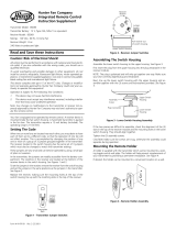
setting up the remote
Transmitter Model: 85095
Transmitter Battery: 12 V, Type 23A, MN-21 or equivalent
Receiver Model: 85069
Ratings: 120 VAC, 60 Hz,1.0 Amp Fan
Receiver Weight: 8 oz.
240 Watts incandescent light
Caution: Risk of Electrical Shock!
All wiring must be performed in accordance with national
and local electrical codes. If you are unfamiliar with the
wiring codes, you should use a qualified electrician.
To avoid overheating and possible damage to other equip-
ment, do not install to control a receptacle, fluorescent
light fixture, motor operated appliance, or transformer-
supplied appliance. Use only to control one paddle-blade
ceiling fan and incandescent light fixture.
This device complies with part 15 of the FCC rules. Changes
or modifications not expressly approved by Hunter Fan
Company could void your authority to operate this equip-
ment!
Operation Is Subject To The Following Two Conditions:
1. This device may not cause harmful interference.
2. This device must accept any interference received, in-
cluding interference that may cause undesired operation.
Note: Any changes or modifications to the transmitter or
receiver not expressly approved by Hunter Fan Company
may void one’s authority to operate this remote control.
Your fan is equipped to be operated by remote control. A receiver
device is mounted inside the fan switch housing. A hand-held trans-
mitter is packed in the fan box. The transmitter requires a 12-volt
battery (included). The operating range is 15-30 feet.
setting the code
When two or more fans are located near each other, you may de-
sire to have each of them set to a different code, so that the opera-
tion of one fan will not affect another. This is accomplished by chang-
ing the position of any one or more of a group of 3 jumpers grouped
together in the transmitter. The receiver located in the switch hous-
ing has the same set of 3 jumpers which must also be changed to
match the transmitter settings.
These jumpers are very small and can best be operated by using a
small pair of pliers or tweezers.
In the transmitter, the jumpers are readily accessible from the bat-
tery compartment. The switches in the receiver are located at the
bottom of the receiver device in the switch housing. See Figures 26
and 27.
To set the jumpers in the receiver, remove the receiver from the
switch housing and set the jumpers in the same positions as the
jumpers in the transmitter. See Figure 27.
Replace the receiver, making sure the mounting holes at the top of
the switch housing line up with the matching slots in the top of the
receiver.
Figure 26 - Transmitter jumper switches
Blade Iron
Medallion
Jumper
Switch
Transmitter Back
41810-01_rev 8-20-04 v 3.pmd 8/21/04, 4:36 PM8

© 2004 Hunter Fan Company 41810-01 08/20/2004
9
Figure 27 - Receiver jumper switches
installing the light fixture
You can install with or without the light fixture. If you want to
install without the light fixture, skip to the installing without the
light fixture section.
WARNING: Use only the supplied light fixture for this fan
model.
attaching the upper switch housing
1. Partially install two #6-32 x 3/8" housing assembly screws into
the switch housing mounting plate as shown in Figure 28.
2. Feed the upper plug connector through the center opening of
the upper switch housing. See Figure 28.
Figure 28 - Attaching the upper
switch housing to the mounting plate
3. Align the keyhole slots in the upper switch housing with the
housing assembly screws installed previously.
4. Turn the upper switch housing counterclockwise until the
housing assembly screws are firmly situated in the narrow end
of the keyhole slots as shown in Figure 29. Install the one re-
maining #6-32 x 3/8" housing assembly screw into the third
hole in the upper switch housing. Tighten all three screws
firmly.
Figure 29 - Mounting the upper switch housing
CAUTION: Make sure the upper switch housing is se-
curely attached to the switch housing mounting plate. Fail-
ure to properly attach and tighten all three housing assem-
bly screws could result in the switch housing and light fix-
ture falling.
attaching the lower switch housing
1. First insert the plug from the upper housing into the plug re-
ceptacle in the receiver module.
NOTE: The plug is polarized and will only go together one
way. Make sure you have correctly aligned plug and receptacle.
Figure 30 - Connecting the plug connectors
2. Place the lower switch housing assembly over the upper switch
housing. Align the side screw holes in the upper and lower
switch housings. Attach the lower switch housing to the up-
per switch housing with three #6-32 x 3/8" housing assembly
screws. See Figure 30.
NOTE: If the two pieces are difficult to assemble, check the
alignment of the (3) slots in the top of the receiver module
and the mounting holes in the lower switch housing. They
should align together.
Receiver Bottom
Jumper
Switch
Lower Switch Housing
Pull receiver
out of switch
housing
Switch Housing
Mounting Plate
Upper Switch
Housing
Housing
Assembly
Screw
Upper Plug
Connector
Assembly Screw
Plug Connector
Upper Switch
Housing
Lower Switch
Housing
41810-01_rev 8-20-04 v 3.pmd 8/21/04, 4:36 PM9

41810-01 08/20/2004 © 2004 Hunter Fan Company
10
installing the glass bowl
Refer to Figure 31.
1. Install two max 60 Watt medium base incandescent bulbs.
2. Remove the cover plate and finial from the threaded rod on
the light fixture.
3. Place the cover plate up against the glass bowl. Align the holes
in the cover plate and glass bowl.
4. Screw the finial onto the threaded rod end until tight.
Figure 31 - Installing the glass bowl
installing without the light fixture
Your Hunter fan comes with an integrated light fixture assembly
and an optional switch housing cap and plug button. This feature
gives you the option of installing the fan with or without the in-
cluded light fixture.
If you decide to install the fan without the integrated light fixture
please complete the following instructions to install the optional
switch housing cap and plug button.
attaching the upper switch housing
1. Partially install two #6-32 x 3/8" housing assembly screws into
the switch housing mounting plate as shown in Figure 28.
2. Feed the upper plug connector through the center opening of
the upper switch housing. See Figure 28.
3. Align the keyhole slots in the upper switch housing with the
housing assembly screws installed previously.
4. Turn the upper switch housing counterclockwise until the
housing assembly screws are firmly situated in the narrow end
of the keyhole slots as shown in Figure 29. Install the one re-
maining #6-32 x 3/8" housing assembly screw into the third hole
in the upper switch housing. Tighten all three screws firmly.
CAUTION: Make sure the upper switch housing is se-
curely attached to the switch housing mounting plate. Fail-
ure to properly attach and tighten all three housing assem-
bly screws could result in the switch housing and light fix-
ture falling.
attaching the lower switch housing
uninstalling the light fixture
Refer to Figure 32.
1. Remove the receiver from the lower switch housing.
2. Disconnect the plug connectors between the black wire and
the black/white wire.
3. Disconnect the plug connectors between the two white wires.
4. Uninstall the nut and washer from the end of the light fixture
inside of the lower switch housing.
5. Unscrew the threaded rod of the light fixture from the lower
switch housing.
6. Remove the light fixture from the lower switch housing pull-
ing disconnected wires through the hole in the center of the
lower switch housing.
NOTE: When removing the wires, pull the thin plug connec-
tor (male) through first, and then pull the other plug connec-
tor (female) through the hole.
7. Install the dummy terminals (included in the sack parts) on
the two disconnected wires in the lower switch housing.
8. Replace the receiver, making sure the mounting holes at the
top of the switch housing line up with the matching slots in
the top of the receiver.
Figure 32 - Removing the light fixture
Lower Switch
Housing
Glass Bowl
Threaded Rod
Cover Plate
Finial
Metal Disk
Lower Switch
Housing
Threaded Rod
41810-01_rev 8-20-04 v 3.pmd 8/21/04, 4:36 PM10

© 2004 Hunter Fan Company 41810-01 08/20/2004
11
installing the switch housing cap and plug button
Install the switch housing cap and plug button to the lower switch
housing as shown in Figure 33.
Figure 33 - Installing the switch
housing cap and plug button
installing the lower switch housing
1. First insert the plug from the upper housing into the plug re-
ceptacle in the receiver module.
NOTE: The plug is polarized and will only go together one
way. Make sure you have correctly aligned plug and receptacle.
2. Place the lower switch housing assembly over the upper switch
housing. Align the side screw holes in the upper and lower
switch housings. Attach the lower switch housing to the up-
per switch housing with three #6-32 x 3/8" housing assembly
screws. See Figure 30.
NOTE: If the two pieces are difficult to assemble, check the
alignment of the (3) slots in the top of the receiver module
and the mounting holes in the lower switch housing. They
should align together.
operating your ceiling fan
1. Turn on electrical power to the fan.
2. Ceiling fans work best by blowing air downward (counterclock-
wise blade rotation) in warm weather to cool the room with a
direct breeze. In winter, having the fan draw air upward (clock-
wise blade rotation) will distribute the warmer air trapped at
the ceiling around the room without causing a draft. Refer to
Figure 34.
Figure 34 - Air flow patterns
operating the remote control
The hand-held transmitter has individual buttons for control of the
light, for controlling the fan speeds, for turning the fan off, and for
reversing. See Figure 35.
Pressing the “LIGHT” button will turn the light on to full bright-
ness. Holding the button will cause the light to dim slowly—re-
lease the button at the desired brightness to hold the selected
brightness level. Pushing the button again will turn the light off.
The fan may be started by pressing the HIGH, MEDIUM, or LOW
speed buttons. For best operation, allow the fan to start on HIGH,
then select the desired speed. Press the fan OFF button to turn the
ceiling fan off. Press the REVERSE button to change the fan’s direc-
tion while the fan is running.
NOTE: Replace 12-volt battery with type 23 A, MN-21 or equiva-
lent.
Figure 35 - Remote operation
mounting the remote holder
A holder is supplied with the transmitter which can be mounted to
a existing toggle switch wall plate. The holder will help prevent mis-
placement of your transmitter by providing a permanent recep-
tacle. See Figure 36.
If desired, the holder can be mounted to a convenient location on
a wall.
Figure 36 - Remote holder assembly
Lower Switch
Housing
Plug Button
Cap
Reverse
Fan High
Fan Medium
Fan Low
Fan Off
Light Key
41810-01_rev 8-20-04 v 3.pmd 8/21/04, 4:36 PM11

41810-01 08/20/2004 © 2004 Hunter Fan Company
12
cleaning your ceiling fan
caring for finishes
For cleaning, a soft brush or lint-free cloth should be used to pre-
vent scratching the finish. A vacuum cleaner brush nozzle can re-
move heavier dust. Surface smudges or an accumulation of dirt
and dust can easily be removed by using a mild detergent and a
slightly dampened cloth. An artistic agent may be used, but never
use abrasive cleaning agents as they will damage the finish.
caring for blades
Wood finish blades should be cleaned with a furniture polishing
cloth. Occasionally, a light coat of furniture polish may be applied
for added protection and beauty. Painted and high-gloss blades
may be cleaned in the same manner as the fan finish.
troubleshooting
Problem: Nothing happens; fan does not move.
1. Turn power on, replace fuse, or reset breaker.
2. Loosen canopy, check all connections according to the
wiring the fan section.
3. Check the plug connection in the switch housing.
4. Remove the shipping bumpers.
Problem: Noisy operation.
1. Tighten the blade bracket screws until snug.
2. Tighten the blade screws until snug.
3. Check to see if the blade is cracked. If so, replace all
the blades.
4. Be sure that the glass is secure.
5. Check and tighten the screws in the switch housing
mounting plate and in the upper and lower switch
housing.
Problem: Excessive wobbling.
1. If your fan wobbles when operating, use the enclosed bal-
ancing kit and instructions to balance the fan.
2. Tighten all blade and/or blade iron screws.
3. Turn power off, support fan very carefully, and check that
the hanger ball is properly seated.
Problem: No functions operate.
1. Replace fuse. Turn ON circuit breaker. Turn ON wall
switch.
2. Set transmitter and receiver to same jumper switch set-
ting.
3. Replace with new, alkaline battery.
Problem: Operates only at close range.
1. Replace with new, alkaline battery.
Problem: Inconsistent operation.
1. Turn OFF wall switch for 5 seconds, then turn back ON.
2. Change jumper switch settings to a different code in both
transmitter and receiver.
Problem: Fan will not reverse.
1. Select a fan speed button to start fan, then press the re-
verse button.
If you need parts or service assistance, please call 888-830-1326 or
visit us at our WEB site at http://www.hunterfan.com.
Hunter Fan Company
2500 Frisco Avenue
Memphis, Tennessee 38114
41810-01_rev 8-20-04 v 3.pmd 8/21/04, 4:36 PM12
/