Emerson CF985LBS User guide
- Category
- Household fans
- Type
- User guide
This manual is also suitable for

Questions, problems, missing parts: Before returning to the store call
Emerson Electric Customer Service - 8 a.m. - 6 p.m., Eastern, Monday-Friday
Part No. F40BP75000000 Form No. BP7500
Revision: 150108 E.T.L. Model No.: CF985
www.emersonfans.com
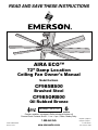
CF985BS00
Brushed Steel
CF985ORB00
Oil Rubbed Bronze
Net Weight: 32.6 Lbs.
READ AND SAVE THESE INSTRUCTIONS
1-800-654-3545
AIRA ECO™
72” Damp Location
Ceiling Fan Owner's Manual
Model Numbers
• Español - página 31
• Français - page 61

2
E.T.L. Model No.: CF985
Safety Instructions
TO REDUCE THE RISK OF FIRE, ELECTRICAL SHOCK,
OR INJURY TO PERSONS, OBSERVE THE FOLLOWING:
a. Use this unit only in a manner intended by the
manufacturer. If you have questions, contact the
manufacturer.
b. Before servicing or cleaning unit, switch power off at
service panel and lock service panel disconnecting
means to prevent power from being switched on
accidentally. When the service disconnecting means
cannot be locked, securely fasten a warning device,
such as a tag, to the service panel.
WARNING
!
Additional Safety Instructions for Installation
1. To avoid possible shock, be sure electricity is turned off
at the fuse box before wiring, and do not operate fan
without blades.
2. All wiring must be in accordance with the National
Electrical Code “ANSI/NFPA 70-2014” and Local
Electrical Codes. Use the National Electrical Code if
Local Codes do not exist. The ceiling fan must be
grounded as a precaution against possible electrical
shock. Electrical installation should be made or
approved by a licensed electrician.
3. The outlet box and joist must be securely mounted and
capable of reliably supporting at least 50 pounds. Use
only U.L. outlet boxes listed as “Acceptable for Fan
Support of 22.7 kg. (50 lbs.) or less”, and use the
mounting screws provided with the outlet box.
Most outlet boxes commonly used for support of light
fixtures are not acceptable for fan support and may need
to be replaced. Consult a qualified electrician if in doubt.
4. The downrod furnished with the fan provides the
minimum recommended floor to fan blade clearance for
an 8 foot ceiling.
5. The fan must be mounted with the fan blades at least
7 feet from the floor to prevent accidental contact with
the fan blades.
6. Follow the recommended instructions for the proper
method of wiring your ceiling fan. If you do not know
enough about electrical wiring, have your fan installed by
a licensed electrician.
WARNING: To reduce the risk of electrical shock, this fan
must be installed with an isolating wall control/switch.
WARNING: To avoid fire, shock or injury, do not use an
Emerson or any other brand of control not specifically
approved for this fan.
WARNING: This product is designed to use only those
parts supplied with this product and/or any accessories
designated specifically for use this product by Emerson
Electric Co. Substitution of parts or accessories not
designated for use with this product by Emerson could
result in personal injury or property damage.
WARNING: To reduce the risk of personal injury, do not
bend the blade flange when installing the blade flanges,
balancing the blades or cleaning the fan. Do not insert
foreign objects in between rotating fan blades.
NOTE: All setscrews must be checked and re-tightened
where necessary before installation.
1. Read your owner’s manual carefully and keep it for future
reference.
2. Be careful of the fan and blades when cleaning, painting,
or working near the fan. Always turn off the power to the
ceiling fan before servicing.
3. Do not put anything into the fan blades while they are
turning.
4. Do not operate reversing switch until fan blades have
come to a complete stop.
DATE CODE:
The date code of this fan may be found on the box, stamped in ink on a white label. You should record
this data above and keep it in a safe place for future use.
READ AND SAVE THESE INSTRUCTIONS
Table of Contents
Section Page
Safety Instructions . . . . . . . . . . . . . . . . . . . . . . . . . . . . . . . . . . . .2
1. Unpacking Instructions . . . . . . . . . . . . . . . . . . . . . . . . . . . . .3-4
2. Electrical Requirements . . . . . . . . . . . . . . . . . . . . . . . . . . . . .4
3. Ceiling Fan Assembly . . . . . . . . . . . . . . . . . . . . . . . . . . . . .5-7
4. How to Hang Your Ceiling Fan . . . . . . . . . . . . . . . . . . . . .8-10
5. How to Wire Your Ceiling Fan . . . . . . . . . . . . . . . . . . . . .10-11
6
. Installation of the Ceiling Cover . . . . . . . . . . . . . . . . . . . . . . .12
7. Installation of the Fan Blades . . . . . . . . . . . . . . . . . . . . . . . . .13
8. Installation of Downlight Assembly . . . . . . . . . . . . . . . . . .14-16
9. Optional Installation of No-Light Cover Plate . . . . . . . . . . . . .17
10. Wall Control Procedures . . . . . . . . . . . . . . . . . . . . . . . . . . . .18
Section Page
11. Wall Control Installation . . . . . . . . . . . . . . . . . . . . . . . . . .19-22
12. Programming Fan Control . . . . . . . . . . . . . . . . . . . . . . . . . .23
13. Using Your Ceiling Fan . . . . . . . . . . . . . . . . . . . . . . . . . . . . .24
14. Maintenance . . . . . . . . . . . . . . . . . . . . . . . . . . . . . . . . . . . . .25
15. Accessories . . . . . . . . . . . . . . . . . . . . . . . . . . . . . . . . . . . . . .25
16. Instruction to the User . . . . . . . . . . . . . . . . . . . . . . . . . . . . . .25
1
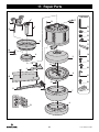
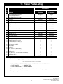
7. Repair Parts . . . . . . . . . . . . . . . . . . . . . . . . . . . . . . . . . .26-27
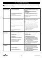
18. Trouble Shooting . . . . . . . . . . . . . . . . . . . . . . . . . . . . . . . . . .28
Ceiling Fan Limited Warranty . . . . . . . . . . . . . . . . . . . . . . . . . .29
Spanish . . . . . . . . . . . . . . . . . . . . . . . . . . . . . . . . . . . . . . . . . . . .31
French . . . . . . . . . . . . . . . . . . . . . . . . . . . . . . . . . . . . . . . . . . . . .61

1. Unpacking Instructions
3
emersonfans.com
Please contact 1-800-654-3545 for further assistance
E.T.L. Model No.: CF985
This product is designed to use only those parts supplied
w
ith this product and/or any accessories designated
specifically for use with this product by Emerson Electric
Co. Substitution of parts or accessories not designated
for use with this product by Emerson Electric Co. could
result in personal injury or property damage.
WARNING
!
Do not install or use fan if any part is damaged or
missing. Call Toll-Free:
1-800-654-3545
WARNING
!
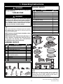
1.1
Open carton containing fan. Remove top half of styrofoam
unit. Remove parts and check to see that you have
received the following parts:
NOTE: If you are uncertain of part description, refer to
exploded view illustration.
NOTE: Place the parts from the loose parts bags in a
small container to keep them from being lost.
If any parts are missing, call 1-800-654-3545
for replacement parts before proceeding.
A
F
G
H
I
J
K
N
M
E
D
C
B
L
PACKAGE CONTENTS
8
7
10
11
9
1
3
2
4
5
6
HARDWARE CONTENTS
Part Description Quantity
1 #8-32 x 8mm Washer Head Screws 41
2 1/4-20 x 1/2” Oval Head Screw 17
3 Wire Connectors, 12 ga. 5
4 Threaded Studs, #8-32 x 1-1/4” 2
5 Knurled Knobs, #8-32 2
6 Lockwashers, External Tooth #8 2
7 #6-32 x 3/8” Truss Head Screw
w/Lockwashers (Spares) 2
8 Clevis Pin 1
9 Hairpin Clip 1
10 Hex Wrench 1
11 Blade Balance Kit 1
1.2
Remove the fan housing assembly from the protective
plastic bag. Turn the upper styrofoam pad over and
carefully place the fan motor assembly into the recess in
the pad with the top of the motor facing up.
Part Description Quantity
A Fan Motor Assembly 1
B Hanger Bracket 1
C Hanger Ball / 6” Downrod Assembly 1
D Ceiling Cover 1
E Coupling Cover 1
F Light Fitter Housing 1
G Light Fitter 1
H Glass Bowl 1
I Removable No-Light Cover Plate 1
J Blade Flanges 8
K Fan Blades 8
L Blade Flange Plates 8
M 50-Watt Mini-Candelabra Base Halogen Bulbs 2
N SW605 Wall Control/Hardware 1

4
E.T.L. Model No.: CF985
The outlet box must be securely anchored and capable of
withstanding a load of at least 50 pounds.
If your fan is to replace an existing ceiling light fixture, turn
electricity off at the main fuse box at this time and remove
the existing light fixture.
Before assembling your ceiling fan, refer to section on
proper method of wiring your fan (page 10). If you feel
you do not have enough wiring knowledge or experience,
have your fan installed by a licensed electrician.
WARNING
!
This Manual Is Designed to Make it as Easy as Possible for You to Assemble,
Install, Operate and Maintain Your Ceiling Fan
Tools Needed for Assembly
One Phillips head screwdriver One stepladder
One 1/4” blade screwdriver One wire stripper
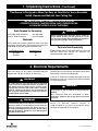
Materials
Wiring outlet box and box connectors must be of type
required by the local code. The minimum wire would be a
3-conductor (2-wire with ground) of following size:
Installed Wire Length Wire Size A.W.G.
Up to 50 ft. 14
50-100 ft. 12
2. Electrical Requirements
Your new ceiling fan will require a grounded electrical
supply line of 120 volts AC, 60 Hz, 15 amp circuit.
To reduce the risk of fire, electric shock, or personal
injury, mount fan to outlet box marked “Acceptable for
Fan Support of 22.7 kg. (50 lbs.) or less”, and use screws
supplied with outlet box. Most outlet boxes commonly
used for support of light fixtures are not acceptable for
fan support and may need to be replaced. Consult a
qualified electrician if in doubt.
WARNING
!
Turning off wall switch is not sufficient. To avoid possible
electrical shock, be sure electricity is turned off at the
main fuse box before wiring. All wiring must be in
accordance with National and Local codes and the ceiling
fan must be properly grounded as a precaution against
possible electrical shock.
WARNING
!
To avoid fire or shock, follow all wiring instructions
carefully.
Any electrical work not described in these
instructions should be done or approved by a licensed
electrician.
WARNING
!
1. Unpacking Instructions (Continued)
Please call Emerson technical support at
1-800-654-3545 if you have any questions about
installation and operation of this ceiling fan.
Controls Sold Separately
SR600 Remote Control (sold separately) may be used
with this AIRA ECO Ceiling Fan. Controls are
recommended for indoor use only.
THIS FAN IS SUITABLE FOR DAMP LOCATIONS SUCH AS
COVERED PORCHES, COVERED PATIOS, AND COVERED DECKS.
ANYWHERE THERE IS A ROOF OVERHEAD.

5
emersonfans.com
Please contact 1-800-654-3545 for further assistance
E.T.L. Model No.: CF985
Turning off wall switch is not sufficient. To avoid possible
e
lectrical shock, be sure electricity is turned off at the
main fuse box before wiring. All wiring must be in
accordance with National and Local codes and the ceiling
fan must be properly grounded as a precaution against
possible electrical shock.
WARNING
!
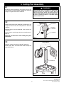
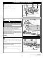
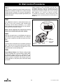
3.1
Disconnect electrical power to the branch circuit at the
circuit breaker or fuse box before attempting to install the
c
eiling fan hanger bracket on the outlet box.
SETSCREW
(LOOSENED)
HANGER BALL
6" DOWNROD
PIN
Figure 1
3. Ceiling Fan Assembly
3.2
Remove the hanger ball by loosening the setscrew in the
hanger ball until the ball falls freely down the downrod
(Figure 1).
Remove the pin from the downrod, then remove the
hanger ball.
Retain the pin and hanger ball for reinstallation in
Step 3.8.
NOTE: Do not loosen the screw holding the green
ground wire.
6" DOWNROD
TWO 80" MOTOR
LEADS (UNTWISTED)
Figure 2
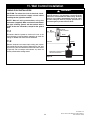
3.3
Separate, untwist and unkink the two 80” motor leads.
Route the 80” black and white motor leads through the
downrod (Figure 2).

6
E.T.L. Model No.: CF985
6" DOWNROD
CLEVIS
P
IN
H
AIRPIN
CLIP
MOTOR
COUPLING
HAIRPIN
CLIP
CLEVIS
PIN
LOOSEN
S
ETSCREWS (2)
M
OTOR
COUPLING
Figure 3
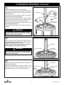
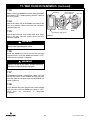
3. Ceiling Fan Assembly (Continued)
3.4
Loosen the two setscrews in the motor coupling.
Place the 6” downrod into the motor coupling, aligning the
c
levis pin holes in the downrod with the holes in the motor
coupling (Figure 3).
The clevis pin must go through the holes in the motor
coupling and the holes in the downrod.
Be sure to push the straight leg of the hairpin clip through
the hole near the end of the clevis pin until the curved
portion of the hairpin clip snaps around the clevis pin.
The hairpin clip must be properly installed to prevent the
clevis pin from working loose.
Pull on the downrod to make sure the clevis pin is properly
installed.
6" DOWNROD
RETIGHTEN
SETSCREWS (2)
MOTOR COUPLING
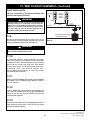
3.5
While pulling up on the 6” downrod, retighten the two
setscrews (previously loosened) in the motor coupling to
secure the downrod into place (Figure 4).
NOTE: The setscrews must be properly installed as
described above, or fan wobble could result.
6" DOWNROD
MOTOR
HOUSING
COUPLING COVER
COUPLING COVER
GROMMET
Figure 5
3.6
Route the 80” black and white motor leads through the
coupling cover (Figure 5).
Make sure the grommet is properly installed in the
coupling cover then slide the coupling cover on the
downrod until it rests on the motor housing (Figure 5).
It is critical that the clevis pin in the motor coupling is
properly installed. Failure to verify that the pin is properly
installed could result in the fan falling.
WARNING
!
It is critical that the setscrews are securely tightened.
Failure to verify that the setscrews are properly installed
could result in the fan falling.
WARNING
!
Figure 4

7
emersonfans.com
Please contact 1-800-654-3545 for further assistance
E.T.L. Model No.: CF985
CEILING
COVER
6" DOWNROD
Figure 6
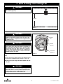
3. Ceiling Fan Assembly (Continued)
3.7
Route the 80” black and white motor leads through the
ceiling cover (Figure 6).
Place the ceiling cover over the downrod. Be sure both the
ceiling cover and the coupling cover are oriented correctly
(Figure 6).
HANGER
BALL
SETSCREW
PIN
6" DOWNROD
Figure 7
3.8
NOTE: Only use the hanger ball supplied with this
ceiling fan.
Route the two 80” motor leads through the hanger ball.
Reinstall the hanger ball (Figure 7) on the downrod as
follows:
Position the hanger ball pin through the two holes in the
downrod and align the ball so the pin is captured in the
groove in the top of the hanger ball.
Pull the hanger ball up tight against the pin and securely
tighten the setscrew in the hanger ball.
NOTE: A loose setscrew could create fan wobble.
HANGER BALL/
DOWNROD
ASSEMBLY
6 to 9
INCHES
Figure 8
3.9
The fan comes with black and white leads that are
80-inches long.
Before installing the fan, measure up approximately
6 to 9-inches above top of hanger ball/downrod assembly
(Figure 8).
Cut off excess leads and strip back insulation 1/2-inch
from end of leads.

8
E.T.L. Model No.: CF985
The outlet box and joist must be securely mounted and
capable of supporting at least 50 lbs. Use only a U.L.
outlet box listed as “Acceptable for Fan Support of 22.7
kg. (50 lbs.) or less”.
WARNING
!
The fan must be hung with at least 7' of clearance from
floor to blades (Figure 9).
WARNING
!
To reduce the risk of fire, electric shock, or personal
injury, mount fan to outlet box marked “Acceptable for
Fan Support of 22.7 kg. (50 lbs.) or less”, and use screws
supplied with outlet box. Most outlet boxes commonly
used for support of light fixtures are not acceptable for
fan support and may need to be replaced. Consult a
qualified electrician if in doubt.
WARNING
!
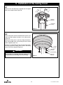
4. How to Hang Your Ceiling Fan
FLOOR
AT LEAST
7'
CEILING
Figure 9
OUTLET BOX
SCREWS (2)
HANGER
BRACKET
OUTLET
BOX
4.1
Securely attach the hanger bracket to the outlet box using
the two screws supplied with the outlet box. (Figure 10).
NOTE: Use only the hanger bracket supplied with this
ceiling fan.
Figure 10
Hanger bracket must seat firmly against outlet box.
If the outlet box is recessed, remove wall board until
bracket contacts box. If bracket and/or outlet box are not
securely attached, the fan could wobble or fall.
WARNING
!

9
emersonfans.com
Please contact 1-800-654-3545 for further assistance
E.T.L. Model No.: CF985
4. How to Hang Your Ceiling Fan (Continued)
To avoid possible fire or shock, do not pinch wires
between the hanger ball/downrod assembly and hanger
bracket.
WARNING
!
Failure to seat tab in groove could cause damage to
electrical wires and possible shock or fire hazard.
WARNING
!
HANGER
BRACKET
ANTI-ROTATION
TAB
HANGER BALL/
DOWNROD
ASSEMBLY
HANGER BRACKET
HANGER BALL
HANGER BALL
GROOVE
ANTI-ROTATION
TAB
Figure 12
4.3
Carefully lift the partially assembled ceiling fan and seat
the hanger ball / downrod assembly on the hanger bracket
(Figure 12).
Be sure the groove in the ball is engaged with the anti-
rotation tab on the hanger bracket (Figure 12).
H
ANGER
B
RACKET
OUTLET
BOX
RETAINING
STRAP
SOCKET CAP SCREW
HEX WRENCH
Figure 11
4.2
Remove the socket head cap screw with the hex wrench
(
supplied in the parts bag) from the retaining strap to the
hanger bracket (Figure 11); retain the socket head cap
screw for future use.
Swing open the retaining strap as shown in Figure 11.

10
E.T.L. Model No.: CF985
4. How to Hang Your Ceiling Fan (Continued)
SOCKET CAP SCREW
HEX WRENCH
R
ETAINING STRAP
HANGER BRACKET
Figure 13
4.4
Rotate the retaining strap closed (Figure 13) on the
h
anger bracket.
R
einstall the socket head cap screw (previously removed).
Securely tighten the socket head cap screw (Figure 13).
If you feel that you do not have enough electrical
wiring knowledge or experience, have your fan
installed by a licensed electrician.
5.1
Connect the green grounding lead from the hanger ball
and the green grounding lead from the hanger bracket to
the grounding conductor of supply (this may be a bare
wire or wire with green colored insulation). Securely
connect wires with wire connectors supplied (Figure 14).
5. How to Wire Your Ceiling Fan
To avoid possible electrical shock, be sure electricity is
turned off at the main fuse box before wiring.
NOTE: If you are not sure if the outlet box is grounded,
contact a licensed electrician for advice, as it must be
grounded for safe operation.
WARNING
!
This product is designed to use only those parts supplied
with this product and/or any accessories designated
specifically for use with this product by Emerson Electric
Co. Substitution of parts or accessories not designated
for use with this product by Emerson Electric Co. could
result in personal injury or property damage.
WARNING
!
GROUND
CONDUCTOR SUPPLY
LISTED WIRE
CONNECTOR
GREEN WIRE
(GROUND) FROM
HANGER BRACKET
GREEN WIRE
(GROUND) FROM
HANGER BALL
Figure 14
Turning off wall switch is not sufficient. To avoid possible
electrical shock, be sure electricity is turned off at the
main fuse box before wiring. All wiring must be in
accordance with National and Local codes and the ceiling
fan must be properly grounded as a precaution against
possible electrical shock.
WARNING
!

11
emersonfans.com
Please contact 1-800-654-3545 for further assistance
E.T.L. Model No.: CF985
LISTED WIRE
CONNECTOR
SUPPLY WHITE
(NEUTRAL)
F
AN MOTOR
W
HITE WIRE
Figure 15
5.2
Securely connect the fan motor white wire to the supply
white (neutral) wire using wire connector supplied
(Figure 15).
5. How to Wire Your Ceiling Fan (Continued)
FAN MOTOR
BLACK WIRE
SUPPLY
BLACK
(HOT)
LISTED WIRE
CONNECTOR
Figure 16
5.3
Securely connect the fan motor black wire to the supply
black (hot) wire using wire connector supplied
(Figure 16).
BLACK WIRES
WHITE WIRES
GREEN
WIRES
Figure 17
5.4
After connections have been made, turn leads upward
and carefully push leads into the outlet box, with the white
and green leads on one side of the outlet box and position
the black leads on the other side of the outlet box
(Figure 17).
Check to see that all connections are tight, including
ground, and that no bare wire is visible at the wire
connectors, except for the ground wire. Do not
operate fan until blades are in place. Noise and fan
damage could result.
WARNING
!

12
E.T.L. Model No.: CF985
To avoid possible fire or shock, make sure that the
electrical wires are completely inside the outlet box and
not pinched between the ceiling cover and the ceiling.
WARNING
!
6. Installation of the Ceiling Cover
THREADED
STUD (2)
HANGER
B
RACKET
Figure 18
6.1
Screw the two threaded studs (supplied) into the tapped
h
oles in the hanger bracket (Figure 18)
THREADED
STUD (2)
LOCKWASHER (2)
KNURLED
KNOB (2)
CEILING
COVER
Figure 19
6.2
Lift the ceiling cover up to the threaded studs and turn until
studs protrude through the holes in the ceiling cover
(Figure 19).
Secure the ceiling cover in place by sliding lockwashers
over the threaded studs and installing the two knurled
knobs (supplied) (Figure 19).
Tighten the knurled knobs securely until the ceiling cover
fits snugly against the ceiling and the hole in the ceiling
cover is clear of the downrod (Figure 19).

13
emersonfans.com
Please contact 1-800-654-3545 for further assistance
E.T.L. Model No.: CF985
7. Installation of the Fan Blades
BLADE FLANGE PLATE
#8-32 x 8mm WASHER
HEAD BLADE SCREW (5)
CEILING FAN BLADE
C
URVED PORTION
OF FAN BLADE
FACING
DOWNWARD
BLADE FLANGE
Figure 21
7.2
Position a ceiling fan blade (with the curved portion of the
blade facing down) onto a blade flange (Figure 21).
Place a blade flange plate onto the the ceiling fan blade,
aligning the five holes (Figure 21).
Securely fasten the blade flange, ceiling fan blade and the
blade flange plate using five #8-32 x 8mm washer head
blade screws per blade (Figure 21).
Repeat for remaining seven blade/flange/plate
assemblies.
1/4-20 x 1/2" OVAL HEAD SCREW
(2 per blade/flange assembly)
MOTOR HUB
FLANGE/BLADE
ASSEMBLY
FLANGE NTERCONNECT NG L
Figure 22
7.3
Attach the flange/blade assembly to the motor hub using
two 1/4-20 x 1/2” oval head screws (supplied)
(Figure 22).
Attach the flange/blade assemblies clockwise making sure
that the interconnecting lip of the flanges mate with the
next flange attachment (Figure 22).
Repeat this procedure for the other seven flange/blade
assemblies.
Make sure all the screws are tightened securely.
To reduce the risk of personal injury, do not bend the
blade flanges when installing the flanges, balancing the
blades, or cleaning the fan. Do not insert foreign objects
between rotating fan blades.
WARNING
!
SHIPPING SPACER (4)
SHIPPING SPACER SCREW (4)
MOTOR
ASSEMBLY
Figure 20
7.1
Remove the shipping spacers and the spacer attachment
s
crews from the motor before installation of blade
assemblies (Figure 20).
Discard the spacers and spacer screws.

14
E.T.L. Model No.: CF985
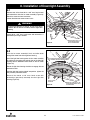
8. Installation of Downlight Assembly
8.2
Pass the fan motor assembly’s black and white leads
through the center hole of the light fitter housing.
Install the light fitter housing onto the fan motor assembly
by aligning and engaging the keyhole slots of the light fitter
housing with the loosened screw heads on the fan motor
(Figure 24).
Rotate the light fitter housing clockwise to engage the two
loosened screws.
With the light fitter housing locked into position, tighten the
two previously loosened screws.
Reinstall the #6-32 x 3/8” truss head screw with
lockwasher (previously removed) into the light fitter
housing (Figure 24).
REINSTALL ONE #6-32 x 3/8"
TRUSS HEAD SCREW WITH
LOCKWASHER
LIGHT FITTER
HOUSING
ROTATE LIGHT FITTER HOUSING CLOCKWISE
TO ENGAGE THE TWO LOOSENED SCREWS
Figure 24
T
o avoid possible fire or shock, do not pinch wires
between the fan motor assembly and the light fitter
housing.
WARNING
!
8.1
Remove one of the three #6-32 x 3/8” truss head screws
with lockwashers from the fan motor assembly (Figure 23).
R
etain the screw for future installation.
Loosen the other two screws several turns.
REMOVE ONE #6-32 x 3/8"
TRUSS HEAD SCREW
WITH LOCKWASHER
FAN MOTOR
ASSEMBLY
Figure 23
Spare #6-32 x 3/8” truss head screw with lockwasher is
provided in parts bag if needed.

15
emersonfans.com
Please contact 1-800-654-3545 for further assistance
E.T.L. Model No.: CF985
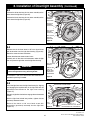
8. Installation of Downlight Assembly (Continued)
8.5
Install the light fitter onto the light fitter housing by aligning
and engaging the keyhole slots of the light fitter with the
loosened screw heads on the light fitter housing
(Figure 27).
Rotate the light fitter clockwise to engage the two loosened
screws.
With the light fitter locked into position, tighten the two
previously loosened screws.
Reinstall the #6-32 x 3/8” truss head screw with
lockwasher (previously removed) into the light fitter
(Figure 27).
LIGHT
FITTER
ROTATE LIGHT FITTER CLOCKWISE TO
ENGAGE THE TWO LOOSENED SCREWS
REINSTALL ONE #6-32 x 3/8” TRUSS
HEAD SCREW WITH LOCKWASHER
Figure 27
8.3
Connect the white wire from the fan motor assembly to the
white wire of the light fitter (Figure 25).
Connect the black wire from the fan motor assembly to the
black wire of the light fitter (Figure 25).
LIGHT FITTER
HOUSING
WHITE WIRE
LIGHT FITTER
H
OUSING
BLACK WIRE
FAN MOTOR
ASSEMBLY
BLACK WIRE
FAN MOTOR
A
SSEMBLY
WHITE WIRE
Figure 25
To avoid possible fire or shock, do not pinch wires
between the light fitter housing and the light fitter.
WARNING
!
8.4
Remove one of the three #6-32 x 3/8” truss head screw
with lockwasher from the light fitter housing (Figure 26).
Retain the screw for future installation.
Loosen the other two screws several turns.
Carefully tuck all the wires and connectors under the light
fitter and place the light fitter onto the light fitter housing.
REMOVE ONE
#6-32 x 3/8"
TRUSS HEAD
SCREW WITH
LOCKWASHER
LIGHT FITTER
HOUSING
Figure 26
Spare #6-32 x 3/8” truss head screw with lockwasher is
provided in parts bag if needed.

16
E.T.L. Model No.: CF985
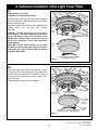
8. Installation of Downlight Assembly (Continued)
8.7
Place the light fitter glass bowl into the light fitter, aligning
the three flat areas on the top flange of the glass bowl with
the three raised studs in the light fitter.
Then turn the glass bowl clockwise until it stops and is
secure (Figure 29).
NOTE: Periodically check that the glass bowl is seated
fully clockwise in the light fitter.
Installation of your ceiling fan is now complete. Proceed
with installation of the wall control.
Proceed to Section 10 to install the wall control.
50-WATT (max.)
MINI-CANDELABRA BASE
HALOGEN BULBS (2)
LIGHT FITTER
SOCKETS (2)
LIGHT
FITTER
Figure 28
If using the No-light Cover Plate, skip this section and
g
o to Section 9.
8.6
Light Fitter Light Bulb Installation:
If light fitter is to be used as a down light, screw in two
50-watt (maximum) mini-candelabra base halogen bulbs
(supplied) into the light fitter sockets (Figure 28).
CAUTION: To avoid risk of burns or other injury,
assure power is off before attempting to install or
replace the 50-watt (max.) mini-candelabra base
halogen bulbs. Halogen bulbs are very hot and can
cause burns. Allow the bulbs to cool sufficiently
before handling.
CAUTION: Do not touch 50-watt (max.) mini-
candelabra base halogen bulbs with bare hands.
Fingerprints may result in shorter bulb life. Remove
fingerprints with alcohol.
LIGHT FITTER
RAISED STUDS (3)
ROTATE GLASS BOWL CLOCKWISE TO
ENGAGE ON THE LIGHT FITTER RAISED STUDS
LIFT GLASS BOWL UP
INTO LIGHT FITTER
FLAT AREA
OF GLASS
BOWL (3)
GLASS
BOWL
Figure 29

17
emersonfans.com
Please contact 1-800-654-3545 for further assistance
E.T.L. Model No.: CF985
9. Optional Installation of No-Light Cover Plate
9.1
If NO light fitter is to be used,
Installation of the No-Light Cover Plate:
Remove the glass bowl from the light fitter by turning the
bowl counter-clockwise. Store glass bowl in a secure place
for future use (Figure 30).
Remove the two 50-watt (maximum) mini-candelabra base
halogen bulbs from the light fitter sockets
(Figure 30).
CAUTION: To avoid risk of burns or other injury,
assure power is off before attempting to install or
replace the 50-watt (max.) mini-candelabra base
halogen bulbs. Halogen bulbs are very hot and can
cause burns. Allow the bulbs to cool sufficiently
before handling.
CAUTION: Do not touch 50-watt (max.) mini-
candelabra base halogen bulbs with bare hands.
Fingerprints may result in shorter bulb life. Remove
fingerprints with alcohol.
REMOVE 50-WATT (max.) MINI-
CANDELABRA BASE HALOGEN
BULBS (2)
ROTATE GLASS BOWL COUNTER-CLOCKWISE
TO REMOVE FROM LIGHT FITTER
GLASS
BOWL
LIGHT
F
ITTER
Figure 30
9.2
Place the no-light cover plate into the light fitter, aligning
the three flat areas on the top flange of the no-light cover
plate with the three raised studs in the light fitter. Then turn
the no-light cover plate clockwise until it stops and is
secure (Figure 31).
Proceed to Section 10 to install the wall control.
NO-LIGHT
COVER
PLATE
ROTATE NO-LIGHT COVER PLATE CLOCKWISE TO
ENGAGE ON THE LIGHT FITTER RAISED STUDS
LIFT NO-LIGHT COVER PLATE
UP INTO LIGHT FITTER
FLAT AREA
OF NO-LIGHT
COVER
PLATE (3)
LIGHT FITTER
RAISED STUDS (3)
Figure 31

18
E.T.L. Model No.: CF985
10. Wall Control Procedures
10.1
Your Emerson Ceiling Fan/Light Control consists of
SW605 wall mounted transmitter and a receiver located
inside the motor assembly. The control is designed to
remotely operate your ceiling fan speed, light intensity and
d
irection of rotation.
Code switches in the transmitter may be set in
32 different positions. If your fan and light turn on and
off without using your control, you may be getting
i
nterference from other remote units such as garage
door openers, car alarms or security systems.
To remedy this situations, simply change the code
switches in your transmitter per the instructions of
Section 12.
10.2
Your SW605 wall control has code switches which must
be set in one of 32 possible code combinations
(Figure 32). The five levers (numbered 1, 2, 3, 4, and 5)
on the switches are factory-set in the ON (up) position.
Change the switch settings as follows:
NOTE: Do not duplicate the code of an existing
control of an installed ceiling fan within 100 feet.
10.3
Slide the five switch levers in the SW605 wall control to
your choice of ON (up) or down positions. Use a ball-point
pen or small screwdriver and slide the levers firmly up or
down.
10.4
The sixth switch marked ON and I is for dimming control of
lights: Set switch to ON to allow for dimming of the lights.
Set switch to I for no dimming of the lights such as for
fluorescent bulbs and non-dimming CFLs.
10.5
Preset Memory Feature: Your Emerson ceiling fan/light
control is equipped with a preset memory feature. When
the electricity supply to the fan is switched OFF, the
control will remember the light intensity and fan speed.
When the switch is turned back ON, the light and fan will
resume operation as they were prior to the switch being
turned OFF.
SW605 WALL CONTROL
CODE SWITCHES
ON
1
2 3
4
5 I
CODE
SWITCHES
SW605 WALL
CONTROL
Figure 32

19
emersonfans.com
Please contact 1-800-654-3545 for further assistance
E.T.L. Model No.: CF985
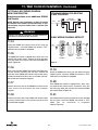
11. Wall Control Installation
SINGLE-POLE INSTALLATION
EXISTING
WALL CONTROL
HOT
BLK
NEUTRAL
BLACK
GROUND
LOAD
BLACK
RECEIVER LOCATED WITHIN
THE MOTOR HOUSING
Figure 33
Turning off wall switch is not sufficient. To avoid possible
electrical shock, be sure electricity is turned off at the
main fuse or circuit breaker box before wiring. All wiring
must be in accordance with National and Local codes
and the ceiling fan must be properly grounded as a
precaution against possible electrical shock.
WARNING
!
C
AUTION: To reduce the risk of electrical shock,
disconnect the electrical supply circuit before
installing the fan, light kit or receiver.
N
OTE: Make all wiring connections using wire
connectors (supplied). Make sure that all connections
are tight, including ground, and that no bare wire is
visible at the wire connectors, except for the ground
wire.
11.1
Disconnect electrical power to the branch circuit at the
circuit breaker or fuse box before attempting to install the
ceiling fan SW605 wall control into the outlet box.
11.2
Remove faceplate and screws from existing wall control.
Pull control out from the wall box. Determine the “hot” wire
and the “load” wire and disconnect these wires from control
(Figure 33). Do not attempt to disconnect any wires not
already connected to existing control.

20
E.T.L. Model No.: CF985
11. Wall Control Installation (Continued)
11.3
Before installing the SW605 wall control, place the SW605
wall control in “OFF” mode by pushing “ON/OFF” switch to
the “OFF” position.
11.4
Connect one black wire of the SW605 wall control to the
“hot” wire. Securely connect wires with wire connectors
supplied (Figure 34).
11.5
Connect one black wire of wall switch to the “load” (black)
wire in wall box. Securely connect wires with wire
connector supplied.
11.6
Screw the SW605 wall control into wall box using the
supplied screws. Leave the SW605 wall control in “OFF”
mode until fan installation is completed.
11.7
The SW605 wall control is supplied with a white, ivory, and
almond color switch covers. Choose the finish that best
suits your needs and snap the cover onto the SW605 wall
control (Figure 34).
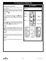
11.8
Install decorator wall plate using the two screws provided
with wall plate. Leave the SW605 wall control in “OFF”
mode until fan installation is completed
(Figure 34).
SW605 FAN/LIGHT
WALL CONTROL
WALL BOX
B
L
A
C
K
B
L
K
H
O
T
SWITCH COVER
DECORATIVE WALL PLATE
S
CREWS (2)
NEUTRAL
WIRES
T
O
1
2
0
V
A
C
S
O
U
R
C
E
T
O
L
O
A
D
G
R
O
U
N
D
Figure 34
Check to see that all connections are tight and that no
bare wires are visible at the wire connectors.
WARNING
!
Do not connect any neutral (white) wire to this control.
Incorrect wiring will damage this control.
WARNING
!
Page is loading ...
Page is loading ...
Page is loading ...
Page is loading ...
Page is loading ...
Page is loading ...
Page is loading ...
Page is loading ...
Page is loading ...
Page is loading ...
-
 1
1
-
 2
2
-
 3
3
-
 4
4
-
 5
5
-
 6
6
-
 7
7
-
 8
8
-
 9
9
-
 10
10
-
 11
11
-
 12
12
-
 13
13
-
 14
14
-
 15
15
-
 16
16
-
 17
17
-
 18
18
-
 19
19
-
 20
20
-
 21
21
-
 22
22
-
 23
23
-
 24
24
-
 25
25
-
 26
26
-
 27
27
-
 28
28
-
 29
29
-
 30
30


Emerson CF985LBS User guide
- Category
- Household fans
- Type
- User guide
- This manual is also suitable for
Ask a question and I''ll find the answer in the document
Finding information in a document is now easier with AI
Related papers
-
Emerson CF755PW04 User manual
-
-
-
Emerson CF990BS00 User manual
-
-
-
-
-
-
Other documents
-
Crystorama LEN-252-CH Operating instructions
-
-
-
-
 Generation Lighting VS29003-BS Installation guide
-
Design House 154195 Installation guide
-
Parrot Uncle BBCF717ORB Installation guide
-
Illumine CLI-EMM023804 Installation guide
-
Illumine CLI-EMM029271 Operating instructions
-
