Page is loading ...

STAINLESS STEEL, WATERBASE COMPATIBLE
Fluid Pressure Regulators
Used to regulate fluid pressure in low pressure systems only.
Fluid Flow up to 3 GPM (11 liters/min)
Instructions–Parts List
307212ZAC
EN
Important Safety Instructions
Read all warnings and instructions in this manual.
Save these instructions.
See page 2 for Table of Contents. See page 3 for
List of Models.

2 307212
Table of Contents
Models 3. . . . . . . . . . . . . . . . . . . . . . . . . . . . . . . . . . . . . . . .
Warnings 5. . . . . . . . . . . . . . . . . . . . . . . . . . . . . . . . . . . . . .
Installation 6. . . . . . . . . . . . . . . . . . . . . . . . . . . . . . . . . . . . .
Operation 8. . . . . . . . . . . . . . . . . . . . . . . . . . . . . . . . . . . . .
Troubleshooting 11. . . . . . . . . . . . . . . . . . . . . . . . . . . . . . .
Service 12. . . . . . . . . . . . . . . . . . . . . . . . . . . . . . . . . . . . . .
Parts 16. . . . . . . . . . . . . . . . . . . . . . . . . . . . . . . . . . . . . . . .
Dimensions 21. . . . . . . . . . . . . . . . . . . . . . . . . . . . . . . . . . .
Technical Data 22. . . . . . . . . . . . . . . . . . . . . . . . . . . . . . . .
Performance Charts 23. . . . . . . . . . . . . . . . . . . . . . . . . . .
Warranty 24. . . . . . . . . . . . . . . . . . . . . . . . . . . . . . . . . . . . .
Graco Information 24. . . . . . . . . . . . . . . . . . . . . . . . . . . . .

3307212
Models
Spring Operated Fluid Regulators
Part No. Series Maximum Fluid Inlet
Pressure, psi (kPa, bar)
Regulated Pressure
Range, psi (kPa, bar)
Gauge Gauge Pressure
Range,
psi (kPa, bar)
214895 H 250 (1800, 18) 5–100 (34–700, 0.3–7) No n/a
214706 H 250 (1800, 18) 5–100 (34–700, 0.3–7) Yes (see 0–100 (0–700, 0–7)
below)
24A082 A 250 (1800, 18) 5–100 (34–700, 0.3–7) Yes (see 0–100 (0–700, 0–7)
below)
255374 B 250 (1800, 18) 5–100 (34–700, 0.3–7) Yes (see 0–200 (0–1400, 0–14)
below)
217314 F 250 (1800, 18) 20–160 (140–1100, 1.4–11) Yes 0–300 (0–2100, 0–21)
221118 E 250 (1800, 18) 20–160 (140–1100, 1.4–11) No n/a
ISO pitch thread inlet and outlet. Not compatible with US standard pitch.
Fluid housing coated with PTFE polymer.
These models are and certified.
The fluid supply system’s main line pressures often exceed the pressure range of the gauge supplied
with regulators 214706, 255374, and 24A082. Exposing this gauge to excessive pressure can damage
the gauge, causing inaccurate readings and the needle will not return to zero.
This damage is not covered by the Graco warranty.
Air Operated Fluid Regulators
Part No. Series Maximum
Regulated
Air Pressure,
psi (kPa, bar)
Maximum Fluid
Inlet Pressure,
psi (kPa, bar)
Regulated Pressure
Range,
psi (kPa, bar)
Gauge Gauge Pressure
Range,
psi (kPa, bar)
214980 F 30 (210, 2.1) 250 (1800, 18) 0–30 (0–210, 0–2.1) Yes 0–30 (0–210, 0–2.1)
244375 B 100 (700, 7) 250 (1800, 18) 5–100 (34–700, 0.3–7) No n/a
Regulated air pressures from 30–100 psi (210–690 kPa, 2.1–6.9 bar) may be used if a 100 psi rated gauge is
installed.

4 307212
Notes

5307212
WARNING
PRESSURIZED EQUIPMENT HAZARD
Spray from the gun, hose leaks, or ruptured components can splash fluid in the eyes or on the skin
and cause serious injury.
Do not stop or deflect fluid leaks with your hand, body, glove, or rag.
Follow the Pressure Relief Procedure on page 8 whenever you: are instructed to relieve the
pressure; stop spraying; clean, check, or service the equipment; and install or clean the fluid
nozzle.
Tighten all the fluid connections before operating the equipment.
Check the hoses, tubes, and couplings daily. Replace worn, damaged, or loose parts immediately.
Permanently coupled hoses cannot be repaired; replace the entire hose.
INSTRUCTIONS
EQUIPMENT MISUSE HAZARD
Equipment misuse can cause the equipment to rupture, malfunction, or start unexpectedly and result
in a serious injury.
This equipment is for professional use only.
Read all the instruction manuals, tags, and labels before operating the equipment.
Use the equipment only for its intended purpose. If you are uncertain about usage, call your Graco
distributor.
Do not alter or modify this equipment. Use only genuine Graco parts and accessories.
Check the equipment daily. Repair or replace worn or damaged parts immediately.
Do not exceed the maximum working pressure of the lowest rated system component.
Use fluids that are compatible with the equipment wetted parts. See the Technical Data section of
all the equipment manuals. Read the fluid manufacturer’s warnings.
Never use 1,1,1–trichloroethane, methylene chloride, other halogenated hydrocarbon solvents, or
fluids containing such solvents in these regulators. In the event that there is a diaphragm failure, a
serious chemical reaction could occur, with the possibility of explosion.
Route the hoses away from traffic areas, sharp edges, moving parts, and hot surfaces. Do not
expose Graco hoses to temperatures above 180F (82C) or below –40F (–40C).
Never kink or over bend the hoses or use the hoses to pull equipment.
Comply with all applicable local, state, and national fire, electrical, and other safety
regulations.

6 307212
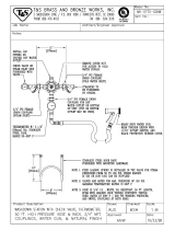
Installation
FLUID SUPPLY
INLET BALL VALVE
OUTLET BALL VALVE
PIPE NIPPLES
BACK
PRESSURE
VALVE
FLUID RETURN
AIR FILTER
& REGULATOR
Spring Operated Installation
Models 214895, 214706, 217314,
221118, 255374, and 24A082
Pilot Regulator Air Supply Line
Air Operated Installation
Model 214980 shown
OUTLET BALL VALVE
AIR SUPPLY
AIR FILTER
MOISTURE SEPARATOR
& REGULATORS
INLET BALL VALVE
Fig. 1
Fig. 2
AIR REGULATOR
BYPASS VALVE
FLUID REGULATOR

7307212
Installation
Fluid pressure regulators are used for accurate, posi-
tive control of the fluid pressure to spray guns, dis-
pensing valves or atomizing heads.
Regulators installed at circulating line take-offs or
pumps are used to reduce main line pressure and
maintain the desired fluid pressure to the spray gun or
atomizing head.
Before Installing the Fluid Regulator
1. Determine where to locate the regulator.
2. Install a ball valve for the regulator inlet and outlet.
3. Install temporary plumbing between the ball
valves.
4. Thoroughly flush the system to remove metal
chips and other contaminants and to check for
leaks.
Installing the Fluid Regulator
1. Remove the temporary plumbing and install one
regulator for each spray gun. See the Dimension-
al Drawing on page 21 for regulator dimensions.
Mount the regulator in a vertical position, as shown
in Figs. 1 and 2, for the best flow and minimum
pigment settling. The gauge, if used, must be
mounted vertically. If the regulator is mounted
horizontally, an elbow must be used so the gauge
will be vertical.
2. Put sealer on threaded connections, except on the
swiveling end of swivel unions as it interferes with
the swivel action.
3. Flush and test the entire system. Be sure to follow
the flushing procedure on page 8.

8 307212
Operation
CAUTION
The new system must be cleaned and tested
thoroughly before admitting fluid to the regulator
to avoid contaminants clogging or damaging the
regulator.
Always use the lowest possible air and fluid
pressures for your application. High pressures
cause premature spray nozzle and pump wear.
NOTE: Reference numbers and letters in parentheses
in the text refer to the Figs. and Parts Drawing.
Pressure Relief Procedure
WARNING
PRESSURIZED EQUIPMENT HAZARD
Read warnings, page 5.
1. Shut off the pump.
2. Close the fluid regulator’s inlet ball valve. Refer to
Figs. 1 and 2.
3. Relieve fluid pressure in the fluid regulator by
triggering the spray gun.
Flushing Procedure
Flush before changing colors, before fluid can dry in
the equipment, at the end of the day, before storing,
and before repairing equipment.
Flush at the lowest pressure possible. Check
connectors for leaks and tighten as necessary.
Flush with a fluid that is compatible with the fluid
being dispensed and the equipment wetted parts.
1. Record the pressure adjustment setting of the fluid
regulator before flushing.
2. Shut off the pump and relieve fluid pressure in the
system by triggering the gun and opening the back
pressure regulator or other bypass valve.
3. Never exceed the maximum working pressure of
the lowest rated system component. Remove the
gauge if the flushing pressure will exceed the
gauge range.
4. Open the fluid regulator fully.
a. Spring Operated Regulators Only (see Fig. 3).
The regulator can be fully opened in two ways:
Using the male end (B) of the regulator
key (24), turn the socket–head adjustment
screw (19) fully counterclockwise. The
pressure setting will be retained.
Using the female end (A) of the regulator
key (24), turn the adjustment screw (12)
fully clockwise. You will have to reset
pressure after flushing.
b. Air Operated Regulator Only. The regulator
can be fully opened in two ways:
Close the outlet valve at the air regulator
and open the air regulator bypass valve, to
supply air directly to the fluid regulator; do
not exceed the maximum rated air pres-
sure of the fluid regulator. Pressure setting
of the fluid regulator will be retained using
this method.
Increase the air regulator setting to fully
open the fluid regulator. You will have to
reset the fluid regulator’s pressure setting
after flushing.
5. Supply solvent to the system. Set pump to the
lowest possible pressure, and start pump.
6. Flush until thoroughly clean.

9307212
Operation
7. Adjust the fluid regulator to the desired setting.
a. Spring Operated Regulators Only (see Fig. 3).
The regulator can be adjusted in two ways:
Using the male end (B) of the regulator
key (24), turn the socket–head adjustment
screw (19) fully clockwise. Verify that the
pressure setting has not changed.
Using the female end (A) of the regulator
key (24), turn the adjustment screw (12)
counterclockwise to return to the desired
pressure setting.
b. Air Operated Regulator Only. The regulator
can be adjusted in two ways:
Close the air regulator bypass valve and
open the outlet valve at the air regulator.
Verify that the pressure setting has not
changed.
Adjust the air regulator to return to the
desired fluid pressure setting.
Regulating Fluid Pressure
Spring Operated Regulator
1. Close the regulator: engage the female end (A) of
the key (24) with the adjusting screw (12) and turn
it counterclockwise to relieve the spring tension.
See Fig. 3.
2. Start the pump and open the fluid regulator’s inlet
ball valve to admit fluid to the regulator. See Fig. 1.
3. Turn the key (24) clockwise to increase fluid pres-
sure. See Fig. 3. Adjust for the desired spray
pattern.
NOTE: If using a fluid pressure gauge, reduce the
regulator pressure before partially relieving pressure in
the gun hose, to ensure a correct gauge reading. Then
increase regulator pressure to the desired setting.
Air Operated Regulator
1. Start the pump and open the fluid regulator’s inlet
ball valve to admit fluid to the regulator. See Fig. 2.
2. Increase the air pressure to obtain the desired fluid
pressure. Adjust for the desired spray pattern.
NOTE: If using a fluid pressure gauge, reduce the
regulator pressure before partially relieving pressure in
the gun hose, to ensure a correct gauge reading. Then
increase regulator pressure to the desired setting.
NOTE: Make sure the air bleed hole in the air line
fitting (29) is not plugged. Refer to page 12.
For the best results, use an air regulator with at least a
2 in. (51 mm) diameter diaphragm to control this fluid
regulator.
12
24
B
A
Fig. 3

10 307212
Notes

11307212
Troubleshooting
WARNING
To reduce the risk of serious injury whenever you
are instructed to relieve pressure, always follow the
Pressure Relief Procedure on page 8.
Before servicing this equipment always make sure to
Relieve the Pressure.
Check all possible remedies in the Troubleshooting
Chart before disassembling the fluid regulator.
Problem
Cause Solution
No pressure regulation
Damaged or clogged air regulator or
line (214980 only)
Clear obstruction in line, service regu-
lator if necessary.
Damaged diaphragm (22) Replace diaphragm.
Fluid leaks from under cap
Loose cap (7) Tighten screws (1) in sequence
shown in Service section.
Worn gasket (26) Replace gasket.
Pressure creeps above setting
Damaged or clogged air regulator or
line (214980 only)
Clear obstruction in line, service regu-
lator if necessary.
Damaged diaphragm (22) Replace diaphragm.
Seat leaking (16) Replace ball (20), seat, and gasket
(15).
Pressure drops below setting
Damaged or clogged air regulator or
line (214980 only)
Clear obstruction in line, service regu-
lator if necessary.
Empty/clogged supply line Fill/flush supply line.
Clogged air spray gun or fluid dis-
pensing valve.
Replace, see gun or valve manual for
service instructions.
Using regulator beyond its rated flow
capacity, see the Technical Data on
Page 22.
Install additional regulators.

12 307212
Service
Service of the Air Operated Regulators
WARNING
To reduce the risk of serious injury whenever you
are instructed to relieve pressure, always follow the
Pressure Relief Procedure on page 8.
1. Shut off the pump.
2. Close the ball valve at the regulator’s air inlet.
Refer to Fig. 2.
3. Release all the air and fluid pressure in the regula-
tor and disconnect the air and fluid lines.
4. Remove the regulator from the system.
5. Remove the swivel union (23) and spring (40) from
the regulator body.
6. Remove the ball (20), seat (16), and gasket (15).
See Fig. 4.
CAUTION
Use special care when handling the hard carbide ball
(20) and seat (16) to avoid damaging them.
NOTE: Gasket (15) is thin and translucent. Be sure to
remove the gasket.
7. Remove the six cap screws (1) and housing (6).
8. Place diaphragm assembly in a vise, with jaws on
stem housing (18). Remove the retaining screw
(10), jam nut (13) and washer (17) from the stem
housing (18).
9. Remove the diaphragm (22) and gasket (26).
10. Remove the spring (3), valve stem (9), and gasket
(21) from the stem housing (18).
11. Thoroughly clean and inspect all parts. Replace
any parts that appear to be worn or damaged.
12. Place stem housing (18) in a vise. One at a time,
place the gasket (26), diaphragm (22) – white
PTFE side down toward the bottom housing, and
washer (17) on the stem housing (18). Secure
them with the jam nut (13). Torque the jam nut
onto the stem housing to 21–35 ft-lb (28–47 Nm).
13. Install the valve stem (9), spring (3), gasket (21),
and retaining screw (10) in the stem housing (18).
Make sure the tab on the valve stem (9) fits into
the slot on screw (10).
14. Torque the retaining screw into the housing to
21–25 ft-lb (28–34 Nm).
15. Install the assembled parts in the housing (6).
16. On Model 214980, tighten the air line fitting (29)
into the cap (7). Torque to 21–35 ft-lb (28–47
Nm).
17. Install the cap (7). Tighten the six cap screws (1) in
the sequence shown in Fig. 4, Bottom View, and
to the torque noted.
18. Install the gasket (15), valve seat (16), and ball
(20) into the housing (6).
NOTE: Seat may be turned upside down and reused.
19. Screw the swivel union (23), with the o-ring (4)
attached and the spring (40) in place, into the inlet.
Torque to 23–27 ft-lb (31–36 Nm).

13307212
Service
Models 214980 (shown) & 244375
29
10
13
23
7
1
17
22
26
18
9
15
16
4
20
40
6
21
3
NOTE: Numbers indicate tightening sequence.
Tighten evenly to 7–10 in-lb (0.8–1.1 Nm), then
retorque to 125 in-lb (14 Nm) three times, consecu-
tively, to compensate for diaphragm relaxation.
5
2
4
6
1
3
BOTTOM VIEW
Air Bleed Hole
Fig. 4
1
3
2
Torque to 21–35 ft-lb (28–47 Nm)
1
1
Torque to 21–25 ft-lb (28–34 Nm)
2
Torque to 23–27 ft-lb (31–36 Nm)
3

14 307212
Service
Service of the Spring Operated Regulators
WARNING
To reduce the risk of serious injury whenever you
are instructed to relieve pressure, always follow the
Pressure Relief Procedure on page 8.
1. Shut off the pump.
2. Close the ball valve at the regulator’s fluid inlet.
See Fig. 1.
3. Release all fluid pressure in the regulator and
disconnect the fluid line.
4. Remove the regulator from the system.
5. Remove the swivel union (23) and spring (40) from
the regulator body.
6. Remove the ball (20), valve seat (16), and gasket
(15). See Fig. 5.
CAUTION
Use special care when handling the hard carbide ball
(20) and seat (16) to avoid damaging them.
NOTE: Gasket (15) is thin and translucent. Be sure to
remove the gasket.
7. Remove the six cap screws (1) and housing (6).
8. Remove the cap (7), adjusting screw (12) and
spring (5).
9. Place diaphragm assembly in a vise, with jaws on
stem housing (18). Remove the stem retaining
screw (10), jam nut (13), and washer (17) from the
stem housing (18).
10. Remove the diaphragm (25) – on Models 217314
and 221118 only, diaphragm (22), and gasket (26).
11. Remove the spring (3), valve stem (9) and gasket
(21) from the stem housing.
12. Thoroughly clean and inspect all parts. Replace
any parts that appear to be worn or damaged.
13. Place stem housing (18) in a vise. One at a time,
place the gasket (26), diaphragm (22) – white
PTFE side down toward bottom housing, dia-
phragm (25) – on Models 217314 and 221118 only,
and washer (17) on the stem housing (18). Secure
them with the jam nut (13).
NOTE: On Models 217314 and 221118, align the
holes on the diaphragms (25 & 22) before tightening
the jam nut (13).
14. Torque the jam nut (13) onto the stem housing (18)
to 21–35 ft-lb (28–47 Nm).
15. Install the valve stem (9), spring (3), gasket (21)
and retaining screw (10) in the stem housing (18).
Make sure the tab on the valve stem (9) fits into
the slot on screw (10).
16. Torque the retaining screw (10) into the housing to
21–25 ft-lb (28–34 Nm).
17. Install the spring, adjusting screw (12) and cap on
the housing (6). Tighten six capscrews (1) in the
sequence shown in Fig. 5, Bottom View, and to
the torque noted.
18. Install the gasket (15), valve seat (16), and ball
(20) into the housing (6).
NOTE: Seat may be turned upside down and reused.
19. Screw the swivel union (23), with the o-ring (4)
attached and the spring (40) in place, into the inlet.
Torque to 23–27 ft-lb (31–36 Nm).

15307212
Service
10
Models 217314
and 221118
Models 214895, 214706,
255374, and 24A082
21
12
13
22
25
17
26
3
15
16
23
40
6
9
18
4
20
1
7
10
21
12
13
22
17
26
3
15
16
23
40
6
9
18
4
20
1
5
2
4
6
1
3
BOTTOM VIEW
PET
NOTE: Numbers indicate tightening sequence. Tighten
evenly to 7–10 in-lb (0.8–1.1 Nm), then retorque
to 125 in-lb (14 Nm) three times, consecutively,
to compensate for diaphragm relaxation.
Fig. 5
1
3
4
2
Torque to 21–25 ft-lb (28–34 Nm)
1
Torque to 21–35 ft-lb (28–47 Nm)
2
2
Torque to 23–27 ft-lb (31–36 Nm)
3
1
PTFE side down toward housing (6)
4
4
3
5

16 307212
Parts
24
7
19
14
12
11
5
10
*21
*3
*9
27
28
23
4*
*15
*16
*20
40*
1
6
18
26*
22*
17
13
Model 214895, Series H
Without gauge. Includes items 1–26, 40
Model 214706, Series H
With gauge. Includes items 1–40
Model 214706 only
Ref
No. Part No. Description Qty.
Ref.
No. Part No. Description Qty.
1 100644 SCREW, soc hd cap;
0.25”–20 x 0.75” 6
3 111736* SPRING, compression 1
4 104319* O-RING, PTFE 1
5 105291 SPRING, compression 1
6 187880 HOUSING; stainless steel 1
7 176135 CAP, regulator 1
9 187851* STEM, valve 1
10 188004 SCREW, retaining 1
11 171855 NUT, adjustment 1
12 176691 SCREW, adjustment 1
13 171858 NUT, jam; special 1
14 176692 WASHER, flat 1
15 171860* GASKET, seat 1
16 112366* SEAT, valve; tungsten carbide 1
15F236 SEAT, valve; tungsten carbide 1
17 171862 WASHER, diaphragm 1
18 187879 HOUSING, stem 1
19 176136 SCREW, adjustment 1
20 112365* BALL; tungsten carbide 1
21 171867* GASKET 1
22 171868* DIAPHRAGM; PTFE with nylon
fabric/Buna-N base 1
23 235209 UNION, swivel; 3/8 npsm 1
24 215393 KEY, regulator 1
26 172132* GASKET; cellulose fibre 1
27 187874 GAUGE, pressure; stainless steel;
100 psi (0.7 MPa, 7 bar)
(214706 only) 1
28 187877 TUBE, riser
(214706 only) 1
40 111858* SPRING, compression 1
* Included in Repair Kit 222651.
Included in Repair Kit 249147 (for solvent or thin material).

17307212
Parts
24
7
19
14
12
11
5
10
*21
*3
*9
27
23
4*
*15
*16
*20
40*
1
6
18
26*
22*
17
13
TI0037
Model 255374, Series A
Model 24A082, Series A
ISO pitch thread inlet and outlet
(not compatible with US standard pitch –
fluid housing coated with PTFE based
polymer)
Includes items 1–40
Ref
No. Part No. Description Qty.
Ref.
No. Part No. Description Qty.
1 100644 SCREW, soc hd cap;
0.25”–20 x 0.75” 6
3 111736* SPRING, compression 1
4 104319* O-RING, PTFE 1
5 105291 SPRING, compression 1
6 195935 HOUSING; stainless steel w/PTFE
coating 3/8–19, ISO female outlet 1
7 176135 CAP, regulator 1
9 187851* STEM, valve 1
10 188004 SCREW, retaining 1
11 171855 NUT, adjustment 1
12 176691 SCREW, adjustment 1
13 171858 NUT, jam; special 1
14 176692 WASHER, flat 1
15 171860* GASKET, seat 1
16 15F236* SEAT, valve; tungsten carbide
(24A082 only) 1
15V292 SEAT, valve; tungsten carbide
(255374 only) 1
17 171862 WASHER, diaphragm 1
18 187879 HOUSING, stem 1
19 176136 SCREW, adjustment 1
20 112365* BALL; tungsten carbide 1
21 171867* GASKET 1
22 171868 DIAPHRAGM; PTFE with nylon
fabric/Buna-N base 1
23 195934 ADAPTER, inlet; 3/8–19, ISO
male inlet 1
24 215393 KEY, regulator 1
26 172132* GASKET; cellulose fibre 1
27 187873 GAUGE, pressure; stainless steel;
200 psi (1.4 MPa, 14 bar);
(255374 only) 1
187874 GAUGE, pressure; stainless steel;
100 psi (0.7 MPa, 7 bar);
(24A082 only) 1
40 111858* SPRING, compression 1
* Included in Repair Kit 222651.
Included in Repair Kit 273024 (for solvent or thin material).

18 307212
Parts
24
7
19
14
12
11
5
10
*21
*3
*9
27
28
23
4*
*15
*16
*20
40*
1
6
32
18
26*
25*
17
13
Model
221118 only
Model 217314, Series F
With gauge. Includes items 1–32, 40
Model 221118, Series E
Without gauge. Includes items
1–26, 32–40
22*
39
Model
217314 only
Ref
No. Part No. Description Qty.
Ref.
No. Part No. Description Qty.
1 100644 SCREW, soc hd cap;
0.25”–20 x 0.75” 6
3 111736* SPRING, compression 1
4 104319* O-RING, PTFE 1
5 106480 SPRING, compression 1
6 187880 HOUSING; stainless steel 1
7 176135 CAP, regulator 1
9 187851* STEM, valve 1
10 188004 SCREW, retaining 1
11 171855 NUT, adjustment 1
12 176691 SCREW, adjustment 1
13 171858 NUT, jam; special 1
14 176692 WASHER, flat 1
15 171860* GASKET, seat 1
16 112366* SEAT, valve; tungsten carbide 1
15F236 SEAT, valve; tungsten carbide 1
17 171862 WASHER, diaphragm 1
18 187879 HOUSING, stem 1
19 176136 SCREW, adjustment 1
20 112365* BALL; tungsten carbide 1
21 171867* GASKET 1
22 180052* DIAPHRAGM; PTFE 1
23 235209 UNION, swivel; 3/8 npsm 1
24 215393 KEY, regulator 1
25 180051* DIAPHRAGM, PET 1
26 172132* GASKET; cellulose fibre 1
27 187876 GAUGE, pressure; stainless steel;
300 psi (2.1 MPa, 21 bar)
(217314 only) 1
28 187877 TUBE, riser (217314 only) 1
32 235207 ADAPTER, straight union; 3/8 npsm 1
39 111697 PLUG, pipe; 1/4 npt(m);
(221118 only) 1
40 111858* SPRING, compression 1
* Included in Repair Kit 222652.
Included in Repair Kit 249148 (for solvent or thin material).

19307212
Parts
Model 214980 Series F
Includes items 1–40
*9
7
29
10
*21
*3
27
28
*15
*16
*20
40*
4*
23
1
18
26*
22*
17
13
6
Ref
No. Part No. Description Qty.
Ref.
No. Part No. Description Qty.
1 100644 SCREW, soc hd cap;
0.25”–20 x 0.75” 6
3 111736* SPRING, compression 1
4 104319* O-RING, PTFE 1
6 187880 HOUSING; stainless steel 1
7 176135 CAP, regulator 1
9 187851* STEM, valve 1
10 188004 SCREW, retaining 1
13 171858 NUT, jam; special 1
15 171860* GASKET, seat 1
16 112366* SEAT, valve; tungsten carbide 1
15F236 SEAT, valve; tungsten carbide 1
17 171862 WASHER, diaphragm 1
18 187879 HOUSING, stem 1
20 112365* BALL; tungsten carbide 1
21 171867* GASKET 1
22 171868* DIAPHRAGM; PTFE with
nylon fabric/Buna-N base 1
23 235209 UNION, swivel; 3/8 npsm 1
26 172132* GASKET; cellulose fibre 1
27 187875 GAUGE, pressure; stainless steel;
30 psi (210 kPa, 2.1 bar) 1
28 187877 TUBE, riser 1
29 176463 FITTING, air line 1
40 111858* SPRING, compression 1
* Included in Repair Kit 222651.
Included in Repair Kit 249147 (for solvent or thin material).

20 307212
Parts
TI1697A
Model 244375 Series B
Includes items 1–41
*9
7
10
*21
*3
*15
*16
*20
40*
4*
23
1
18
26*
*22
13
6
29
17
19
41
Ref
No. Part No. Description Qty.
Ref.
No. Part No. Description Qty.
1 100644 SCREW, soc hd cap;
0.25”–20 x 0.75” 4
3 111736* SPRING, compression 1
4 104319* O-RING, PTFE 1
6 187880 HOUSING; stainless steel 1
7 833166 CAP, regulator 1
9 187851* STEM, valve 1
10 188004 SCREW, retaining 1
13 171858 NUT, jam; special 1
15 171860* GASKET, seat 1
16 112366* SEAT, valve; tungsten carbide 1
15F236 SEAT, valve; tungsten carbide 1
17 171862 WASHER, diaphragm 1
18 187879 HOUSING, stem 1
19 197213 STUD, mounting 2
20 112365* BALL; tungsten carbide 1
21 171867* GASKET 1
22 171868* DIAPHRAGM; PTFE with
nylon fabric/Buna-N base 1
23 235209 UNION, swivel; 3/8 npsm 1
26 172132* GASKET; cellulose fibre 1
29 114151 FITTING, air line 1
40 111858* SPRING, compression 1
41 101748 PLUG, pipe 1
* Included in Repair Kit 222651.
Included in Repair Kit 249147 (for solvent or thin material).
/