
Digital Surveillance
Recorder
3-204-007-12(1)
HSR-1
HSR-1P
HSR-2
HSR-2P
Operating Instructions
1999 Sony Corporation

WARNING
To prevent fire or shock hazard, do not
expose the unit to rain or moisture.
To avoid electrical shock, do not open the
cabinet. Refer servicing to qualified
personnel only.
THIS APPARATUS MUST BE EARTHED.
Owner’s Record
The model and serial numbers are located on the body of the
unit. Record the serial number in the space provided below.
Refer to these numbers whenever you call upon your Sony
dealer regarding this product.
Model No. Serial No.
For the customers in the USA
This equipment has been tested and found to comply with the
limits for a Class A digital device, pursuant to Part 15 of the
FCC Rules. These limits are designed to provide reasonable
protection against harmful interference when the equipment
is operated in a commercial environment. This equipment
generates, uses, and can radiate radio frequency energy and,
if not installed and used in accordance with the instruction
manual, may cause harmful interference to radio
communications. Operation of this equipment in a residential
area is likely to cause harmful interference in which case the
user will be required to correct the interference at his or her
own expense.
You are cautioned that any changes or modifications not
expressly approved in this manual could void your authority
to operate this equipment.
This device requires shielded itnerface cables to comply with
FCC emission limits.
Caution
Television programs, films, video tapes and other materials
may be copyrighted.
Unauthorized recrodign of such material may be contrary to
the provisions of the copyright laws.
Voor de langen in Nederland
Bij dit product zijn batterijen geleverd.
Wanneer deze leeg zijn, moet u ze niet
weggooien maar inleveren als KCA.
This symbol is intended to alert the user to the
presence of uninsulated “dangerous voltage”
within the product’s enclosure that may be of
sufficient magnitude to constitute a ristk of
electric shock ot persons.
This symbol is intended to alert the user to the
presence of important operating and
maintenance (servicing) instructions in the
literature accompanying the appliance.

Table of Contents 1
Chapter 1
Overview
Features...........................................................................1-1
Locations and Functions of Parts................................. 1-5
Front Panel .......................................................................... 1-5
Rear Panel ........................................................................... 1-9
Screen Displays................................................................. 1-10
Chapter 2
Basic Operations
Handling Cassettes ........................................................2-1
Usable Cassettes.................................................................. 2-1
Inserting a Cassette ............................................................. 2-2
Ejecting a Cassette .............................................................. 2-2
Monitoring Picture.......................................................... 2-3
Dividing the Screen............................................................. 2-3
Switching the Pictures......................................................... 2-4
Recording........................................................................2-5
Normal Recording............................................................... 2-5
Playback ..........................................................................2-9
Normal Playback................................................................. 2-9
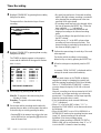
Time Search ...................................................................... 2-10
Playback During Recording (HSR-2/2P only)............. 2-12
Chapter 3
Convenient
Recording/Playback
Functions
Timer Recording .............................................................3-1
Alarm Recording............................................................. 3-4
Repeat Recording........................................................... 3-7
Series Recording ............................................................3-8
Alarm Search ..................................................................3-9
HDD Recording/Playback ............................................3-11
High-Speed Playback ...................................................3-12
Back Space Editing ......................................................3-13
Rec End Search ............................................................ 3-14
Changing the Cassette During Recording .................3-15
English
Table of Contents

Table of Contents
2 Table of Contents
Chapter 4
Menu Operations
Menu Operations ............................................................ 4-1
Layered Structure of the Menu Items ................................. 4-1
Basic Display Layout .......................................................... 4-2
Keys Used for Menu Operations......................................... 4-2
Setting the Menu Items ....................................................... 4-3
Returning to the Default Settings - Initializing ................... 4-4
Menu Items...................................................................... 4-5
Top Menu (First Layer)....................................................... 4-5
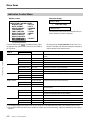
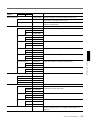
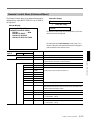
Image Control Menu ........................................................... 4-6
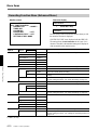
Indication Control Menu ..................................................... 4-8
Recording Function Menu (Enhanced Menu)................... 4-10
Function Control Menu ..................................................... 4-11
Remote Control Menu (Enhanced Menu) ......................... 4-13
Maintenance Menu (Enhanced Menu).............................. 4-15
Chapter 5
Connections and
Preparations
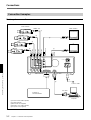
Connections ..................................................................5-1
Video Cameras.................................................................... 5-1
Video Monitors ................................................................... 5-1
Remote Controls ................................................................. 5-1
Connection Examples ......................................................... 5-2
Setting the Clock ............................................................ 5-6
Settings ...........................................................................5-7
Selecting the Enhanced Menu Mode .................................. 5-7
Setting the Cameras to Use ................................................. 5-7
Setting Camera Names........................................................ 5-8
Setting the Display Structures............................................. 5-9
Setting the Automatic Change Cycle ................................ 5-11
Setting the Recording Modes............................................ 5-12
Setting Passwords ............................................................. 5-15
Setting the Pre-Reverse Time (HSR-2/2P only) ............... 5-17

Table of Contents 3
Chapter 6
Maintenance and
Troubleshooting
Maintenance.................................................................... 6-1
Condensation....................................................................... 6-1
Head Cleaning..................................................................... 6-1
Regular Checks ................................................................... 6-2
Troubleshooting .............................................................6-4
Error Codes and Messages.................................................. 6-5
Appendices
Notes on Use.................................................................. A-1
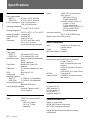
Specifications ................................................................ A-2
Index .................................................................................I-1

Chapter 1 Overview
Chapter 1 Overview 1-1
Chapter 1
Overview
Features
The HSR-1/1P/2/2P Digital Surveillance Recorder is a
hybrid security recorder that records pictures from
multiple surveillance video cameras with a high
picture quality for long periods of time.
The differences between the HSR-2/2P and the HSR-1/
1P are described clearly in the manual. For anything
not mentioned, the operating procedure of the HSR-2/
2P and the HSR-1/1P is the same.
Versatile Processing of
Numerous Images
Four alternative picture quality modes
The HSR-1/1P/2/2P can be switched among four levels
of picture quality: Super, High, Middle and Low
modes. This enables the appropriate balance between
picture quality and recording time to be selected
depending on the application. Super mode provides
excellent picture quality with a horizontal resolution of
more than 500 TV lines. High mode provides higher
quality than that of conventional equipment, with
resolution close to that of the S-VHS format and much
higher S/N ratio.
By selecting Middle or Low mode, you can prolong
recording time compared with the upper modes.
Large storage capacity
Using DV cassette tape (270-minute tape) as the
storage medium, the HSR-1/1P/2/2P offers a large
storage capacity of more than 60 gigabytes.
Long recording time
With its long-time recording capability, the HSR-1/1P/
2/2P releases you from frequent tape changes.
High refresh rate
The HSR-1/1P/2/2P is capable of recording images at
a high refresh rate (0.4 seconds at minimum) for each
camera, so you no longer have to worry about failing
to record key scenes.
High Reliability, Low Maintenance
Reduced use of tape mechanism
The hybrid configuration, with a hard disk and DV
tape drive, makes it possible to achieve higher
reliability. The tape transport and heads of the HSR-1/
1P/2/2P are idle most of the time because the DV tape
drive works only while recording the image data being
transferred from the hard disk.

Chapter 1 Overview
1-2 Chapter 1 Overview
Multiple Protection
In case of the failure of the DV tape drive, recording
operation continues on the built-in hard disk.
Conversely, the HSR-1/1P/2/2P records the image data
directly onto the DV tape if the hard disk fails. (In
some cases, some of the data may be lost.)
For additional protection, the HSR-1/1P/2/2P always
checks whether data is accurately recorded onto a tape.
If a recording failure is detected, the HSR-1/1P/2/2P
re-records the same data onto the tape.
Less Space Required
Compact body
The HSR-1/1P/2/2P features a compact body and is
similar in width to a 14-inch monitor.
Compact storage medium
Using DV cassettes of only 1/3 the volume of VHS
cassettes means your tape library takes up much less
space.
System Versatility
16 Camera inputs
The HSR-1/1P/2/2P has four camera inputs as
standard. Up to three optional HSRA-11, four-input
boards can be installed, so up to 16 camera inputs can
be provided.
Built-in multiplexing capability
The HSR-1/1P/2/2P has built-in multiplexing
capability, which allows independent recording and
monitoring. There is also a choice of various
monitoring patterns by freely assigning multiple
cameras to a single monitor.
Output for a second monitor
The HSR-1/1P/2/2P has two monitoring outputs A and
B, for which output images can be independently
selected. For example, it is possible to monitor the
image from one key camera on the B monitor, while
checking playback on the A monitor.
Flexible camera assignment
There are five preset recording modes, which can be
flexibly combined with your choice of picture quality
mode, tape length, recording time, number of camera
inputs and the recording cycle of each camera. This
feature allows you to assign cameras as you like. It is
possible, for instance, to record from all the cameras in
High mode during the day and then select some of these
cameras to be recorded from in Super mode at night.
RS-232C interface
The HSR-1/1P/2/2P is equipped with an RS-232C
interface for communication with external equipment
such as a personal computer, to facilitate machine
control, and user data read/write. You may also use this
port for connecting the optional SNT-V304 video
network station.
37-pin parallel port
The HSR-1/1P/2/2P has a 37-pin parallel I/O interface,
whose pin functions can be freely configured for a
particular application.
Recording/Playback Systems Not
to Miss Any Important Scenes
Playback During Recording (HSR-2/2P only)
You can check the latest recorded images by reversing
the recording for the desired length of time (from 1 to
99 minutes) without stopping recording in progress.
When checking, you can also search for a specific
image by using the time search and alarm search
functions. Images recorded on other cassettes can also
be played during recording by changing cassettes.
Features

Chapter 1 Overview
Chapter 1 Overview 1-3
Flexibility in Alarm Recording modes
To capture more and even sharper images, the HSR-1/
1P/2/2P not only changes its recording mode to the
higher refresh and higher picture quality mode on
alarm, but also performs interleaved recording, which
accelerates the recording cycle of the camera in alarm
status.
It can also record images from the camera in alarm
status only for a preset duration. In addition, since
alarm and timer recordings can be combined, the HSR-
1/1P/2/2P can be set to normal recording mode during
office hours and set to alarm recording at night.
Continuous recording function
The recorder can continuously record images, even
while you are changing or rewinding the tape, so you
don’t have to worry about the breakup of a recording.
Sophisticated security function
The key-lock function may prevent accidents, such as
inadvertent break-off of important recording.
For higher security, you can specify passwords at three
levels.
Watermark
Using an original watermark system, the HSR-1/1P/2/
2P can identify image data that has been artificially
altered. When alteration is detected, a message is
displayed on screen.
Intelligent search functions
Time search/alarm search
You can easily locate the picture from a specific date
and time.
With a tape on which alarm recordings have been
made, you can locate a specific picture after checking
the list of those recordings.
Variable-speed search with a Jog/Shuttle dial
By connecting the optional SVRM-100A remote
control unit, noiseless picture search can be carried out
using its Jog/Shuttle dial.
Rec End search
The recording end point on a tape can be easily
located.
Quick recording start
The HSR-1/1P/2/2P can start recording the moment
power is turned on. This allows immediate recovery
of recording after a power failure.
Pre-alarm recording
Thanks to the Pre-alarm recording capability,
recording can be started before catching a trigger
signal, thus chances are you’ll have the information
you need on tape
High-quality frame recording
By selecting Frame Rec mode, you can record a single
frame in response to an alarm in Hyper mode, which
provides higher resolution than Super mode.
Power-failure backup function
The HSR-1/1P/2/2P is equipped with a protection
circuit (memory-backup circuit with a rechargeable
battery) to prevent loss of video data caused by power
failure.
If the power fails during recording, the protection
circuit activates, and stores video data for 24 hours.
When power is restored, the unit automatically
resumes recording mode and records the stored video
data on the tape.
Notes
• At least 24 hours with the power on is required to
fully charge the battery.
• Several frames captured immediately before the
power failure may be lost.

Chapter 1 Overview
1-4 Chapter 1 Overview
Optional Devices
HSRA-11 Input Board
Up to three HSRA-11 boards can be mounted in the
recorder and add four VIDEO IN connectors each.
For board installation, refer to the manual for the HSRA-11.
SVRM-100A Remote Control Unit
The HSR-1/1P/2/2P can be controlled at hand.
For details, see “Connection for remote control”(page 5-5).
SNT-V304 Video Network Station
By connecting the SNT-V304 to the HSR-1/1P/2/2P,
the recorder can be controlled by a personal computer
via a network such as a LAN or WAN. In this way
you can totally control the surveillance systems in
various locations from a distance.
Note
Tapes recorded on this unit cannot be played on
other DV cassette players. Conversely, tapes
recorded on other DV cassette recorders cannot be
played on this unit.
Features

Chapter 1 Overview
Chapter 1 Overview 1-5
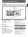
Locations and Functions of Parts
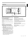
Front Panel
5 Camera number/numeric keys
Flash or light in green or amber depending on the
conditions.
When monitoring and playback, they function as the
keys for camera selection.
In menu operations or when releasing the key lock,
they function as the numeric keys for entering numeric
values or the password.
monitor playback menu operation
Off Disabled
1)
No image Not operable
recorded
2)
Green Available for Available for Numeric inputs
monitor
3)
playback valid
Amber being monitored
4)
being played –
1) The key for any camera set to NO for Camera
Connection of the Image Control menu (page 5-7) does
not light.
2) The key for any camera which has been set to NO REC
on the Rec Function menu (page 5-13) when recording
was made does not light.
3) The key for any camera for which no signal is being
supplied flashes in a slow cycle.
4) The key for any camera whose signal is being displayed
on a full screen flashes in a fast cycle.
1 Opening for cassette compartment
Insert a DV-format cassette of standard or mini size.
When inserting a mini-sized cassette, locate it in the
center of the opening.
For compatible cassettes, see “Handling Cassettes” on
page 2-1.
2 EJECT button
Press to eject the cassette.
3 Cassette indicator (green)
Lights when a cassette is loaded. It flashes while the
cassette is being ejected.
4 REC (recording) indicator (red)
Lit during recording.
It rapidly flashes during recording on the hard disk
only, such as in Playback During Recording (HSR-2/
2P) or while changing the cassette with continuous
recording ON (HSR-1/1P). To record on tape, follow
the displayed guidance which may prompt you to
insert a cassette, etc., and return to the normal
playback mode.
S
DIGITAL SURVELLANCE RECORDER HSR-1
DIGITAL
TIMELAPSE
CONTROL-S
REC
EJECT
FRAME STOPFRAMEREC
F FWDPLAYREW
‚
◊
√
ı ∫
§
·º
¶π® æ
LOCK
TIME
SEARCH
ALARM
SEARCH
CURSOR
MENU
SET/YES
RESET/NO
†
10 11 12
13 14 15 16
1234
5678
9
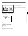
4 Indication window
1 Opening for cassette compartment
2 EJECT button
3 Cassette indicator
4 REC indicator
5 Camera number/numeric keys
6 CONTROL-S connector
1 Tape transport control block
2 Menu operation block
3 Search operation block

Chapter 1 Overview
1-6 Chapter 1 Overview
Locations and Functions of Parts
6 CONTROL-S (S control input) connector
(stereo mini jack)
By connecting a controller, such as the SVRM-100A,
equipped with an S control output to this connector,
tape transport on this recorder can be remotely
controlled.
1 Tape transport control block
1 LOCK key and indicator
Press this key to turn on/off the key-lock function
(provided to prevent misoperation).
The LED indicator (red) lights when the function is on.
When this indicator is lit, other keys are disabled. To
release the lock, press the LOCK key again.
A four-digit password to release the lock can be
specified by using the Function Control menu.
For details, see “Setting Passwords” on page 5-16.
2 REW 0 (rewind) key and indicator
Press this key to rewind the tape. The LED indicator
(green) lights.
This key functions as the reverse search key during
playback.
3 PLAY ( key and indicator
Press this key to start playback. The LED indicator
(green) lights.
On the HSR-2/2P, this key also functions as the PRE
REVERSE PLAY key. When this key is pressed
during recording, playback is performed without
stopping recording.
For details, see “Playback During Recording” on page 2-12.
4 F FWD ) (fast forward) key and indicator
Press this key to fast-forward the tape. The LED
indicator (green) lights.
This key functions as the forward search key during
playback.
5 REC r (record) key
Press this key to start recording.
6 FRAME ' key
Press this key to reverse the picture by one frame.
7 STOP p key
When you press this key during playback, playback
ends. When you press this key during recording, a
message to confirm that you want recording to stop is
displayed.
With the HSR-2/2P, guidance for the next operation is
displayed when you press this key in Playback During
Recording mode.
8 FRAME 7 key
Press this key to advance the picture by one frame.
2 Menu operation block
1 MENU key
Press this key to enter Menu mode. Press again to exit
the mode.
2 CURSOR B/b keys
Used to move from one layer to another in Menu
mode.
While monitoring a picture, you can switch pages
(different camera configuration with the same screen
divisions) with these keys.
FRAME STOPFRAMEREC
F FWDPLAYREW
‚·º
¶π®æ
LOCK
1 LOCK key and indicator
2 REW 0 key and indicator
3 PLAY ( key and indicator
4 F FWD ) key and
indicator
5 REC r key
6 FRAME ' key
7 STOP p key
8 FRAME 7 key
CURSOR
MENU
SET/YES
RESET/NO
◊
√
ı ∫
5 RESET/NO key
1 MENU key
2 CURSOR B/b keys
3 CURSOR V/v keys
4 SET/YES key

Chapter 1 Overview
Chapter 1 Overview 1-7
3 CURSOR V/v keys
Used to move within a single layer in Menu mode.
While monitoring a picture, you can switch screen
division configurations with these keys.
4 SET/YES key
Press this key to register your menu settings.
This key also functions as the YES answer key for
YES/NO questions.
5 RESET/NO key
In normal operation mode, press this key to reset the
tape counter value in the indication window.
In menu mode, this key functions as the NO answer
key for YES/NO questions.
3 Search operation block
1 TIME SEARCH key
Press this key to locate a picture from a specific date
and time (Time Search). You can also locate the
recording end on a tape with this key (Rec End
Search).
For details, see “Time Search” on page 2-10 and “Rec End
Search” on page 3-14.
2 ALARM SEARCH key
To display the list of alarm recordings on a tape and
transport the tape to the point of the specified
recording.
For details, see “Alarm Search” on page 3-9.
4 Indication window
1 ALARM indication
Lights when alarm recording is on.
For details, see “Alarm Recording” on page 3-4.
2 CONT (continuous) indication
Lights when continuous recording is set to ON on the
HSR-1/1P. It stays lit on the HSR-2/2P.
For details, see “Changing the Cassette During Recording”
on page 3-15.
3 REPEAT indication
Lights during repeat recording.
For details, see “Repeat Recording” on page 3-7.
4 TIMER indication
Lights when the timer recording is on.
For details, see “Timer Recording” on page 3-1.
5 Tape remaining indication
Lights when a cassette is loaded, showing the
recording capacity remaining on the tape.
The remaining segment(s) will flash when the
remaining recording capacity becomes less than 3
minutes based on the calculation from the Tape Length
setting.
For the Tape Length setting, see “Setting the Recording
Modes” on page 5-12.
TIME
SEARCH
ALARM
SEARCH
2 ALARM SEARCH key
1 TIME SEARCH key
ALARM CONT REPEAT TIMER
S
TIME MODE
E
1 ALARM indication
2 CONT indication
3 REPEAT indication
4 TIMER indication
5 Tape remaining
indication
6 Character display
7 Time data
indication

Chapter 1 Overview
1-8 Chapter 1 Overview
Locations and Functions of Parts
6 Character display
Shows character data, such as the tape counter value
and menu items.
The tape counter value is a relative time (hours,
minutes, seconds), which has the following meaning
according to the mode of this recorder:
In playback mode: The tape position where the
video information being output has been recorded.
In recording mode: The tape position where the
current video information is recorded.
In other modes: The current tape position
Note
As the recorder employs a hybrid configuration of
HDD and tape, the counter value being displayed in
playback may considerably differ from the actual tape
position. Therefore, the tape counter value may jump
when you change the operation from PLAY to F.FWD/
REW mode.
7 Time data indication
Shows the time to record on a single tape (Time mode)
in hour units.
By setting “Front Time Disp” on the Indication
Control menu (page 4-8), the tape remaining time for
recording or current time can also be displayed in this
section.

Chapter 1 Overview
Chapter 1 Overview 1-9
Rear Panel
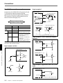
1 VIDEO IN (video input) connectors (BNC type)
and 75-ohm termination switches
For connecting video cameras.
Connectors 1 to 4 are provided as the standard inputs.
Connectors 5 to 16 can be added, four additionally
connectors for each optional HSRA-11 input board
mounted.
The termination switches are normally used in the ON
position.
For mounting an input board, see the instruction manual for
the HSRA-11.
2 VIDEO OUT (video output) connectors
S VIDEO (luminance/chroma signal output)
connector (4-pin): Outputs Y/C-separated S video
signals. Connect via a cable to the S video input of
a video monitor.
A (A image output) connector (BNC type): Outputs
composite video signals for monitoring. Character
signals are superimposed on the output signal
depending on the settings made on the Indication
Control menu (page 4-8).
B (B image output) connector (BNC type): Outputs
composite video signals. The signal to be output is
normally the same as that from the A connector.
The Image Control menu (page 4-6) permits you to
specify use of this output exclusively for a specific
camera. Note that the character signal is not
superimposed with such usage.
3 POWER switch
For turning on/off the power to the recorder.
4 PARALLEL I/O connector (37-pin)
Used to input/output various control signals or to
supply control voltages.
You can use 24 pins for inputs and 8 pins for outputs.
The functions of these pins can be assigned from the
Remote Control menu (page 4-13).
5 RS-232C connector (9-pin)
Connect an editor or computer, via an RS-232C cable.
6 AC IN connector
Connect an AC power source via the supplied AC
power cord.
VIDEO IN VIDEO OUT
PARALLEL I/O RS-232C
S VIDEO
1
2
3
4
5
6
7
8
9
10
11
12
13
14
15
16
B
A
POWER OFF ON
75Ω
ONOFF
75Ω
ONOFF
75Ω
ONOFF
75Ω
ONOFF
⁄AC IN
1 VIDEO IN connectors and 75-ohm termination switches
2 VIDEO OUT connectors
3 POWER switch
4 PARALLEL I/O connector
5 RS-232C connector
6 AC IN connector

Chapter 1 Overview
1-10 Chapter 1 Overview
REC1 NORMAL 12 31 1999 FRI 11:59:59 AM
xxxxH xx.xS SUPER ALARM ERRORxx-xxx HDD
1 XXXXXXXXXX NOT ORIGINAL
ALARM
Locations and Functions of Parts
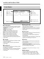
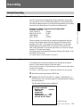
Screen Displays
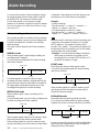
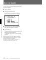
1 Recording modes
When recording or monitoring, the currently selected
mode and recording mode number (REC1 to REC5)
are displayed.
NORMAL: Normal recording
TIMER: Timer recording
ALARM: Alarm recording in Normal mode
INT-A: Alarm recording in Interleave mode
PRE-A: Alarm recording in Prealarm mode
EVT-A: Alarm recording in Event mode
FRM-A: Alarm recording in Frame mode
These items are not displayed during playback.
Whether to display them can be set on the Indication
Control menu.
2 Time mode
When recording or monitoring, the currently selected
Time mode is displayed.
Whether to display it can be set on the Indication
Control menu.
3 Recording cycle
When recording or monitoring, the currently selected
Recording cycle is displayed.
During playback, that used for recording is displayed.
Whether to display it can be set on the Indication
Control menu.
4 Image quality mode
When recording or monitoring, the currently selected
Image quality mode is displayed.
During playback, that used for recording is displayed.
Whether to display them can be set on the Indication
Control menu.
5 Camera name
When recording or monitoring, the name specified for
the current camera is displayed.
During playback, the camera name recorded on the
tape is displayed.
The names of the cameras and whether to display them
can be set on the Indication Control menu.
6 Date/time
When recording or monitoring, the current date and
time are displayed.
During playback, the date and time when the picture
was recorded are displayed.
Whether to display them and the display format can be
set on the Indication Control menu.
For the Indication Control Menu, see Chapter 4 “Menu
Operations.”
7 HDD indication
If no tape is loaded in the recorder when some
information that has not been recorded on a tape
remains on the HDD, an “HDD” indication flashes.
For details, see “HDD Recording/Playback” on page 3-11.
5 Camera name
1 Recording modes
0 ALARM indication (lower)
!¡ NOT ORIGINAL indication
7 HDD indication
9 ALARM indication (upper)
8 Status indication
2 Time mode
3 Recording cycle
4 Image quality mode
6 Date/time

Chapter 1 Overview
Chapter 1 Overview 1-11
8 STATUS indication
The current operating mode (REC, PLAY, F FWD,
REW, etc.) is displayed.
9 ALARM indication (upper)
If there is either an alarm input common to all cameras
or an alarm input from a certain camera to the parallel
input, the indication “ALARM” is superimposed on
the upper portion of the screen, regardless of the
screen display currently selected. This indication also
appears even during playback if any new alarm input
to the recorder is generated.
0 ALARM indication (lower)
If there is an external alarm input, the indication
“ALARM” is superimposed on the lower portion of
the screen. As this information is recorded on the tape,
the indication is also obtained in playback.
!¡ NOT ORIGINAL indication
Thanks to the original watermark system, a “NOT
ORIGINAL” indication is superimposed, if the image
being played may have been artificially altered.
This indication can be seen only in Still mode (either
FRAME key pressed) with the full-screen display.
Note
This indication is disabled in alarm recording in
FRAME mode, in Playback During Recording (HSR-
2/2P) mode, or when you switch the unit from high-
speed playback to variable playback.

Chapter 2 Basic Operations
Chapter 2 Basic Operations 2-1
Chapter 2
Basic Operations
Handling Cassettes
Usable Cassettes
The following standard- and mini-sized cassettes of DV-format can be
used with this recorder.
Model name Size
DV- and PDV-series, such as DV-270RM and PDV-184N Standard
DVM- and PDVM-series, such as DVM-30MM and PDVM-40N Mini
The number included in the name of a DV- or DVM-series model indicates the
tape length (unit: minute). (Ex.: 270 minutes with DV-270RM).
In case of a PDV- or PDVM-series model, the value obtained by multiplying the
number included in the name by 1.5 corresponds the tape length (unit: minute).
(Ex.: 276 minutes with PDV-184N).
Notes on usage
• When a cassette is to be stored for a long time, rewind the tape to the
beginning, mount it in the original case, and place it vertically. Leaving a
cassette lying flat may cause noisy pictures.
• If any undue force is applied to the cassette, such as by dropping it, the
tape may become slackened, causing abnormal recording/playback.
Before using a cassette, be sure to check that the tape is not slacked.
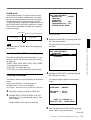
To check the tape slack
Gently turn the reel in the direction
of the arrow using a paper clip or
equivalent. If there is no slack, the
reel will not rotate. Then, insert the
cassette in the recorder and remove
it after about 10 seconds.
Paper clip, or
equivalent
Reel

Chapter 2 Basic Operations
2-2 Chapter 2 Basic Operations
To prevent unintentional erasure
Set the REC/SAVE switch to the SAVE position.
To rerecord on a cassette
Return the REC/SAVE switch to the REC position. No recording will be
made on a cassette with the switch set to SAVE.
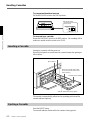
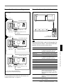
Inserting a Cassette
Insert/eject a cassette with the power on.
Open the front panel cover and insert the cassette through the opening as
shown below.
The cassette is automatically pulled into the operating position and the
cassette indicator lights up.
Ejecting a Cassette
Press the EJECT button.
The cassette indicator flashes while the cassette is being ejected.
Handling Cassettes
REC
SAVE
REC/SAVE switch
Set to SAVE.
EJECT button
Cassette indicator
Mini-sized cassette (Align it with
the concave portion at the center
of the opening.)
Standard-sized cassette
With the tape window facing upward
S
REC
EJECT
‚
§
·º
¶π® æ
†

Chapter 2 Basic Operations
Chapter 2 Basic Operations 2-3
Monitoring Picture
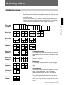
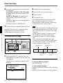
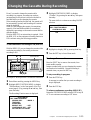
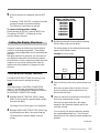
Dividing the Screen
In addition to the capability to show the picture from a specified camera on
the full screen, this recorder has a multiplexer function to divide the screen
into multiple divisions and permit you to view the pictures from multiple
cameras at a glance.
In screen division modes, you can select the respective number of pages
(the same divisions with different camera configurations) for monitoring.
The following camera numbers have been assigned at the factory.
Full screen
(16 pages)
4 divisions
(4 pages)
6 divisions
(3 pages)
7 divisions
(3 pages)
8 divisions
(2 pages)
9 divisions
(2 pages)
10 divisions
(2 pages)
13 divisions
(1 page)
16 divisions
(1 page)
Camera assignments
You can assign the connected cameras to any division
by using Moni Display Structure of the Image Control
menu.
For the assigning method, see “Setting the Display
Structures” on page 5-9.
Border lines
You can select whether the lines are to be displayed,
and if so, in black or in white on the Indication Control
menu.
Superimposing
According to settings made on the Indication Control
menu, various information, such as the camera
number/name, date/time, etc. can be superimposed
onto the signal input from a camera.
The type of superimposed characters can also be set.
See Chapter 4 “Menu Operation” for the Indication Control
menu and “Setting Camera Names” on page 5-8 for camera
names.
12
34
56
78
910
11 12
13 14
15 16
1
2
3
4
5
6
7
8
9
10
11
12
13
14
15
16
1
3
2
45
67
1
3
2
89
10 11
1
3
2
12 13
14 15
2
13
4
5678
9
110
11
12 13 14 15
12
3456
78910
12
11 12 13 14
15 16
123
456
789
1
2
3
456
1
7
8
91011
1
12
13
14 15 16
10 11 12
13 14 15
16
1
23
45
6789
10 11 12 13
1234
5678
9 101112
13 14 15 16
Page 1 Page 2 Page 3 Page 4
Page 1 Page 2 Page 3
Page 1 Page 2 Page 3
Page 1 Page 2
Page 1 Page 2
Page 1 Page 2

Chapter 2 Basic Operations
2-4 Chapter 2 Basic Operations
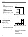
Switching the Pictures
The number keys of the cameras whose pictures can be monitored flash in
green.
To select the picture(s) for monitoring, use the flashing camera number
keys or the CURSOR V/v/B/b keys.
For connections and Image Control menu operation, see Chapter 5 “Connections
and Preparations.”
To select a specific camera
Press the number key corresponding to the camera to be monitored.
The key then flashes in amber, and the picture of the selected camera is
displayed on the full screen.
Press the same key again to return to the pervious condition.
To select a divided screen
Multiple camera pictures can be monitored by selecting the screen division
mode.
To change the structure
Press the V or v key.
Each time you press either of the keys, the display switches to the next of
night patterns, from the full screen to 16-division mode.
To change the pages
Press the B or b key.
The pages are cyclically switched.
To automatically switch pages
The pages of the structure selected using the V or v key are automatically
switched at the cycle specified in the range of 1 to 60 seconds.
Set MONITOR to AUTO on the Image Control menu.
For the settings, see Chapter 5 “Connections and Preparations.”
Monitoring Picture
CURSOR V/v/B/b keys Camera number keys
S
DIGITAL SURVELLANCE RECORDER HSR-1
DIGITAL
TIMELAPSE
CONTROL-S
REC
EJECT
FRAME STOPFRAMEREC
F FWDPLAYREW
‚
§
·º
¶π® æ
LOCK
TIME
SEARCH
ALARM
SEARCH
CURSOR
MENU
SET/YES
RESET/NO
†
10 11 12
13 14 15 16
◊
√
ı ∫
1234
5678
9
Page is loading ...
Page is loading ...
Page is loading ...
Page is loading ...
Page is loading ...
Page is loading ...
Page is loading ...
Page is loading ...
Page is loading ...
Page is loading ...
Page is loading ...
Page is loading ...
Page is loading ...
Page is loading ...
Page is loading ...
Page is loading ...
Page is loading ...
Page is loading ...
Page is loading ...
Page is loading ...
Page is loading ...
Page is loading ...
Page is loading ...
Page is loading ...
Page is loading ...
Page is loading ...
Page is loading ...
Page is loading ...
Page is loading ...
Page is loading ...
Page is loading ...
Page is loading ...
Page is loading ...
Page is loading ...
Page is loading ...
Page is loading ...
Page is loading ...
Page is loading ...
Page is loading ...
Page is loading ...
Page is loading ...
Page is loading ...
Page is loading ...
Page is loading ...
Page is loading ...
Page is loading ...
Page is loading ...
Page is loading ...
Page is loading ...
Page is loading ...
Page is loading ...
Page is loading ...
Page is loading ...
Page is loading ...
Page is loading ...
Page is loading ...
Page is loading ...
Page is loading ...
Page is loading ...
Page is loading ...
Page is loading ...
Page is loading ...
Page is loading ...
Page is loading ...
Page is loading ...
Page is loading ...
Page is loading ...
Page is loading ...
-
 1
1
-
 2
2
-
 3
3
-
 4
4
-
 5
5
-
 6
6
-
 7
7
-
 8
8
-
 9
9
-
 10
10
-
 11
11
-
 12
12
-
 13
13
-
 14
14
-
 15
15
-
 16
16
-
 17
17
-
 18
18
-
 19
19
-
 20
20
-
 21
21
-
 22
22
-
 23
23
-
 24
24
-
 25
25
-
 26
26
-
 27
27
-
 28
28
-
 29
29
-
 30
30
-
 31
31
-
 32
32
-
 33
33
-
 34
34
-
 35
35
-
 36
36
-
 37
37
-
 38
38
-
 39
39
-
 40
40
-
 41
41
-
 42
42
-
 43
43
-
 44
44
-
 45
45
-
 46
46
-
 47
47
-
 48
48
-
 49
49
-
 50
50
-
 51
51
-
 52
52
-
 53
53
-
 54
54
-
 55
55
-
 56
56
-
 57
57
-
 58
58
-
 59
59
-
 60
60
-
 61
61
-
 62
62
-
 63
63
-
 64
64
-
 65
65
-
 66
66
-
 67
67
-
 68
68
-
 69
69
-
 70
70
-
 71
71
-
 72
72
-
 73
73
-
 74
74
-
 75
75
-
 76
76
-
 77
77
-
 78
78
-
 79
79
-
 80
80
-
 81
81
-
 82
82
-
 83
83
-
 84
84
-
 85
85
-
 86
86
-
 87
87
-
 88
88


Sony HSR-1P User manual
- Category
- Cassette players
- Type
- User manual
Ask a question and I''ll find the answer in the document
Finding information in a document is now easier with AI
Related papers
Other documents
-
Panasonic AGTL750 Operating instructions
-
Sanyo VAC-60 Operating instructions
-
JVC VCR SR-9168U User manual
-
-
-
HANYOUNG NUX HSR-3 Owner's manual
-
-
-
-
Hitachi DV-RV8500E/UK User manual