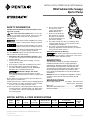
Hydromatic BV40 Submersible Sewage Ejector Pump Owner's manual
- Category
- Water pumps
- Type
- Owner's manual

SAFETY INFORMATION
Carefully read and follow all safety instructions in this
manual or on pump.
This is the safety alert symbol. When you see this
symbol on your pump or in this manual, look for one of the
following signal words and be alert to the potential for
personal injury!
warns about hazards that will cause serious
personal injury, death or major property damage if ignored.
warns about hazards that can cause serious
personal injury, death or major property damage if ignored.
warns about hazards that will or can cause
minor personal injury or property damage if ignored.
The word NOTICE indicates special instructions which are
important but not related to hazards.
1. Read these rules and instructions carefully. Failure
to follow them could cause serious bodily injury and/or
property damage.
2. Check your local codes before installing. You must
comply with their rules.
3. Vent sewage or septic tank according to local codes.
4. Do not install pump in any location classified as
hazardous by National Electrical Code, ANSI/NFPA
80-1984 or the Canadian Electrical Code.
Hazardous voltage. Can shock,
burn, or kill. During operation the pump is in water.
To avoid fatal shocks, proceed as follows if pump needs
servicing:
Do not smoke or use devices that can generate sparks in a
septic (gaseous) environment.
5A. Disconnect power to outlet box before unplugging pump.
5B. Take extreme care when changing fuses. Do not stand
in water or put your finger in the fuse socket.
5C. Do not modify the cord and plug. When using the cord
and plug, plug into a grounded outlet only. When wiring
to a system control, connect the pump ground lead to
the system ground.
6. Be sure that construction
and access to septic
sumps conform with all
OSHA requirements.
7. Do not run the pump dry.
Dry running can overheat
the pump, (causing burns
to anyone handling it) and
will void the warranty.
8. The pump normally runs hot. To avoid burns when
servicing pump, allow it to cool for 20 minutes after
shutdown before handling it.
9. The pump is permanently lubricated. No oiling or
greasing is required in normal operation. for overhaul,
see instructions under “Service”.
California Proposition 65 Warning
This product and related accessories contain
chemicals known to the State of California to cause cancer,
birth defects or other reproductive harm.
DESCRIPTION
This submersible sewage ejector pump is designed for
residential wastewater removal, sewage applications,
sump drainage, dewatering and flood control. Units have
built in thermal overload protection with automatic reset.
The mechanical seal and bearings on the motor shaft are
permanently lubricated. Stainless steel hardware and a
heavy duty lift out handle allow for easy disassembly after
extended use.
NOTICE: This unit is not designed for applications involving
salt water or brine! Use with salt water or brine will void
warranty.
SPECIFICATIONS
Power supply required ............. See “Motor, Switch and Cord
Specifications” chart below
Motor duty .............................................................Intermittent
Maximum Liquid Temperature .......................... 120°F (49°C)
Discharge Adapter ..................................................... 2" NPT
Motor Individual Cord Switch Setting Discharge
Model Motor Full Branch Circuit Length in inches (mm)
Adapter
Number HP Voltage Load Amps Required (Amps) in ft. (m)
On Off Size
BV40AW1 4/10 115/1 12.6 15 10 (3.0) 12-1/2 (317) 6-1/2 (165) 2"
BV40AD1 4/10 115/1 12.6 15 10 (3.0) 14-1/2 (368) 6 (152) 2"
MOTOR, SWITCH, & CORD SPECIFICATIONS
© 2013 Pentair, Ltd. All Rights Reserved. W-03-446 (Rev. 02/21/13)
293 WRIGHT STREET, DELAVAN, WI 53115 WWW.HYDROMATIC.COM
PH: 8889578677
InstallatIon, operatIon & parts Manual
BV40 Submersible Sewage
Ejector Pump

PERFORMANCE
INSTALLATION
Hazardous voltage. Can shock, burn or kill.
Do not lift pump by the power cord. See “Cord Lift Warning”
below.
NOTICE: Install the pump on a hard, level surface (cement,
asphalt, etc.). Never place the pump directly on earth, clay
or gravel surfaces. Install the pump in a sump basin with a
minimum diameter of 18" (46cm).
Piping
Piping must not be smaller than pump discharge.
When installed in a sewage system, the pipe must be
capable of handling semi-solids of at least 2" (51mm) in
diameter.
When installed in an effluent system, the pipe must be
capable of handling semi-solids of at least 3/4" (19mm) in
diameter.
The rate of flow in the discharge pipe must keep any solids
present in suspension in the fluid. To meet minimum flow
requirements (2 feet per second in the discharge line), size
the pipe as follows:
A Pipe Size Of: Will Handle a Flow Rate Of:
1-1/2" (38mm) 12 GPM
2" (51mm) 21 GPM
2-1/2"(64mm) 30 GPM
3"(76mm) 48 GPM
In a sewage system use a 2" (51mm) check valve in pump
discharge to prevent backflow of liquid into sump basin. The
check valve should be installed 12 – 18” (317 – 457mm) above
the pump discharge and be a free flow valve that will easily
pass solids. Be sure check valve installation complies with local
codes.
In an effluent system use a 1-1/2" (38mm) check valve in
pump discharge to prevent backflow of liquid into sump basin.
NOTICE: For best performance of check valve when handling
solids, do not install it with the discharge more than 45° above
the horizontal. Do not install the check valve in a vertical
position as solids may settle in the valve and prevent it from
opening on startup.
Drill a 3/16" (5mm) hole in the discharge pipe about 1–2"
(25-51mm) above the pump discharge connection (but below
check valve) to prevent airlocking the pump.
Be sure that the wide-angle float switch hangs freely. It should
not be able to come in contact with the sides or bottom of the
sump pit.
Make sure the sump pit is free of any debris that could
obstruct the intake volute or switch.
Use plumbing materials that are approved by local building
codes when connecting pipes between pump and sewer
outlet.
NOTICE: For critical indoor installations where additional high
water protection is desired, install a “Q-Alert” audible alarm
system in the sump pit. For outdoor installations, confer with
your Hydromatic distributor.
Connect the power cord to a 3-prong grounded AC receptacle.
Hazardous voltage. Can shock, burn or kill.
DO NOT remove the grounding pin from the power cord.
Avoid using extension cords or 2-prong adapter plugs.
Insert the piggyback plug that comes from the wide-angle
float switch directly into the power receptacle.
Insert the pump power cord directly into the back of the
piggyback receptacle.
Test the pump installation by filling the sump basin with
enough water to activate the pump and repeat this cycle until
satisfied with pump operation.
Electrical
Hazardous voltage. Can shock, burn, or
kill. When installing, operating, or servicing this pump, follow
the safety instructions listed below.
1. DO NOT splice the electrical power cord.
2. DO NOT allow the plug on the end of the electrical cord
to be submerged.
3. DO NOT use extension cords. They are a fire hazard and
can reduce voltage sufficiently to prevent pumping and/or
damage motor.
4. DO NOT handle or service the pump while it is
connected to the power supply.
5. DO NOT remove the grounding prong from the plug or
modify the plug. To protect against electrical shock, the
power cord is a three-wire conductor and includes a
3-prong grounded plug. Plug the pump into a 3-wire,
grounded, grounding-type receptacle. Connect the pump
according to the NEC or CEC and local codes.
2
1. Attempting to lift or support pump by power cord
can damage cord and cord connections.
2. Cord may pull apart, exposing bare wires with
possibility of fire or electrical shock.
3. Lifting or supporting pump by power cord will
void warranty.
4. Use lifting ring or handle on top of pump for
all lifting/lowering of pump. Disconnect power
to pump before doing any work on pump or
attempting to remove pump from sump.
5753 1207
Risk of electrical shock.
Can burn or kill.
Do not lift pump by
power cord.
WARNING
CORD LIFT WARNING
GPM AT TOTAL FEET
Model 0 5 15 No flow at height
CAPACITY GALLONS/MINUTE
shown below
BV40AW1 78 70 35 20'
BV40AD1 78 70 35 20'

For automatic operation, plug or wire the pump into an
automatic float switch or duplex controller. The pump will run
continuously when plugged directly into an electrical outlet.
Connect or wire pump to its own individual branch circuit
with no other outlets or equipment in the circuit. Size fuses
or circuit breakers according to the “Motor, Switch and Cord
Specifications” chart.
Risk of electrical shock and fire. Can
burn, kill or cause property damage. Be sure that power
supply information (Voltage/ Hertz/Phase) on pump motor
nameplate matches incoming power supply exactly. Install
pump according to all electrical codes that apply.
OPERATION
Risk of fire or explosion. Can cause severe
personal injury, property damage or death. Do not use in
explosive atmospheres. Pump water only with this pump.
NOTICE: Do not allow the pump to run in a dry sump. It will
void the warranty and may damage the pump.
An automatic overload protector in the motor will protect
the motor from burning out due to overheating/overloading.
When the motor cools down, the overload protector will
automatically reset and start the motor.
If the overload trips frequently, check for the cause. It could
be a stuck impeller, wrong/low voltage, or an electrical failure
in the motor. If an electrical failure in the motor is suspected,
have it serviced by a competent repairman.
The pump is permanently lubricated. No oiling or greasing is
required.
Cycle the pump at least once every month to be sure that the
system is working satisfactorily.
NOTE: Any of the following will void the pump warranty:
1. Submerging, plugging, damaging or taping shut a vented
cord.
2. Pumping materials other than those the pump was
designed to pump or continuously pumping water hotter
than 120°F (49°C).
3. Cutting or splicing a power cord or switch cord.
4. Anyone other than an authorized Hydromatic service
technician dismantling the pump.
5. Removing the cord tag from the cord.
SERVICE
General
Hazardous voltage and risk of cord
damage. Can shock, burn, or kill. Before removing the
pump from the basin for service, always disconnect electrical
power to the pump and the control switch. Do not lift the
pump by the power cord. See the “Cord Lift Warning”, Page
2.
Disinfect the Pump
Place the pump in an area where it can be cleaned
thoroughly. Remove all scale and deposits on the pump.
Submerge the complete pump in a disinfectant solution
(chlorox or chlorine bleach) for at least one hour before
disassembling the pump.
The pump motor housing contains a special lubricating oil
which should be kept clean and free of water at all times.
NOTICE: Whenever the motor housing is being removed for
service, remove oil and replace it with new oil at reassembly.
Use only oil listed in parts list in this manual. When filling
with new oil, DO NOT overfill. Be sure that the oil level is
1/4" above the motor windings.
Pump Disassembly
(See “Disinfect the Pump”)
Check Motor Windings
1. Use a quality volt-ohm-meter (VOM) when performing
these inspections.
2. Set the meter to Rx1.
3. Touch both flat prongs of the power cord to the leads of
the VOM and observe the readings:
a. 230 Volt System - 0.8 to 1.1 ohms
b. 115 Volt System - 1.6 to 1.8 ohms
Check Pump Ground
4. Set the meter to Rx100
5. Touch one lead to the grounding pin and the other lead
to one flat prong of the plug. Repeat for the other prong.
6. Reading should be infinity for both prongs.
a. If the reading is anything other than infinity, the stator
must be removed, dried and rechecked.
b. A reading of “0” indicates a dead short. Replace the
stator.
Removing the Pump Housing
1. Remove the oil fill plug from the housing and drain
the pump oil into a clean bucket. A milky appearance
indicates that water has leaked into the oil. Replace
O-rings and/or seals.
2. Remove the three capscrews from the upper motor
housing and remove housing.
NOTICE: Use caution not to damage the two motor leads
that are attached inside the housing.
3. Remove the two motor leads from the cord plug and set
aside.
Removing the Impeller
1. Remove the eight capscrews and separate the volute
from the lower motor housing.
NOTICE: Loctite #277 is used to install the impeller during
assembly. Break this seal to remove the impeller. Hold the
shaft with a screwdriver and use a plastic or rubber mallet to
tap on pump components.
2. Tap the impeller in a counterclockwise direction until it
comes free of the shaft.
3. Remove the four screws and remove the top half of the
volute.
Replacing Ceramic Seal
1. Insert a screwdriver under the ceramic seal and
remove it.
2. Remove the two bolts holding the stator to the seal
housing.
3. Tap the shaft and rotor assembly out.
NOTICE: The lower ball bearing will come out with the shaft
and rotor assembly.
4. Tap out the stationary half of the seal from the top of the
seal plate and wipe clean.
5. Coat the replacement seal with a thin coat of dielectric
oil and push the seal (carbon face out) into the seal plate
with a plastic dowel. Do not damage, scratch or mar the
carbon face of the seal.
3

Pump Assembly
NOTICE: The replacement rotor must be of the same
manufacture as the existing rotor.
1. Push the new rotor shaft and bearing assembly into the
seal plate.
2. Fasten the stator to the seal plate with the two long
capscrews.
3. Tighten the screws evenly and firmly in order to prevent
any misalignment of the rotor and stator.
4. Install the seal plate on the upper volute with four flat-
head screws. Be sure not to chip or scratch the seal
face.
5. Coat the new ceramic rotating seal with a thin coat of
dielectric oil and press it into place on the rotor shaft with
the rubber ring facing the impeller.
NOTICE: The ceramic seal must be kept clean. Any dirt will
cause the seal to fail.
6. Be sure that the shaft is clean.
7. Hold the shaft with a screwdriver and start the impeller
on the shaft one or two turns.
8. Add a drop of Loctite #277 to the threads and screw the
impeller on the rest of the way hand tight.
The impeller will force the ceramic seal into position.
NOTICE: Excessive Loctite on the seal or bearing will cause
the shaft to seize.
9. Install the lower volute and fasten it securely with 8
capscrews.
10. Remove the old square-cut O-ring and install new
square-cut O-ring. Avoid rolling it into position; lubricate
and stretch the new square-cut O-ring to fit.
11. Fasten the motor leads inside the motor housing and
tuck the wires up into the housing to prevent contact with
the rotor.
12. Assemble the motor housing to the seal plate with three
capscrews.
13. Check for seal leaks by pressurizing the pump to 7 to
9 PSI. If air bubbles continue, recheck seals.
14. Fill the motor housing with high-grade transformer oil
(Part No. U197-8A).
15. Adjust the oil level to 1/4" (6 mm) above the motor
windings top plate or to the top of the stator.
NOTICE: Do not fill the motor housing completely. Allow air
space for expansion.
16. Replace the oil fill plug.
17. Recheck the winding resistance before applying power.
18. Plug the power cord into a grounded outlet and check the
pump operation. Motor should run smoothly and be free
of vibration.
4
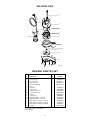
Shaft Seal
Seal Plate
Square-Cut O-Ring
Impeller
Lower Volute
Upper Volute
Motor Housing
Oil Fill
Plug
Capscrews
Capscrews
5737 1207
Pump Disassembly

5
1
2
3
5
4
7A,7B
8
9
10
11
6
5738 1207
EXPLODED VIEW
Key Part Part
No. Description Qty Number
1 Cord 115V 10' 1 14623-010-1
1 Cord 115V 20' 1 14623-020-1
• CordSealRing 1 00139-014-1
2 Motor Housing 1 08507-013-5
3 Square-Cut O-Ring 1 00149-001-1
4 Motor 1 *
5 Seal Plate 1 14599-001-2
6 Upper Volute 1 24637D000
7A Seal Half, Stationary 1 05484-001-1
7B Seal Half, Rotating 1 05484-003-1
8 Impeller 1 08498-005-1
9 Lower Volute 1 2468D000
10 Diaphragm Switch, 115V 10' 1 12752-008-5
10 Diaphragm Switch, 115V 20' 1 12752-009-5
• WideAngleFloatSwitch,115V10' 1 12150-026-5
• WideAngleFloatSwitch,115V20' 1 12150-023-5
• WideAngleFloatSwitch,230V20' 1 13967-025-7
11 Handle 1 08522-006-3
* If motor fails, replace entire pump.
•NotIlustrated
REPAIR PARTS LIST

TROUBLES-REMEDIES
Sudden Starts. If the power is on to the pump when thermal overload resets, the pump may start without
warning. If you are working on the pump, you may get an electrical shock or the impeller may catch fingers or tools.
Disconnect the power before servicing the pump.
A. Pump fails to operate: 1. Check to be sure that power cord is securely plugged into outlet or securely wired
into controller or switch box.
2. Check to be sure you have electrical power. Be sure that the piggyback plugs are
tight.
3. Check that liquid fluid level is high enough to activate switch or controller.
4. Check to be sure that 1/8" (3 mm) vent hole in discharge pipe is not plugged.
5. Check for blockage in pump inlet, impeller, check valve or discharge pipe.
6. Disconnect the pump from the power source for a minimum of 30 minutes to allow
the motor to cool and to protect yourself from sudden starts. See Warning above.
Check for the cause of overheating. Pump is running dry because the float switch
is caught up on something. Inlet pipe is plugged. Outlet pipe is plugged.
7. Motor windings may be open. Take unit to authorized service center.
B. Pump runs, but fails to 1. Be sure all valves in discharge pipe are fully open.
empty sump:
2. Clean out discharge pipe and check valve.
3. Check for blockage in pump inlet or impeller.
4. Pump not sized properly. A higher capacity pump may be required.
C. Pump will not shut off: 1. Check switch for proper operation and location.
See installation instructions for switch.
2. If pump is completely inoperative or continues to malfunction, consult your
local serviceman.
D. Pump run but fails to deliver 1. Check valve may be installed backwards. Be sure that the arrow on valve points in
water: the direction of flow.
2. Pump may be airlocked. Check vent hole in impeller housing.
E. Pump fuse blows or trips 1. Check fuse size.
circuit breaker: Motor runs for 2. Intake opening clogged. Obstructed impeller. Obstructed volute.
short time and stops: 3. Defective stator.
F. Pump runs but delivers small 1. Start and stop pump several times by plugging and unplugging cord.
amount of water: 2. Clear vent hole in impeller cavity.
66

This page intentionally left blank

Limited Warranty
HYDROMATIC warrants to the original consumer purchaser (“Purchaser” or “You”) of HYDROMATIC Sump Pumps,
Effluent Pumps, Sewage Pumps (other than 2-1/2”), and Package Systems, that they will be free from defects in material and
workmanship for the Warranty Period of 36 months from date of manufacture.
Our warranty will not apply to any product that, in our sole judgement, has been subject to negligence, misapplication,
improper installation, or improper maintenance. Without limiting the foregoing, operating a three phase motor with single phase
power through a phase converter will void the warranty. Note also that three phase motors must be protected by three-leg,
ambient compensated, extra-quick trip overload relays of the recommended size or the warranty is void.
Your only remedy, and HYDROMATIC’s only duty, is that HYDROMATIC repair or replace defective products (at
HYDROMATIC’s choice). You must pay all labor and shipping charges associated with this warranty and must request warranty
service through the installing dealer as soon as a problem is discovered. No request for service will be accepted if received after
the Warranty Period has expired. This warranty is not transferable.
EXCEPTIONS: Hydromatic Special Application Pumps, Battery Back-Up Sump Pumps, Filtered Effluent Pumps, Grinder
Pumps, and 2-1/2” Sewage Pumps are warranted for a period of 12 months from date of purchase or 18 months from date of
manufacture, whichever comes first.
HYDROMATIC SHALL NOT BE LIABLE FOR ANY CONSEQUENTIAL, INCIDENTAL, OR CONTINGENT
DAMAGESWHATSOEVER.
THE FOREGOING LIMITED WARRANTIES ARE EXCLUSIVE AND IN LIEU OF ALL OTHER EXPRESS AND IMPLIED
WARRANTIES, INCLUDING BUT NOT LIMITED TO IMPLIED WARRANTIES OF MERCHANTABILITY AND FITNESS FOR
A PARTICULAR PURPOSE. THE FOREGOING LIMITED WARRANTIES SHALL NOT EXTEND BEYOND THE DURATION
PROVIDED HEREIN.
Some states do not allow the exclusion or limitation of incidental or consequential damages or limitations on the duration of an
implied warranty, so the above limitations or exclusions may not apply to You. This warranty gives You specific legal rights and
You may also have other rights which vary from state to state.
This Limited Warranty is effective June 1, 2011 and replaces all undated warranties and warranties dated before June 1, 2011.
HYDROMATIC
293 Wright Street, Delavan, WI 53115
Phone: 888-957-8677 • Fax: 800-426-9446 • Web Site: hydromatic.com
-
 1
1
-
 2
2
-
 3
3
-
 4
4
-
 5
5
-
 6
6
-
 7
7
-
 8
8


Hydromatic BV40 Submersible Sewage Ejector Pump Owner's manual
- Category
- Water pumps
- Type
- Owner's manual
Ask a question and I''ll find the answer in the document
Finding information in a document is now easier with AI
Related papers
-
Hydromatic SKV40 Submersible Sewage Ejector Pump Installation guide
-
-
-
Hydromatic SHEF45 Submersible Effluent Pump Owner's manual
-
-
-
Pentair Sewage Ejector Pump/Basin Package Owner's manual
-
-
-
Other documents
-
Everbilt HDS50 Installation guide
-
Pentair SHEF40 User manual
-
Everbilt HDPS33W User guide
-
Pentair Hydromatic SK60 Owner's manual
-
Pentair B-A1 Hydromatic Submersible Sump Pump Owner's manual
-
Pentair SHEF45 User manual
-
-
none WSSPC5V User guide
-
Bosch HGV423120N/08 Owner's manual
-
red lion RL33CSS Owner's manual