Shimano SL-M2000 Dealer's Manual

Type
Dealer's Manual

This manual is also suitable for

Shimano SL-M2000 is a rapidfire plus shifting lever designed for precise and smooth gear changes, offering enhanced shifting performance for mountain bikes. With its intuitive operation, you can轻松change gears by simply pushing or pulling the lever, allowing you to focus on your ride. Additionally, the SL-M2000 features an adjustable lever position, enabling customization for a comfortable and natural hand position.

Shimano SL-M2000 is a rapidfire plus shifting lever designed for precise and smooth gear changes, offering enhanced shifting performance for mountain bikes. With its intuitive operation, you can轻松change gears by simply pushing or pulling the lever, allowing you to focus on your ride. Additionally, the SL-M2000 features an adjustable lever position, enabling customization for a comfortable and natural hand position.

(English)
DM-MDSL001-01
Dealer's Manual
ROAD MTB Trekking
City Touring/
Comfort Bike
URBAN SPORT E-BIKE
Shifting Lever
RAPIDFIRE Plus
SL-M2000
SL-M3010
SL-M4010
Thumb Shifter
SL-TZ500
2
CONTENTS
IMPORTANT NOTICE .............................................................................................. 3
TO ENSURE SAFETY ............................................................................................... 4
LIST OF TOOLS TO BE USED .................................................................................. 6
INSTALLATION ....................................................................................................... 8
Mounting the shifting lever ........................................................................................................................8
ADJUSTMENT ...................................................................................................... 10
Adjustment of the rear shifting lever .......................................................................................................10
SIS Adjustment ...........................................................................................................................................15
Adjustment of the front shifting lever .....................................................................................................17
MAINTENANCE .................................................................................................... 24
Replacing the inner cable ..........................................................................................................................24
Replacement of the cover ..........................................................................................................................25
3
IMPORTANT NOTICE
IMPORTANT NOTICE
This dealer's manual is intended primarily for use by professional bicycle mechanics.
Users who are not professionally trained for bicycle assembly should not attempt to install the components themselves using the dealer's manuals.
If any part of the information on the manual is unclear to you, do not proceed with the installation. Instead, contact your place of purchase or a local
bicycle dealer for their assistance.
Make sure to read all instruction manuals included with the product.
Do not disassemble or modify the product other than as stated in the information contained in this dealer's manual.
All dealer's manuals and instruction manuals can be viewed on-line on our website (http://si.shimano.com).
Please observe the appropriate rules and regulations of the country, state or region in which you conduct your business as a dealer.
For safety, be sure to read this dealer's manual thoroughly before use, and follow it for correct use.
The following instructions must be observed at all times in order to prevent personal injury and physical damage to equipment and surroundings.
The instructions are classified according to the degree of danger or damage which may occur if the product is used incorrectly.
DANGER
Failure to follow the instructions will result in death or serious injury.
WARNING
Failure to follow the instructions could result in death or serious injury.
CAUTION
Failure to follow the instructions could cause personal injury or physical damage to equipment and surroundings.
4
TO ENSURE SAFETY
TO ENSURE SAFETY
WARNING
When installing components, be sure to follow the instructions that are given in the instruction manuals.
It is recommended that you use only genuine Shimano parts. If parts such as bolts and nuts become loose or damaged, the bicycle may suddenly fall
over, which may cause serious injury.
In addition, if adjustments are not carried out correctly, problems may occur, and the bicycle may suddenly fall over, which may cause serious injury.
Be sure to wear safety glasses or goggles to protect your eyes while performing maintenance tasks such as replacing parts.
After reading the dealer's manual thoroughly, keep it in a safe place for later reference.
NOTE
Be sure to also inform users of the following:
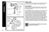
Be sure to keep turning the crank during the shifting lever operation.
You should periodically wash the chainrings in a neutral detergent. In addition, cleaning the chain with neutral detergent and lubricating it can be an
effective way of extending the useful life of the chainrings and the chain.
Read the dealer's manuals for the front derailleur, rear derailleur, and brake.
Products are not guaranteed against natural wear and deterioration from normal use and aging.
For maximum performance we highly recommend Shimano lubricants and maintenance products.
The actual product may differ from the illustration because this manual is intended chiefly to explain the procedures for using
the product.
LIST OF TOOLS TO BE USED
6
LIST OF TOOLS TO BE USED
The following tools are needed to assemble this product.
Tool Tool
5mm hexagon wrench Screwdriver[#2]
Screwdriver[#1] 9mm spanner
INSTALLATION
8
INSTALLATION
Mounting the shifting lever
INSTALLATION
Mounting the shifting lever
SL-TZ500
(A)
Install the brake lever in a position
where it will not obstruct brake
operation.
Do not use in a combination which
causes brake operation to be
obstructed.
(A)
Screwdriver[#2]
Tightening torque
2.5 N·m
NOTE
Do not open the clamp of the lever when
installing, otherwise the cover may be
damaged.
Install the lever unit in a position where it
will not come into contact with the brake
lever when you operate the lever unit from
the low to the top position.
SL-M2000/SL-M3010/SL-M4010
(A)
(A)
5mm hexagon wrench
Tightening torque
5 N·m
NOTE
Use a handlebar grip with a maximum outer
diameter of 36mm.
ADJUSTMENT
10
ADJUSTMENT
Adjustment of the rear shifting lever
ADJUSTMENT
Be sure to follow the sequence described below.
Adjustment of the rear shifting lever
Top adjustment
1
Turn the top adjustment screw for adjustment so that the guide pulley is positioned over the
outer line of the smallest sprocket when viewed from behind.
(A)
Outer line of smallest sprocket
(B)
Guide pulley
(C)
Top adjustment screw
NOTE
The position of the top adjustment screw
differs depending on the model.
A
B
(A)
(B)
(C)
B
A
< Example >
2
After this, install the chain.
11
ADJUSTMENT
Adjustment of the rear shifting lever
Connection and securing of cable
Inserting the inner cable
Insert the inner cable into the outer casing from the end with the marking on it.
Apply grease from the end with the marking in order to maintain cable operating efficiency.
(A)
Marking
(A)
Cutting the outer casing
When cutting the outer casing, cut the opposite end to the end with the marking.
After cutting the outer casing, make the end round so that the inside of the hole has a uniform
diameter.
(y)
Coil tipping over inward
(z)
Coil not tipping over inward
(y) (z)
Bad example Good example
Attach the same outer end cap to the cut end of the outer casing.
(A)
Outer end cap
(A)
12
ADJUSTMENT
Adjustment of the rear shifting lever
SL-M2000/SL-M3010/SL-M4010
(A)
SL-TZ500
(A)
Connect the cable to the rear derailleur.
(A)
Groove
Tightening torque
5 - 7 N·m
NOTE
Be sure that the cable is securely in the
groove.
13
ADJUSTMENT
Adjustment of the rear shifting lever
Adjustment of cable tension
After taking up the initial slack in the
cable, re-secure to the rear derailleur as
shown in the illustration.
Low adjustment
1
While turning the front chainwheel, operate the lever to shift to the lowest gear.
2
Turn the low adjustment screw so that the guide pulley moves to a position directly below
the largest sprocket.
(A)
Largest sprocket
(B)
Guide pulley
(C)
Low adjustment screw
NOTE
The position of the low adjustment screw
differs depending on the model.
(A)
(B)
(C)
A
B
B
A
< Example >
14
ADJUSTMENT
Adjustment of the rear shifting lever
How to use the B-tension adjustment screw
(B)
(C)
(A)
A
A
B
B
A
B
(A)
Largest sprocket
(B)
Smallest sprocket
(C)
B-tension adjustment screw
1
Mount the chain on the smallest chainring and the largest sprocket, and turn the crank arm
backward.
2
Then turn the B-tension adjustment screw to adjust the guide pulley as close to the sprocket
as possible but not so close that it touches.
3
Next, set the chain to the smallest sprocket and repeat the above to make sure that the
chain tension is correct.
15
To be continued on next page
ADJUSTMENT
SIS Adjustment
SIS Adjustment
1
Operate the shifting lever once to move the chain from the smallest sprocket to the 2nd
sprocket.
2
Then, while pressing the lever just enough to take up the play in the lever, turn the crank
arm.
The best setting is when the shifting lever is operated just enough to take up the play and the
chain touches the 3rd sprocket counting from the smallest sprocket and makes noise.
When shifting to the 3rd sprocket counting from the smallest sprocket
Tighten the outer casing adjustment barrel until the chain returns to the 2nd sprocket counting
from the smallest sprocket.
(A)
Adjustment barrel
NOTE
The position of the outer casing adjustment
barrel differs depending on the model.
(A)
When no sound at all is heard
Loosen the outer casing adjustment barrel until the chain touches the 3rd sprocket counting
from the smallest sprocket and makes noise.
(A)
Adjustment barrel
(A)
3
Return the lever to its original position (the position where the lever is at the 2nd sprocket
setting counting from the smallest sprocket and it has been released) and then turn the
crank arm clockwise.
*
If the chain is touching the 3rd sprocket counting from the smallest sprocket and making
noise, turn the outer casing adjustment barrel clockwise slightly to tighten it until the
noise stops and the chain runs smoothly.
16
ADJUSTMENT
SIS Adjustment
4
Operate lever to change gears, and check that no noise occurs in any of the gear positions.
5
For the best SIS performance, periodically lubricate all power-transmission parts.
17
ADJUSTMENT
Adjustment of the front shifting lever
Be sure to follow the sequence described below.
Low adjustment
1
For models equipped with a Pro-Set alignment block, first remove the Pro-Set alignment
block.
(A)
Pro-Set alignment block
(B)
Low
(C)
Middle
(D)
Top
(E)
Cable index point
(F)
Smallest chainring
(G)
Largest sprocket
(A)
(F)
(G)
(E)
(B) (C) (D)
2
Set so that the clearance between the chain guide inner plate and the chain is 0 - 0.5mm.
(A)
Top swing
(B)
Down swing
(C)
Chain guide inner plate
(D)
Chain
(D)
(C)
(A)
(B)
0 - 0.5mm
18
ADJUSTMENT
Adjustment of the front shifting lever
Connection and securing of cable
Inserting the inner cable
Insert the inner cable into the outer casing from the end with the marking on it.
Apply grease from the end with the marking in order to maintain cable operating efficiency.
(A)
Marking
(A)
Cutting the outer casing
When cutting the outer casing, cut the opposite end to the end with the marking.
After cutting the outer casing, make the end round so that the inside of the hole has a uniform
diameter.
(y)
Coil tipping over inward
(z)
Coil not tipping over inward
(y) (z)
Bad example Good example
Attach the same outer end cap to the cut end of the outer casing.
(A)
Outer end cap
(A)
19
ADJUSTMENT
Adjustment of the front shifting lever
Securing the cable
While firmly pulling the inner cable, connect it to the front derailleur.
< Top Swing>
Use a spanner or a hexagon wrench to tighten the wire fixing bolt.
(A)
5mm hexagon wrench
(Some products can be tightened
with a 9mm spanner as well.)
Tightening torque
5 - 7 N·m
NOTE
Pass the cable through as shown in the
illustration.
Wire fixing bolt
(A)
(A)
Down pull Top pull
< Down Swing >
(A)
5mm hexagon wrench
Tightening torque
5 - 7 N·m
NOTE
Pass the cable through as shown in the
illustration.
Wire fixing bolt
Down pull Top pull
(A)
20
ADJUSTMENT
Adjustment of the front shifting lever
Adjustment of cable tension
1
After taking up the initial slack in the cable, re-secure to the front derailleur as shown in the
illustration.
Down pull Top pull
2
Cut off the excess length of inner cable and then install the inner end cap.
Top adjustment
Set so that the clearance between the chain guide outer plate and the chain is 0 - 0.5mm.
(A)
Low
(B)
Middle
(C)
Top
(D)
Largest chainring
(E)
Smallest sprocket
(F)
Top swing
(G)
Down swing
(H)
Chain guide outer plate
(I)
Chain
(F)
(G)
(H)
(I)
(A) (B) (C)
(D)
(E)
0 - 0.5mm
  • Page 1 1
  • Page 2 2
  • Page 3 3
  • Page 4 4
  • Page 5 5
  • Page 6 6
  • Page 7 7
  • Page 8 8
  • Page 9 9
  • Page 10 10
  • Page 11 11
  • Page 12 12
  • Page 13 13
  • Page 14 14
  • Page 15 15
  • Page 16 16
  • Page 17 17
  • Page 18 18
  • Page 19 19
  • Page 20 20
  • Page 21 21
  • Page 22 22
  • Page 23 23
  • Page 24 24
  • Page 25 25
  • Page 26 26

Shimano SL-M2000 Dealer's Manual

Type
Dealer's Manual
This manual is also suitable for

Shimano SL-M2000 is a rapidfire plus shifting lever designed for precise and smooth gear changes, offering enhanced shifting performance for mountain bikes. With its intuitive operation, you can轻松change gears by simply pushing or pulling the lever, allowing you to focus on your ride. Additionally, the SL-M2000 features an adjustable lever position, enabling customization for a comfortable and natural hand position.

Ask a question and I''ll find the answer in the document

Finding information in a document is now easier with AI