
Installation Instructions
9000373537 (8902-1)

2
To avoid possible injury or property damage, OBSERVE
ALL W
ARNINGS AND CAUTIONS.
installers only. The dishwasher must be installed by a
In addition to these instructions, the dishwasher
shall be installed to meet all electrical and plumbing
codes and ordinances (both national and local).
Read these installation instructions completely and
follow them carefully. They will save you time and ef-
fort and help to ensure safety and optimum dishwasher
performance.
IMPORTANT
a portion of it at least 20” (508mm) off the cabinet
-
erly.
use only, and should not be used in commercial
food service establishments.
installation, most of the work must be done before
the dishwasher is moved into place.
another dishwasher, check the existing dishwasher
connections for compatibility with the new
dishwasher, and replace parts as necessary.
with CAN/CSA-C22.2 No. 167/UL 749. It is the
responsibility of the owner and the installer to
determine if additional requirements and standards
Not for outdoor use.
Important Safety Instructions
Inspect the Dishwasher
After unpacking the dishwasher and prior to installation,
thoroughly inspect the dishwasher for possible freight or
cosmetic damage. Report any damage immediately.
Cosmetic defects must be reported within 30 days of
installation.
NOTE: Do not discard any bags or items that come
with the original package until after the entire installation
has been completed.

3
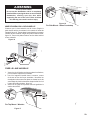
Avoiding General Hazards
Do not use the dishwasher until it is completely
installed. When opening the door on an uninstalled
dishwasher, carefully open the door while supporting
the rear of the unit. Failure to follow this warning can
cause the dishwasher to tip over and result in serious
injury.
Before installing the “L”-shaped supplied countertop
mounting brackets (select models), decide which
method will be used to secure the dishwasher into its
opening. Once these mounting brackets are installed
damage the mounting brackets and the dishwasher.
In some conditions, hydrogen gas can form in a hot
water system that has not been used for weeks.
Hydrogen gas is explosive.
been off for weeks, run the water from a nearby faucet
in a well ventilated area until there is no sound or evi-
dence of gas.
Temperatures required for soldering and sweating will
damage the dishwasher’s base and water inlet valve.
If plumbing lines are to be soldered or sweated, keep
the heat source at least 6 inches (152.4 mm) away
from the dishwasher’s base and water inlet valve.
Removing any cover or pulling the dishwasher from the
cabinet can expose hot water connections, electrical
power and sharp edges or points. Handle with care.
Avoiding Electrical Shock/Fire Hazards
Do not allow the electrical and water supply lines to
touch. Separate channels are provided under the
dishwasher.
Do not work on an energized circuit. Doing so could
-
cians should perform electrical work. Do not attempt
any work on the dishwasher electric supply circuit
until you are certain the circuit is de-energized.
should be no loose electrical connections. Ensure all
electrical connections are properly made.
The customer has the responsibility of ensuring that the
dishwasher electrical installation is in compliance with
all national and local electrical codes and ordinances.
The dishwasher is designed for an electrical supply
of 120V, 60 Hz, AC, connected to a dishwasher-
dedicated, properly grounded electrical circuit with a
fuse or breaker rated for 15 amps. Electrical supply
conductors shall be a minimum #14 AWG copper only
wire rated at 75°C (167°F) or higher.
This appliance must be connected to a grounded metal,
permanent wiring system, or an equipment-grounding
conductor must be run with the circuit conductors and
connected to the equipment-grounding terminal or
lead on the appliance. Do not use extension cords.
Avoiding Plumbing/Scalding Hazards
Do not perform any work on a charged hot water line.
perform plumbing work. Do not attempt any work on
the dishwasher hot water supply plumbing until you
are certain the hot water supply is shut off.
Do not over tighten the 90° elbow. Doing so may
damage the water inlet valve and cause a water leak.
Temperatures required for soldering and sweating will
damage the dishwasher’s water inlet valve. If plumbing
lines are to be soldered or sweated, keep the heat
source at least 6 inches (152.4 mm) away from the
dishwasher’s water inlet valve.
Check local plumbing codes for approved plumbing
procedures and accessories. All plumbing should be
done in accordance with national and local codes.
These instructions depict an installation method for
lines. If using copper tubing or other material for
water supply, defer to a licensed plumber for proper
installation.
WARNING

4
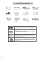
Electrical Supply Cable
ground, insulated copper conductors rated 75°C or higher.
braided dishwasher supply line.
UL listed conduit connector or strain relief is required if you attach
Hammer Hole Saw
Slot Screwdriver
T-20 Screwdriver
Wire Cutter
Wire Stripper
Drill
Level
Adjustable Wrench
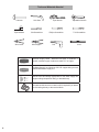
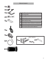
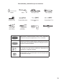
Tools and Materials Needed

5
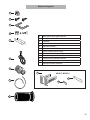
A
B
F
G
I
H
J
K
L
C
E
D
A
B
C
D
E
F
G Screw Clamp (for hose)
H Water Supply Adaptor Fitting
I
J
Rubber Drain Hose Adaptor
K
L Outer toe panel (3rd piece) Select models only
.
Materials Supplied
SELECT MODELS

6
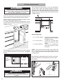
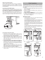
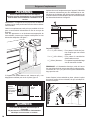
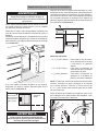
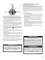
Enclosure Requirements
NOTE: T
his dishwasher is designed to be enclosed on the top
and both sides by standard residential kitchen cabinetry
.
Select a location as close to the sink as possible for easy
access to water supply and drain lines.
For proper dishwasher operation and appearance, ensure
that the enclosure is square and has the dimensions shown
in Figure 1 below.
If the dishwasher is to be installed in a corner, make sure that
there is adequate clearance to open the door. See Figure
2 below.
After locating the proper place for your new dishwasher,
you will need to make any required openings to allow for
passage of the water, drain and electrical line. In order to
avoid interference with the dishwasher when sliding it into the
cabinet, place your openings within the dimensions shown
in Figure 3 below.
Required Openings:
4
1
/
4
” x 2” (108 x 52mm) - To pass the included electrical
supply junction
box through to
an adjacent cabinet
4” x 2” (100 x 50mm) - To pass the included water
supply line toward the water
supply
1
1
/
4
” (32mm) diameter - To pass the dishwasher
drain hose toward the drain
connection
NOTE: If the incoming electric supply, water supply and
drain connections are all in the same cabinet, the one
4
1
/
4
” x 2” (108 x 52mm) hole will be large enough for all three
to pass through.
Check clearance
between
dishwasher door
and wall
Countertop
WARNING
Avoid Scalding or Electrical Shock Hazard!
Make sure the water supply and electrical supply are
shut off before installation or service.
Avoid Electrical Shock/Fire Hazard
Do not allow the electrical and water supply lines
to touch.
WARNING
4-1/2"
(114mm)
2-1/2"
(64mm)
90°
24” (61cm)
2” (5cm)
34”(86.5cm)
4”(10cm)
24”-24¼” (61-61.6 cm)
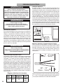
Before sliding the dishwasher into the cabinet, remove the
hose clip at the back of the dishwasher, as shown below
and discard.

7
Electrical Supply
Th
e customer has the responsibility of ensuring that the
dishwasher electrical installation is in compliance with all
national and local electrical codes and ordinances. The
dishwasher is designed for an electrical supply of 120V,
60 Hz, AC, connected to a dishwasher-dedicated, properly
grounded electrical circuit with a fuse or breaker rated for 15
amps. Electrical supply conductors shall be a minimum #14
AWG copper wire rated at 75°C (167°F) or higher.
Grounding Instructions
The dishwasher must be properly grounded before
operating. This appliance must be connected to
a grounded metal permanent wiring system, or an
equipment grounding conductor must be run with the circuit
conductors and connected to the equipment grounding
dishwasher is connected to a suitable ground in compliance
with all local codes or, in the absence of a local code, with
the NATIONAL ELECTRICAL CODE in the United States or
the CANADIAN ELECTRIC CODE C22.1-latest edition in
Canada as well as any provincial/state or municipal or local
codes that apply.
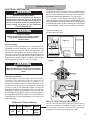
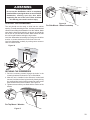
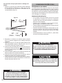
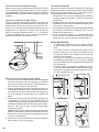
Electrical Connection
The dishwasher electrical supply junction box and ded
icated
receptacle must be mounted in an accessible cabinet
adjacent to the dishwasher (do not mount the junction box
or receptacle behind the dishwasher). You will need a
4
1
/
4
” x 2” (108 x 51mm) opening throught the cabinet in
order to
pass the junction box through (see Figure 4). If the
opening is made through wood, sand it smooth. If the opening
is made through metal, use the included protective grommet
or other approved method to protect wiring from damage.
The electrical supply can
be connected in two ways:
Method A - Three prong plug and receptacle
Use the included three-prong plug and junction box to
the household receptacle meets the electrical supply
requirements as well as national and local codes.
ELECTRICAL PREPARATION
Avoid Electrical Shock Hazard
D
o
not work on an energized circuit. Doing so
could result in serious injury or death. Only
work. Do not attempt any work on the dishwasher
electric supply circuit until you are certain the
circuit is de-energized.
Avoid Fire Hazard
Make sure electrical work is properly installed.
electrical work.
WARNING
WARNING
Avoid Fire Hazard
Ma
ke sure there are no loose electrical connections.
Make sure all electrical connections are properly
made.
WARNING
Dishwasher Electrical Rating
Volts Hertz Amperes Watts
120 60 15
1,450
(max)
12
Dedicated
Receptacle or
Field Wiring
Dishwasher
Electrical Supply
Junction Box
Electric cord with
junction box and
three prong plug
are included
with dishwasher
Figure 4
Figure 5
CLICK
Electrical Preparation
300

8
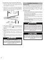
Hot Water Supply
The hot
water heater should be set to deliver approximately
120° F (49° C) water to the dishwasher. Water that is too
hot can cause some detergents to lose effectiveness. Lower
water temperatures will increase run times. The hot water
supply pressure must be between 15 - 145 psi (1 - 10 bar).
IMPORTANT NOTES:
sure to make all solder connections before connecting the
water supply line to the dishwasher.
· Always use the appropriate seal when making plumbing
connections.
· Before connecting the water supply line to the dishwasher,
to clear any foreign material.
· Turn on the water supply and check for leaks after
connections are made.
1. Remove the dishwasher electrical supply junction box
cover and connect to the power supply cord from the
house installation. (see Figure 5).
2. Remove 2” to 3” (51 - 76mm) of the outer casing of the
Figure 6.
Remove 3/8” to 1/2” (10 - 13mm) of the insulation from
each wire as shown in Figure 6.
3. Insert the bare copper or green wire(ground) to the
“G” ground connection “ “ of the terminal block
and securely tighten the terminal block screw (see
Figure 5).
4. Insert the white (neutral) wire to the “N” connection of
the terminal block and securely tighten the terminal block
screw.
5. Insert the black(hot) wire to the “L” connection of the
terminal block and securely tighten the terminal block
screw.
6. Check all electrical connections to make sure they are
secure and then attach the junction box cover with the 4
screws.
Avoid Electrical Shock Hazard
To
avoid possible injury or property damage,
care should be exercised when the dishwasher is
installed or removed to reduce the likelihood of
damage to the power cord.
WARNING
Temperatures required for soldering and sweating
will damage the dishwasher. If plumbing lines
are to be soldered or sweated, keep the heat
source at least 6 inches (152.4 mm) away from
the dishwasher.
Avoid Scald Hazard
Do not perform any work on a charged hot water
plumbers should perform plumbing work. Do not
attempt any work on the dishwasher hot water
supply plumbing until you are certain the hot water
supply is shut off.
WARNING
3/8" - 1/2"
(10mm - 13mm)
2" - 3"
(51mm - 76mm)
Figure 6
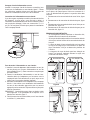
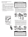
Inlet Water Connections

9
Water Supply Shut Off Valve
Install an
easily accessible shut-off valve (not supplied) in
the hot water supply line, as shown in Figure 7. All solder
connections must be made before the water line is connected
to the dishwasher.
Connecting the Hot Water Supply
There are two plastic corrugated hoses that exit the back of
end, is the water supply hose to the dishwasher (the other
hose is the dishwasher drain hose). You will need a 3” x 1
3
/
4
”
(76 x
45mm) opening through the cabinet to pass the dish-
washer water supply line through toward the shut off valve.
To connect the hot water supply:
1. Assemble the water supply adaptor fitting from the
parts bag onto the dishwasher water supply hose. This
adaptor through the opening toward the water shut off
valve. Take care not to allow the hose to kink or twist
behind the dishwasher.
3. Connect the dishwasher water supply line with adaptor to
the water shut off valve. You will need to use an approved
this connection. Always use the appropriate seal when
making plumbing connections.
NOTE: The end of the dishwasher water inlet hose is
heavy and will need to be supported. It is best to lay the
Figure 7.
4. After all connections are made, turn on the hot water and
check for leaks.
The dishwasher drain hose may be connected to the house-
a 1
1
/
4
” diameter hole in order to pass the drain hose through
the cabinet.
1 D
irectly to the undersink dishwasher drain connection, as
shown in Figure 8.
2 Directly to a disposer dishwasher drain connection, as
shown in Figure 9.
3 To the undersink dishwasher drain connection through an
air gap, as shown in Figure 10.
4 To a disposer dishwasher drain connection through an air
gap, as shown on Figure 11.
IMPORTANT NOTES:
· If local ordinance require an air gap, install it according
to the manufacturer’
s instructions.
· If the dishwasher drain hose is to be connected to a
disposer dishwasher drain connection, remove the plug
from the disposer’s dishwasher drain connection.
· The dishwasher drain hose must have one place along
its length that is securely attached 20 inches above the
· The drain hose length can be extended if necessary. The
maximum length of the drain hose, including the hose
leading to the air gap, is 150 inches.
Dishwasher
Water Inlet
Hose
Water
Shut Off
Va lve
110-120V
Figure 7
Figure 10 Figure 11
Figure 8
Non-Metallic Tie
MIN.
20"
MIN.
20"
Non-Metallic Tie
Figure 9
Remove
plug
Drain Connections

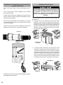
10
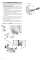
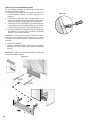
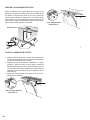
The dishwasher can be secured into its enclosure in two
ways:
T
op
Mount1. is used for countertops made of wood or
other materials that can easily drilled. Orient the mount-
ing brackets as shown in Figure 14, and position the two
small tabs on the mounting brackets over the two slots
Side Mount1. is used for countertops made of marble,
granite, or other very hard materials that cannot be easily
drilled. Bend the mounting brackets along the small
holes and in the same direction as the two small tabs.
Orient the mounting brackets as shown in Figure 15, and
position the two small tabs on the mounting brackets
over the two slots on the dishwasher’s front corners.
tabs into the slots.
For a large port, use the drain hose as it is.
For a
small port, insert the rubber drain hose adaptor 1.
into the drain hose end.
Obtain the Rubber Drain Hose Adaptor spring clamp from 2.
the Dishwasher Installation Kit (do not substitute).
Insert the dishwasher drain hose into the 3. end of the
drain hose (see Figure 12). Be sure to fully insert the
drain hose.
Use the clamp provided to attach the Rubber Drain Hose 4.
Adaptor to the house plumbing
Figure 13
Figure 12
Before installing
the supplied countertop mounting
brackets, decide which method of securing the
dishwasher into its enclosure will be used. Once the
mounting brackets are installed on the dishwasher,
removing them is difficult and will damage the
mounting brackets and the dishwasher.
Figure 15
Screw
Clamp
Installation of Mounting BracketsInstallation of Rubber Drain Hose Adaptor
Top Mount
Figure 14
Side Mount

11
The unit should now be ready to slide into the cabin
e
t
sure that the hoses and cords do not bunch up behind the
the unit into place before raising the leg levelers.
Level the dishwasher horizontally by turning feet clockwise
to raise or counter-clockwise to lower front of the unit.
Level the dishwasher vertically by turning center screw to
raise or lower the back.
1. Drive the mounting screws through the holes in the
2. After the unit is installed in the enclosure, leveled and
secured, lock the two front leg levelers in place by driving
the enclosed leg leveler locking screws into each screw
boss located in front of the levelers. See Figure 18.
bosses.
LEVELING THE DISHWASHER
SECURING THE DISHWASHER
For Top Mount - Wooden
For Side Mount - Stone Countertop
Avoid Tip Over Hazard
Do not
use the dishwasher until it is completely
installed. When opening the door on an uninstalled
dishwasher, carefully open the door while
supporting the rear of the unit. Failure to follow
this warning can result in serious injury.
WARNING
Figure 16
Figure 17
Figure 18
0- 2.5 “
mm/ 0.5”
mm/ 0.1”
mm/ 0.1”
mm/ 0.5”

12
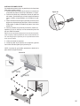
Your dishwasher comes with a three-piece toe panel(select
models) to allow height adjustment.
panel allowing the angled edge to rest on the mating edge
of the dishwasher.
3. Drive the two black screws (included) through the hole in
the toe panel to secure. Use the supplied screws to avoid
damaging the dishwasher. See Figure 19.
4. For models with outer toe panel (3rd piece) slide the
brackets (A) provided, into the slots of the toe panel you
just attached.
NOTE: Once you determine the correct position for the brackets ,
remove the
bracket and bend the metal tab. See Figure 20. This
ensures that the toe panel wont slide in further than you need.
5. Re-insert the brackets.
6.
Attach the outer toe panel (L) onto the brackets and drive
the screws provided in place to secure the toe panel.
NOTE: The rubber piece should remain behind the outer
toe panel.
Figure 19
A
Figure 20
Attaching the Toe Panel
(K)

13
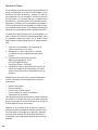
Your dishwasher requires no special care other than
with your dishwasher, before calling for service please
refer to the Self Help section in the Use and Care
installer or an authorized service center.
Do not attempt to repair the appliance yourself. Any
work performed by unauthorized personnel may void
the warranty. If you are having a problem with your
dishwasher and are not pleased with the service you
have received, please take the following steps (in the
order listed below) until the problem is corrected to
your satisfaction:
Contact your installer or the Authorized Service 1.
Contractor in your area.
2.
instructions.
Write us at the address below:3.
BSH Home Appliances, Corp.
Huntington Beach, CA 92649
Call us at the Customer Service phone number :4.
1-800-944-2904
available (if you are calling), the following information:
manual. The customer must show proof of purchase to
obtain warranty service.
Customer Service
Page is loading ...
Page is loading ...
Page is loading ...
Page is loading ...
Page is loading ...
Page is loading ...
Page is loading ...
Page is loading ...
Page is loading ...

23
MISE DE NIVEAU DU LAVE-VAISSELLE
le lave-vaisselle.
1.
2.
deuxpieds niveleurs avant en place en vissant les vis de
3.
surface des reliefs.
FIXER LE LAVE-VAISSELLE
For Top Mount - Wooden
For Side Mount - Stone Countertop
Avoid Tip Over Hazard
Do not
use the dishwasher until it is completely
installed. When opening the door on an uninstalled
dishwasher, carefully open the door while
supporting the rear of the unit. Failure to follow
this warning can result in serious injury.
WARNING
Figure 16
Figure 17
Figure 18
0- 2.5 “
mm/ 0.5”
mm/ 0.1”
mm/ 0.1”
mm/ 0.5”
Page is loading ...
Page is loading ...
Page is loading ...
Page is loading ...
Page is loading ...
Page is loading ...
Page is loading ...
Page is loading ...
Page is loading ...
Page is loading ...
Page is loading ...
Page is loading ...
Page is loading ...
Page is loading ...
Page is loading ...
Page is loading ...
-
 1
1
-
 2
2
-
 3
3
-
 4
4
-
 5
5
-
 6
6
-
 7
7
-
 8
8
-
 9
9
-
 10
10
-
 11
11
-
 12
12
-
 13
13
-
 14
14
-
 15
15
-
 16
16
-
 17
17
-
 18
18
-
 19
19
-
 20
20
-
 21
21
-
 22
22
-
 23
23
-
 24
24
-
 25
25
-
 26
26
-
 27
27
-
 28
28
-
 29
29
-
 30
30
-
 31
31
-
 32
32
-
 33
33
-
 34
34
-
 35
35
-
 36
36
-
 37
37
-
 38
38
-
 39
39


Ask a question and I''ll find the answer in the document
Finding information in a document is now easier with AI
in other languages
- français: Bosch SGE63E06UC/25 Guide d'installation
- español: Bosch SGE63E06UC/25 Guía de instalación
Related papers
-
Bosch SHE68TL5UC Installation guide
-
-
-
Bosch SHXM78W54N Installation guide
-
Bosch SHE6AP05UC/02 Installation guide
-
Bosch SHXM78W54N Installation guide
-
Yes SPE53B56UC Installation guide
-
Bosch SHE3ARF5UC/06 Installation guide
-
Yes SPX68B55UC Installation guide
-
Other documents
-
Gaggenau DF 480 700F Installation guide
-
Gaggenau 400 Series Top Control Built In Dishwasher User manual
-
Thermador DWHD440MFP/02 Installation guide
-
-
Costco SMZPCJB1UC Junction Box User manual
-
-
Thermador DWHD770WFM Installation guide
-
-
Maytag Dishwasher Installation Instructions Manual
-