10
ENG
ENGLISH
ASSEMBLING AND PREPARING
y
Disconnect the power cord first, and then
move or install the Monitor set. Otherwise
electric shock may occur.
y
If you install the Monitor set on a ceiling or
slanted wall, it may fall and result in severe
injury. Use an authorized LG wall mount
and contact the local dealer or qualified
personnel.
y
Do not over tighten the screws as this may
cause damage to the Monitor set and void
your warranty.
y
Use the screws and wall mounts that
meet the VESA standard. Any damages
or injuries by misuse or using an improper
accessory are not covered by the warranty.
y
Use the screws that are listed on the VESA
standard screw specifications.
y
The wall mount kit includes an installation
manual and necessary parts.
y
The wall mount bracket is optional. You can
obtain additional accessories from your local
dealer.
y
The length of screws may differ depending
on the wall mount. Be sure to use the proper
length.
y
For more information, refer to the
instructions supplied with the wall mount.
CAUTION
NOTE
NOTE
y
Do not install the product in a place with
no ventilation (e.g., on a bookshelf or in a
closet) or on a carpet or cushion. If there is
no other option but to mount the product on
the wall, make sure that sufficient ventilation
is provided before installation.
- Failure to do so may result in a fire due to
the increase in the internal temperature.
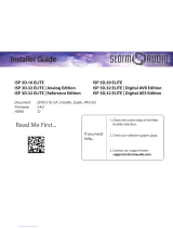
If you want to mount the monitor on the wall (op-
tional), attach the wall mounting bracket to the rear
of the monitor.
Make sure that the wall mounting bracket is se-
curely fixed to the monitor and to the wall.
Use the wall mount plate and screws that comply
with the VESA standard.
Use the wall mount plate and screws conforming
to the VESA standard.
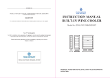
Installing on a wall
Install the monitor at least 10 cm away from the
wall and leave about 10 cm of space at each side
of the monitor to ensure sufficient ventilation. De-
tailed installation instructions can be obtained from
your local retail store. Please refer to the manual
to install and set up a tilting wall mounting bracket.
10 cm
10 cm
10 cm
10 cm
20 cm