Page is loading ...

#838 • 8/07
W 1 6 4 N 9 2 2 1 Wa ter Str ee t • P.O. Box 450 • Menomonee Falls, Wisconsin 53052-0450 USA
PHONE: 262.251.3800 • 800.558.8744
USA/CANADA FAX: 262.251.7067 • 800.329.8744 U.S.A. ONLY
WEBSITE: www.alto-shaam.com
P R I N T E D I N U .S .A .
®
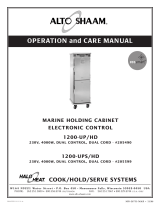
F o o d H o l d i n g C a b i n e t
E l e c t r i c
Models:
1000-UP
1200-UP
Manual Control
• INSTALLATION
• OPERATION
• MAINTENANCE
1000-UP/HD
1200-UP/HD

# 8 3 8 • I N STA L L A T I O N / O P E R A T I O N / SERV I C E M A N UA L • 1.
DELIVERY
This Alto-Shaam appliance has been
thoroughly tested and inspected to insure only the
highest quality unit is provided. Upon receipt,
check for any possible shipping damage and
report it at once to the delivering carrier. See
Transportation Damage and Claims section
located in this manual.
This appliance, complete with unattached
items and accessories, may have been delivered in
one or more packages. Check to ensure that all
standard items and options have been received
with each model as ordered.
Save all the information and instructions
packed with the appliance. Complete and return
the warranty card to the factory as soon as
possible to assure prompt service in the event of a
warranty parts and labor claim.
This manual must be read and understood by
all people using or installing the equipment
model. Contact the Alto-Shaam service
department if you have any questions concerning
installation, operation, or maintenance.
NOTE: All claims for warranty must include the
full model number and serial number of
the unit.
UNPACKING
1. Carefully remove the
appliance from the
carton or crate.
NOTE: Do not discard the
carton and other
packaging material
until you have
inspected the unit
for hidden damage
and tested it for
proper operation.
2. Read all instructions in this manual carefully
before initiating the installation of this appliance.
DO NOT DISCARD THIS MANUAL.
This manual is considered to be part of the
appliance and is to be provided to the owner
or manager of the business or to the person
responsible for training operators. Additional
manuals are available from the Alto-Shaam
service department.
3. Remove all protective plastic film, packaging
materials, and accessories from the appliance
before connecting electrical power. Store any
accessories in a convenient place for future use.
®
®
®

# 8 3 8 • I N STA L L A T I O N / O P E R A T IO N / SE RV I C E M A N U A L • 2.
SAFETY PROCEDURES
AND PRECAUTIONS
Knowledge of proper procedures is essential to the
safe operation of electrically and/or gas energized
equipment. In accordance with generally accepted
product safety labeling guidelines for potential
hazards, the following signal words and symbols
may be used throughout this manual.
Used to indicate the
presence of a hazard that
will
cause severe personal
injury, death, or substantial
property damage if the
warning included with this
symbol is ignored.
Used to indicate the
presence of a hazard that
can
cause personal injury,
possible death, or major
property damage if the
warning included with this
symbol is ignored.
Used to indicate the
presence of a hazard that
can or will cause minor or
moderate personal injury
or property damage if the
warning included with this
symbol is ignored.
Used to indicate the
presence of a hazard that
can or will cause minor
personal injury, property
damage, or a potential
unsafe practice if the
warning included with this
symbol is ignored.
Used to notify personnel of
installation, operation, or
maintenance information that is
important but not hazard related.
1. This appliance is intended to cook, hold or
process foods for the purpose of human
consumption. No other use for this
appliance is authorized or recommended.
2. This appliance is intended for use in
commercial establishments where all
operators are familiar with the purpose,
limitations, and associated hazards of this
appliance. Operating instructions and
warnings must be read and understood by
all operators and users.
3. Any troubleshooting guides, component
views, and parts lists included in this manual
are for general reference only and are intended
for use by qualified technical personnel.
4. This manual should be considered a
permanent part of this appliance. This
manual and all supplied instructions,
diagrams, schematics, parts lists, notices, and
labels must remain with the appliance if the
item is sold or moved to another location.
NOTE:

# 8 3 8 • I N STA L L A T I O N / O P E R A T I O N / SE RV I C E M A N U A L • 3.
I N S T A L L A T I O N
S I T E I N S T A L L A T I O N
C L E A R A N C E R E Q U I R E M E N T S
3-inches (76mm) at the back, 2-inches (51mm) at the top,
1-inch (25mm) at both sides
W E I G H T
1000-UP/STD 1000-UP/HD
NET 241 lb (109 kg) 270 lb (122kg)
SHIP 275 lb (125kg) 303 lb (137kg)
CARTON
DIMENSIONS
:
80" x 30" x 37"
(2032mm x 762mm x 940mm)
H x W x D (EST.)
85" x 30" x 37"
(2159mm x 762mm x 940mm)
H x W x D (EST.)
TO PREVENT PERSONAL INJURY,
USE CAUTION WHEN MOVING OR
LEVELING THIS APPLIANCE.
W E I G H T
1200-UP/STD 1200-UP/HD
NET 276 lb (125kg) 301 lb (137kg)
SHIP 315 lb (142kg) 350 lb (159kg)
CARTON
DIMENSIONS
:
1. This appliance is designed for the purpose of
maintaining hot food at a temperature for
safe consumption. The unit must be
installed on a level surface in a location that
will permit the equipment to function for its
intended purpose and allow adequate access
for proper cleaning and maintenance.
2. The appliance must not be installed in any
area where it will be affected by steam,
grease, dripping water, high temperatures, or
any other severely adverse conditions.
3. Level the appliance from side-to-side and
front-to-back using a spirit level.
4. In order to maintain standards established
by the National Sanitation Foundation, all
equipment must be equipped with casters or
6" (152mm) legs to provide minimum
unobstructed space beneath the unit; or
secured flush at the bottom and the entire
base sealed with NSF approved sealant.
Warranty will become null and void if these
directions are
not followed.

# 8 3 8 • I N STA L L A T I O N / O P E R A T I O N / SE RV I C E M A N U A L • 4.
I N S T A L L A T I O N
E X T E R I O R D I M E N S I O N S
75-11/16" (1922mm)
73-1/16" (1855mm)
7" (177mm)
30-1/2" (774mm)
26-1/2" (673mm)
3-5/16"
(84mm)
13-15/16"
(353mm)
71-7/16" (1813mm)
49-5/8" (1260mm)
33-7/8" (860mm)
with bumper
22-5/8" (573mm)
2
5-1/16"
(
636mm)
w
ith bumper
electrical
pass-thru
1000-UP
O P T I O N S & A C C E S S O R I E S
Bumper, FULL PERIMETER 5005103
Casters, 3-1/2" (89mm)
2 RIGID, CS-25674
Casters, 3-1/2" (89mm) 2 SWIVEL W/BRAKE CS-25675
Door Lock with Key LK-22567
HACCP Network Options (
ELECTRONIC CONTROL ONLY)
REFER TO SPECIFICATION #9015 FOR APPLICABLE PART NUMBERS
➥ HACCP Documentation
➥ HACCP with Kitchen Management
Legs, 6" (152mm) Flanged (SET OF FOUR) 5004863
Pan Grid, Wire, chrome plated PN-2115
➥ PAN INSERT 18" x 26" (457mm x 660mm x 25mm)
Probe, Internal Temperature (ELECTRONIC CONTROL) AVAILABLE
Shelf, Stainless Steel, REACH-IN SH-2325
Shelf, Stainless Steel, PASS-THROUGH SH-2346
Water Reservoir Pan
(INCLUDED WITH PROOFING CABINET) 1775
Water Reservoir Pan Cover* 1774

# 8 3 8 • I N STA L L A T I O N / O P E R A T I O N / SE RV I C E M A N U A L • 5.
75-11/16" (1922mm)
72-7/8" (1851mm)
6-13/16" (172mm)
78-3/4" (2000mm)
26" (659mm)
30-1/2" (773mm)
26-1/2" (672mm)
3-5/16" (83mm)
53-5/16" (1353mm)
33-7/8" (860mm)
with bumper
electrical
pass-thru
2
8-3/16"
(
716mm)
w
ith bumper
1200-UP
I N S T A L L A T I O N
E X T E R I O R D I M E N S I O N S
O P T I O N S & A C C E S S O R I E S
Bumper, FULL PERIMETER 5004861
Casters, 3-1/2" (89mm)
2 RIGID, CS-25674
Casters, 3-1/2" (89mm) 2 SWIVEL W/BRAKE CS-25675
Door Lock with Key LK-22567
HACCP Network Options (
ELECTRONIC CONTROL ONLY)
REFER TO SPECIFICATION #9015 FOR APPLICABLE PART NUMBERS
➥ HACCP Documentation
➥ HACCP with Kitchen Management
Legs, 6" (152mm) Flanged (SET OF FOUR) 5004863
Pan Grid, chrome plated, wire PN-2115
➥
PAN INSERT 18" x 26" (457mm x 660mm x 25mm)
Probe, Internal Temperature (ELECTRONIC CONTROL) AVAILABLE
Universal Angle Configuration
➥ Pan Slides, Chrome Plated SR-24447
➥ Pan Slides, Stainless Steel SR-24762
Side Rack Configuration
➥ Side Rack, Chrome Plated SR-22445
➥ Side Rack, Stainless Steel SR-23739
➥ Shelf, Stainless Steel SH-23738
➥ Shelf, Chrome Plated SH-2733
Water Reservoir Pan 1775
Water Reservoir Pan Cover 1774

# 8 3 8 • I N STA L L A T I O N / O P E R A T I O N / SE RV I C E M A N U A L • 6.
I N S T A L L A T I O N
E L E C T R I C A L I N S T A L L A T I O N
1. An identification tag is permanently mounted on
the cabinet.
2. Plug cabinet into a properly grounded receptacle
ONLY, positioning the unit so the power supply
cord is easily accessible in case of an emergency.
Arcing will occur when connecting or disconnecting
the unit unless all controls are in the “OFF” position.
3. If necessary, a proper receptacle or outlet
configuration as required for this unit, must be
installed by a licensed electrician in accordance with
applicable, local electrical codes.
For 230V:
To prevent an electrical shock hazard between the
appliance and other appliances or metal parts in
close vicinity, an equalization-bonding stud is
provided. An equalization bonding lead must be
connected to this stud and the other appliances /
metal parts to provide sufficient protection against
potential difference. The terminal is marked with the
following symbol.
NOTE:
The appliance must be connected to an electrical
circuit that is protected by an external GFCI outlet.
(
USA ONLY)
120
208
240
230
ELECTRICAL • 1000-UP
VOLTAGE PHASE CYCLE
/
HZ AMPS
kW
at 120 1 60 16.0 2.0 NEMA
5-20
P
, 20A-125
V PLUG
at 208 1 50/60 7.2 1.5
NEMA
6-15
P
, 15A-250
V PLUG
at 240 1 50/60 8.3 2.0
at 230 1 50 7.8 1.8
CEE 7/7, 220-230V PLUG
230
208 - 240
120
ELECTRICAL • 1200-UP
VOLTAGE PHASE CYCLE
/
HZ AMPS
kW
at 120 1 60 16.0 2.0
at 208 1 50/60 7.2 1.5
at 240 1 50/60 8.3 2.0
at 208 1 50/60 14.4 3.0
at 240 1 50/60 16.0 4.0
at 230 1 50 7.8 1.8
NEMA 5-15P,
20A-125V PLUG
NEMA
6-15
P
,
15A-250
V PLUG
(USA ONLY)
CEE
7/7,
220-230
V PLUG
NO CORD
NO PLUG

This appliance is intended for use in commercial
establishments where all operators are familiar with the
purpose, limitations, and associated hazards of this
appliance. Operating instructions and warnings must
be read and understood by all operators and users.
1. Check that the unit is connected to the appropriate
power source.
2. Use hand protection when handling hot items.
3. Preheat the unit for 30 minutes before use.
4. Be certain only hot foods are placed into the unit.
BEFORE INITIAL USE:
1. Clean both the interior and exterior of the unit
with a damp, clean cloth and mild soap solution.
Rinse carefully.
2. Clean and install the cabinet side racks. Shelves
should be positioned with the curved end up and
toward the back of the unit (reach-in models).
HEATING CHARACTERISTICS
The cabinet is equipped with a special heating cable.
Through this Halo Heat concept, the heating cable is
mounted against the walls of the unit to provide an
evenly applied heat source controlled by a thermostat.
The design and operational characteristics of the unit
eliminate the need for a moisture pan or a heat
circulating fan. Through even heat application, the
quality of food products is maintained up to several
hours or more.
With the addition of a pan of water, warming
cabinets can be used for proofing dough. A water
reservoir pan (#1775) and pan cover (#1774) are
available from Alto-Shaam.
1. Remove dough from retarder or refrigerator, and
allow covered product to set up at room
temperature.
2. Set holding thermostat to 95°F (35°C).
3. Pour approximately 2 quarts (c. 2 liters) of hot
water, 140-180°F (60-82°C) into a pan on the
bottom surface of the holding compartment.
4. Preheat cabinet for 45-60 minutes.
5. Remove covering and place product in preheated
cabinet.
6. Allow dough to remain in the cabinet until it
approximately doubles in size.
7. Remove product from cabinet, and bake according
to product manufacturer's directions. Brush with
eggwash if desired.
NOTE: The above proofing procedure is suggested as
a general guideline only. Due to variations in
product, product quality, and weight,
adherence to the product manufacturer's
instructions are recommended.
# 8 3 8 • I N STA L L A T I O N / O P E R A T I O N / SE RV I C E M A N U A L • 7.
I N S T A L L A T I O N
USER SAFETY INFORMATION PROCEDURE FOR PROOFING DOUGH
C A PA C I T Y • 1 0 0 0 - U P (P E R CO M PA RT M E N T )
120 lbs (54kg) MAXIMUM
VOLUME MAXIMUM: 60 QTS (76 LITERS)
FULL-SIZE PANS: GASTRONORM 1/ 1:
Eight (8) 20" x 12" x 2-1/2" 530mm x 325mm x 65mm
FULL-SIZE SHEET PANS: (WITH SHELVES)
Eight (8) 18" x 26" x 1"
C A PA C I T Y • 1 2 0 0 - U P (P E R CO M PA RT M E N T )
192 lbs (87kg) MAXIMUM
VOLUME MAXIMUM: 120 QUARTS (152 LITERS)
—WITH PAN SLIDES PROVIDED:—WITH ADDT'L PAN SLIDES:
FULL-SIZE PANS: GASTRONORM 1/ 1:
Eight (8) 20" x 12" x 2-1/2" (530mm x 325mm x 65mm) up to 16 Pans
Eight (8) 20" x 12" x 4" (530mm x 325mm x 100mm) up to 10 Pans
Eight (8) 20" x 12" x 6" (530mm x 325mm x 150mm)
FULL-SIZE SHEET PANS:
Four (4) 18" x 26" x 1" up to 16 Pans
UNIVERSAL PAN SLIDES - 1-3/4" (44mm) CENTERS w ith ad d itio nal sh e lve s
—WITH OPTIONAL SIDE RACKS FOR SHELVES
FULL
-SIZE PANS: GASTRONORM 1/ 1:
Sixteen (16) 20" x 12" x 2-1/2" (530mm x 325mm x 65mm)
Ten (10) 20" x 12" x 4" (530mm x 325mm x 100mm)
Eight (8) 20" x 12" x 6" (530mm x 325mm x 150mm)

# 8 3 8 • I N STA L L A T I O N / O P E R A T I O N / SE RV I C E M A N U A L • 8.
O P E R A T I O N
M A N U A L C O N T R O L
1. Preheat at 200°F (93°C) for 30 minutes.
Press the ON key. The ON key will illuminate. Turn
t
he thermostat clockwise. The indicator light will
illuminate and will remain lit as long as the unit
is calling for heat. Allow a minimum of 30
minutes of preheating before loading the holding
cabinet with food. Closing the vents on the inside
of the door will speed up the process. The
indicator light will go OUT after approximately
30 minutes, or when the air temperature inside the
unit reaches the temperature set by the operator.
2. Load the cabinet with hot food only.
The purpose of the holding cabinet is to
maintain hot food at proper serving temperatures.
Only hot food should be placed into the cabinet.
Before loading the unit with food, use a food
thermometer to make certain all food products are
at an internal temperature range of 140° to 160°F
(60° to 71°C). All food not within the proper
temperature range should be heated before
loading into the holding cabinet.
3. Reset the thermostat to 160°F (71°C).
Check to make certain the cabinet door is securely
closed, and reset the thermostat to 160°F (71°C).
THIS WILL NOT
NECESSARILY BE THE
FINAL SETTING.
The proper temperature range for the food being
held will depend on the type and quantity of
product. Whether or not the door vents should
be open or closed will also depend on the type of
food being held. When holding food for
prolonged periods, it is advisable to periodically
check the internal temperature of each item to
assure maintenance of the proper temperature
range.
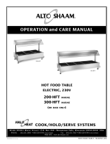
Heat
Indicator
Light
Thermostat
ON/OFF
TOP CONTROLSBOTTOM CONTROLS
1000-UP
1200-UP
Temperature
Gauge

# 8 3 8 • I N STA L L A T I O N / O P E R A T I O N / SE RV I C E M A N U A L • 9.
O P E R A T I O N
Chefs, cooks and other specialized food service
personnel employ varied methods of cooking. Proper
h
olding temperatures for a specific food product
must be based on the moisture content of the
product, product density, volume, and proper serving
temperatures. Safe holding temperatures must also
be correlated with palatability in determining the
length of holding time for a specific product.
Halo Heat maintains the maximum amount of
product moisture content without the addition of
water, water vapor, or steam. Maintaining maximum
natural product moisture preserves the natural flavor
of the product and provides a more genuine taste.
In addition to product moisture retention, the gentle
properties of Halo Heat maintain a consistent
temperature throughout the cabinet without the
necessity of a heat distribution fan, thereby
preventing further moisture loss due to evaporation
or dehydration.
When product is removed from a high temperature
cooking environment for immediate transfer into
equipment with the lower temperature required for
hot food holding, condensation can form on the
outside of the product and on the inside of plastic
containers used in self-service applications.
Allowing the product to release the initial steam
and heat produced by high temperature cooking
can alleviate this condition. To preserve the safety
and quality of freshly cooked foods however, a
maximum of 1 to 2 minutes must be the only time
period allowed for the initial heat to be released
from the product.
Most Halo Heat holding equipment is provided
with a thermostat control between 60° and 200°F
(16° to 93°C). If the unit is equipped with vents,
close the vents for moist holding and open the vents
for crisp holding.
If the unit is equipped with a thermostat indicating
a range of between 1 and 10,use a metal-stemmed
indicating thermometer to measure the internal
temperature of the product(s) being held. Adjust the
thermostat setting to achieve the best overall setting
based on internal product temperature.
H
O L D I N G T E MP E R AT U R E R A N G E
MEAT FAHRENHEIT CELSIUS
B
EEF ROAST — Rare 140°F 60°C
BEEF ROAST — Med/Well Done 160°F 71°C
B
EEF BRISKET 160° — 175°F 71° — 79°C
C
ORN BEEF 160° — 175°F 71° — 79°C
PASTRAMI 160° — 175°F 71° — 79°C
P
RIME RIB — Rare 140°F 60°C
STEAKS — Broiled/Fried 140° — 160°F 60° — 71°C
R
IBS — Beef or Pork 160°F 71°C
VEAL 160° — 175°F 71° — 79°C
HAM 160° — 175°F 71° — 79°C
PORK 160° — 175°F 71° — 79°C
L
AMB 160° — 175°F 71° — 79°C
POULTRY
C
HICKEN — Fried/Baked 160° — 175°F 71° — 79°C
DUCK 160° — 175°F 71° — 79°C
TURKEY 160° — 175°F 71° — 79°C
GENERAL 160° — 175°F 71° — 79°C
FISH/ SEAFOOD
FISH — Baked/Fried 160° — 175°F 71° — 79°C
LOBSTER 160° — 175°F 71° — 79°C
SHRIMP — Fried 160° — 175°F 71° — 79°C
BAKED GOODS
BREADS/ROLLS 120° — 140°F 49° — 60°C
MISCELLANEOUS
CASSEROLES 160° — 175°F 71° — 79°C
DOUGH — Proofing 80° — 100°F 27° — 38°C
EGGS —Fried 150° — 160°F 66° — 71°C
FROZEN ENTREES 160° — 175°F 71° — 79°C
HORS D'OEUVRES 160° — 180°F 71° — 82°C
PASTA 160° — 180°F 71° — 82°C
PIZZA 160° — 180°F 71° — 82°C
POTATOES 180°F 82°C
PLATED MEALS 180°F 82°C
SAUCES 140° — 200°F 60° — 93°C
SOUP 140° — 200°F 60° — 93°C
VEGETABLES 160° — 175°F 71° — 79°C
T h e h o l d i n g t e m p e r a t u r e s l i s t e d a r e s u g g e s t e d g u i d e l i n e s o n l y.
G E N E R A L H O L D I N G G U I D E L I N E S

# 8 3 8 • I N STA L L A T I O N / O P E R A T I O N / SE RV I C E M A N U A L • 10.
PROTECTING STAINLESS STEEL SURFACES
It is important to guard against
corrosion in the care of
stainless steel surfaces.
Harsh, corrosive, or
inappropriate chemicals can
completely destroy the
protective surface layer of stainless steel. Abrasive
pads, steel wool, or metal implements will abrade
surfaces causing damage to this protective coating
and will eventually result in areas of corrosion.
Even water, particularly hard water that contains
high to moderate concentrations of chloride, will
cause oxidation and pitting that result in rust and
corrosion. In addition, many acidic foods spilled
and left to remain on metal surfaces are
contributing factors that will corrode surfaces.
Proper cleaning agents, materials, and
methods are vital to maintaining the appearance
and life of this appliance. Spilled foods should be
removed and the area wiped as soon as possible
but at the very least, a minimum of once a day.
Always thoroughly rinse surfaces after using a
cleaning agent and wipe standing water as quickly
as possible after rinsing.
CLEANING AGENTS
U
se non-abrasive cleaning products designed for use
on stainless steel surfaces. Cleaning agents must be
chloride-free compounds and must not contain
quaternary salts. Never use hydrochloric acid
(muriatic acid) on stainless steel surfaces. Always use
the proper cleaning agent at the manufacturer's
recommended strength. Contact your local cleaning
supplier for product recommendations.
CLEANING MATERIALS
The cleaning function can usually be accomplished
with the proper cleaning agent and a soft, clean
cloth. When more aggressive methods must be
employed, use a non-abrasive scouring pad on
difficult areas and make certain to scrub with the
visible grain of surface metal to avoid surface
scratches. Never use wire brushes, metal scouring
pads, or scrapers to remove food residue.
CLEANING AND PREVENTIVE MAINTENANCE
C A R E a n d C L E A N I N G

# 8 3 8 • I N STA L L A T I O N / O P E R A T I O N / SE RV I C E M A N U A L • 11.
1. Disconnect unit from power source, and let cool.
2. Remove all detachable items such as shelves, side
racks, and drip pan. Clean these items separately
with a good grease solvent or commercial detergent.
Rinse well and dry.
3. Clean interior metal surfaces of the unit with a
damp, clean cloth and any good commercial
detergent or grease solvent at the recommended
strength. Spray heavily
soiled areas with a
water soluble degreaser
and let stand for 10
minutes, then remove
soil with a plastic
scouring pad. Rinse by
wiping with a sponge
and clean warm water
to remove all residue.
Remove excess water
with sponge and wipe dry with a clean cloth or air
dry. Replace side racks and shelves.
NOTE: Avoid the use of abrasive cleaning,
compounds, chloride based cleaners,
or cleaners containing quaternary salts.
Never use hydrochloric acid (muriatic acid)
on stainless steel.
4. Clean control panel, door vents, door handles, and
door gaskets thoroughly since these areas harbor
food debris. Rinse by wiping with sponge and
clean warm water. Wipe dry with a clean cloth.
5. Interior can be wiped with a sanitizing solution
after cleaning and rinsing. This solution must
be approved for use on stainless steel food
contact surfaces.
6. To help maintain the protective film coating on
polished stainless steel, clean the exterior of the unit
with a cleaner recommended for stainless steel
surfaces. Spray the cleaning agent on a clean cloth
and wipe with the grain of the stainless steel.
7. Clean any glass with window cleaner.
Always follow appropriate state or local health
(hygiene) regulations regarding all applicable
cleaning and sanitation requirements for foodservice
equipment.
The cleanliness and appearance of this unit will contribute
c
onsiderably to operating efficiency and savory, appetizing food.
Good equipment kept clean works better and lasts longer.
THOROUGHLY CLEAN THE UNIT DAILY
C A R E a n d C L E A N I N G

# 8 3 8 • I N STA L L A T I O N / O P E R A T I O N / SE RV I C E M A N U A L • 12.
S E R V I C E P A R T S - M A N U A L C O N T R O L
S E R V I C E
Bonnet Assembly
5005606
Casing Back
1004988
Casters, 5" rigid
CS-24874
Casters, 5" swivel w/brake
CS-24875
Control Panel
Bezel
PE-26567
Control Panel
Overlay
PE-26875
Door Assembly
15147
Door Gasket
GS-22952
Door Handle
HD-27080
Door Hinge
HG-2535
Side Panels
1004985
Side Rack
SR-2120
Temperature
Gauge
G
U-34198
Thermostat
Knob
KN-26568
1000-UP

# 8 3 8 • I N STA L L A T I O N / O P E R A T I O N / SE RV I C E M A N U A L • 13.
S E R V I C E P A R T S - M A N U A L C O N T R O L
Description 1000-UP 1200-UP
Bonnet Assembly 5005606 5005046
Bottom Assembly 1003680 1006332
Casing Back, heavy duty, top 1007439 1007474
Casing Back, heavy duty, bottom 1006697 1006704
Casing Back, standard 1004988 1006711
Casters, 5" (127mm) rigid (each) CS-24874 CS-24874
Casters, 5" (127mm) swivel w/brake (each) CS-24875 CS-24875
Control Panel, Bezel PE-26567 PE-27268
Control Panel, Overlay, Manual PE-26875 PE-27995
Door Assembly, slab 15147 5005140
Door Gasket, ea. GS-22952 GS-23796
Door Handle HD-27080 HD-27080
Door Hinge, ea. HG-2535 HG-22338
Side Panels, heavy duty 1003742 1006716
Side Panels, standard 1004985 1006714
Side Rack SR-2120 SR-24447
Temperature Gauge GU-34198 GU-34198
Thermostat Knob, Manual KN-26568 KN-26568
Electrical
Cordset, 125V CD-33824 CD-33824
Cordset, 208/240V CD-3551 CD-3551
Cordset, 230V CD-3922 CD-3922
Indicator Light, 125V LI-3027 LI-3027
Indicator Light, 208/240V & 230V LI-3951 LI-3951
Line Filter, 230V only FI-33225 FI-33225
Switch, Rocker, 125V SW-34375 SW-34375
Switch, Rocker, 208V & 230V SW-34351 SW-34351
Terminal Block BK-3019 BK-3019
Thermostat, Manual TT-3057 TT-33432
S E R V I C E
includes:
CB-3044 Cable Heating Element . .108 feet
CR-3226 Ring Connector . . . . . . . . . . . . . .4
IN-3488 Insulation Corner . . . . . . . .1 foot
BU-3105 Shoulder Bushing . . . . . . . . . . . .4
BU-3106 Cup Bushing . . . . . . . . . . . . . . . .4
ST-2439 Stud . . . . . . . . . . . . . . . . . . . . . . .4
NU-2215 Hex Nut . . . . . . . . . . . . . . . . . . . .8
SL-3063 Insulating Sleeve . . . . . . . . . . . . .4
TA-3540 Electrical Tape . . . . . . . . . . .1 roll
C A B L E H E AT I N G S E R V I C E
K I T No. 4874
1000-UP
No. 4878 for all except 4000W cabinets
INCLUDES:
CB-3045 Cable Heating Element . . . . .85 feet)
CR-3226 Ring Connector . . . . . . . . . . . . . . . . .4
IN-3488 Insulation Corner . . . . . . . . . . .1 foot
BU-3105 Shoulder Bushing . . . . . . . . . . . . . . .4
BU-3106 Cup Bushing . . . . . . . . . . . . . . . . . . .4
ST-2439 Stud . . . . . . . . . . . . . . . . . . . . . . . . . .4
NU-2215 Hex Nut . . . . . . . . . . . . . . . . . . . . . .8
SL-3063 Insulating Sleeve . . . . . . . . . . . . . . .4
TA-3540 Electrical Tape . . . . . . . . . . . . . .1 roll
No. 4881 for 4000W cabinets
INCLUDES:
CB-3045 Cable Heating Element . . . . .210 feet
CR-3226 Ring Connector . . . . . . . . . . . . . . . .12
IN-3488 Insulation Corner . . . . . . . . . . .1 foot
BU-3105 Shoulder Bushing . . . . . . . . . . . . . .12
BU-3106 Cup Bushing . . . . . . . . . . . . . . . . . .12
ST-2439 Stud . . . . . . . . . . . . . . . . . . . . . . . . .12
NU-2215 Hex Nut . . . . . . . . . . . . . . . . . . . . .24
SL-3063 Insulating Sleeve . . . . . . . . . . . . . .12
TA-3540 Electrical Tape . . . . . . . . . . . . . .1 roll
C A B L E H E AT I N G S E R V I C E K I T No. 4881
1200-UP
( O N E K I T P E R C A B I N E T C O M P A R T M E N T )

# 8 3 8 • I N STA L L A T I O N / O P E R A T I O N / SE RV I C E M A N U A L • 14.
Thermostat
TT-3057
Terminal
Block
BK-3019
Cord
CD-3551
208V
CD-3922
230V
CD-33824
125V
Bushing
BU-3964
Switch
SW-34351
208V & 230V
SW-34375
125V
Temperature
Gauge
GU-34198
S e r v i c e V i e w
M A N U A L C O N T R O L - 1 0 0 0 - U P
Control Side

# 8 3 8 • I N STA L L A T I O N / O P E R A T I O N / SE RV I C E M A N U A L • 15.
Thermostat
TT-33432
Thermostat
TT-33432
Terminal
Block
BK-3019
Cord
CD-3551
208V
CD-3922
230V
CD-33824
125V
Bushing
BU-3964
Switch
SW-34351
208V & 230V
SW-34375
125V
Temperature
Gauge
GU-34198
Temperature
Gauge
GU-34198
S E R V I C E V I E W
M A N U A L C O N T R O L - 1 2 0 0 - U P
Control Side
Control Side

# 8 3 8 • I N STA L L A T I O N / O P E R A T I O N / SE RV I C E M A N U A L • 16.

# 8 3 8 • I N STA L L A T I O N / O P E R A T I O N / SE RV I C E M A N U A L • 17.

# 8 3 8 • I N STA L L A T I O N / O P E R A T I O N / SE RV I C E M A N U A L • 18.

# 8 3 8 • I N STA L L A T I O N / O P E R A T I O N / SE RV I C E M A N U A L • 19.
/