Page is loading ...

Installation, Start-Up and
Service Instructions
CONTENTS
Page
GENERAL ....................................2
SAFETY CONSIDERATIONS .....................2
INSTALLATION ..............................3-25
Location ......................................3
Step 1 — Inspect Shipment .....................3
Step 2 — Rig the Unit ..........................3
• 30HK,HL UNITS
• 30HW UNITS
Step 3 — Place the Unit
........................3
•
30HK,HL UNITS
• 30HW UNITS
Step 4 — Check Compressor Mounting and
Connections
..................................3
Step 5 — Make Piping Connections .............13
• 30HK,HWC,HWS CONDENSER DESCRIPTION
• 30HL,HWA SYSTEM CONDENSER
• 30HWB CONDENSER DESCRIPTION
• 30HK,HWC,HWS CONDENSER(S)
• 30HWB CONDENSER
• 30HK,HWB,HWC,HWS UNITS
• COOLER DESCRIPTION
• COOLER PIPING
Step 6 — Make Electrical Connections
...........19
• 30HK,HL UNITS
• 30HW UNITS
• ALL UNITS
PRE-START-UP
.............................25-27
Initial Check .................................25
Check Refrigerant Charge .....................26
• LIQUID CHARGING METHOD
Check Oil Charge
.............................27
• TO ADD OIL
• TO REMOVE OIL
START-UP AND OPERATION ..................27-30
Operation Checks ............................27
Operating Limitations .........................27
• HIGH COOLER LEAVING CHILLED WATER (FLUID)
TEMPERATURES (LCWT)
• LOW COOLER LCWT
• MAIN POWER SUPPLY
Check Refrigerant Feed Components
............27
• THERMOSTATIC EXPANSION VALVE (TXV)
• FILTER DRIER
• MOISTURE-LIQUID INDICATOR
• LIQUID LINE SERVICE VALVE
• DISCHARGE LINE CHECK VALVE
• HOT GAS BYPASS VALVE
• LIQUID LINE SOLENOID VALVE (30HL ONLY)
• PRESSURE RELIEF DEVICES
Compressor and Unit Protective Devices
.........28
• CIRCUIT BREAKER
• COMPRESSOR INTERNAL THERMAL PROTECTION
• CRANKCASE HEATER
• OIL PRESSURE SAFETY SWITCH (OPS)
Check Unit Safeties
...........................28
•
CONTROL MODULE
• HIGH-PRESSURE SWITCH
• LOW-PRESSURE SWITCH
• CHILLED FLUID TEMPERATURE CONTROLLER
• FREEZE-UP PROTECTION
• LOSS-OF-COOLER-FLOW PROTECTION
• COMPRESSOR GROUND FAULT SENSOR
UNIT OPERATION
...........................30-32
Capacity Control and Operating Sequence .......30
• 30HK,HL UNITS
• 30HW UNITS
SERVICE
..................................32-35
Compressor Replacement ......................32
Circuit Breaker(s) .............................32
Brazed-Plate Cooler and Condenser
Heat Exchanger Replacement .................32
Brazed-Plate Cooler and Condenser
Heat Exchanger Cleaning .....................32
Shell-and-Tube Condenser Cleaning .............32
Thermistor ...................................33
• THERMISTOR REPLACEMENT, 30HK,HL UNITS
• THERMISTOR REPLACEMENT, 30HW UNITS
SERVICING COOLER (30HK,HL ONLY)
.........36,37
Tube Plugging ...............................36
• RETUBING
Tightening Cooler Head Bolts
..................36
• GASKET PREPARATION
• BOLT TORQUES
TROUBLESHOOTING
........................37-39
Complete Unit Stoppage and Restart ............37
• GENERAL POWER FAILURE
• UNIT ON-OFF SWITCH IS OPEN
• CONTACTS OF ANY AUXILIARY INTERLOCKS ARE
OPEN
• CHILLED FLUID PROOF-OF-FLOW SWITCH(ES) OPEN
• OPEN LOW-PRESSURE SWITCH
• TEMPERATURE CONTROLLER SHUTS UNIT DOWN ON
OUT-OF-RANGE
• OPEN HIGH-PRESSURE SWITCH(ES)
• OPEN COMPRESSOR INTERNAL THERMAL
PROTECTION
• OPEN OIL PRESSURE SWITCH
• OPEN CONTACTS ON COMPRESSOR GROUND-
CURRENT SENSOR(S) (Accessory)
• OPEN 24-V CONTROL CIRCUIT BREAKER(S)
• COOLING LOAD SATISFIED
• THERMISTOR FAILURE
START-UP CHECKLIST FOR
CHILLER SYSTEMS
...................CL-1 to CL-4
30HK040-060
30HL050,060
30HW018-040
Reciprocating Liquid Chillers
50/60 Hz
Manufacturer reserves the right to discontinue, or change at any time, specifications or designs without notice and without incurring obligations.
Book 2
Tab 5c
PC 903 Catalog No. 533-070 Printed in U.S.A. Form 30H-10SI Pg 1 11-98 Replaces: 30H-8SI

GENERAL
These installation instructions cover the 30HK, HL, HWA,
HWB, HWC, and HWS units. The HL and HWA are con-
denserless units, and the HK, HWB, HWC, and HWS units
are all fluid cooled. In addition, the 30HK and HWC units
have a standard mechanically cleanable condenser and the
30HWS unit has a mechanically cleanable condenser spe-
cifically designed for sea coast applications.
SAFETY CONSIDERATIONS
Installing, starting up, and servicing this equipment
(Fig. 1-3) can be hazardous due to system pressures, elec-
trical components, and equipment location (roofs, elevated
structures, etc.).
Only trained, qualified installers and service technicians
should install, start up, and service this equipment.
When working on the equipment, observe precautions in
the literature and on tags, stickers, and labels attached to the
equipment.
• Follow all safety codes.
• Wear safety glasses and work gloves.
• Use care in handling, rigging, and setting bulky
equipment.
Be sure all power to equipment is shut off before per-
forming maintenance or service.There may be more than
one disconnect. Tag all disconnects to alert others not to
turn on power until work is completed.
Fig. 1 — 30HK,HL Unit (30HK Shown)
Fig. 2 — 30HWA,B Unit
Fig. 3 — 30HWC,S Unit
2

INSTALLATION
Location—
Do not store units in an area exposed to weather
because of sensitive control mechanisms and electronic
devices. Locate unit indoors. See Fig. 4-8 for unit dimen-
sional details.
Allow 36 in. (914 mm) in front of the unit for control box
access door. Compressor can be removed from either side or
the front of the unit. Prior to installation determine which
direction compressor will be removed, and leave 3 to 4 ft
(914 to 1219 mm) clearance for removal.
On 30HK,HL units leave 7
1
⁄
2
ft (2.3 m) (for 040 units) or
9 ft (2.7 m) (for 050,060 units) clearance on one side for
cooler tube removal. Leave 2 ft (610 mm) clearance on the
other side for making fluid connections to cooler and water
connections to condenser. See Fig. 4 and 5.
On 30HWA,B units, leave 2 ft (610 mm) on one side for
making fluid connections to cooler and water connections to
condenser, accessing the thermostatic expansion valve (TXV),
and replacing heat exchanger(s) if necessary. See Fig. 6
and 7.
On 30HWC,S units, leave 75 in. (1905 mm) on one side
for condenser tube removal and 2 ft (610 mm) on the other
side for making fluid connections to cooler and water con-
nections to condenser, accessing the TXV, and replacing heat
exchanger(s) if necessary. See Fig. 8.
The floor must be strong enough to support the unit op-
erating weight (see Tables 1A-2B and Fig. 9 and 10). If nec-
essary, add a supporting structure (steel beams or reinforced
concrete slabs) to the floor to transfer weight to nearest beams.
Additional weights of factory-installed options (30HW only)
are:
Sound enclosure — 75 lb (34 kg)
Hot gas bypass — 15 lb (7 kg)
80-amp non-fused disconnect — 15 lb (6.8 kg)
100-amp non-fused disconnect — 25 lb (11.3 kg)
200-amp non-fused disconnect — 70 lb (31.8 kg)
Be sure interconnecting piping and electrical conduits
are suspended freely, and are not in contact with any
adjacent walls. Be sure unit capillaries are not rubbing
against anything.
Step 1 — Inspect Shipment — Inspect unit for dam-
age or missing parts. If damaged, or if shipment is incom-
plete, file a claim immediately with the shipping company.
Step 2 — Rig and Place Unit
30HK,HL UNITS — On each end of cooler, a steel loop is
provided for the preferred method of lifting unit. Use spreader
bars to keep cables away from compressor enclosure and
control box. If unit is to be moved by forklift truck, use one
of the following two methods:
1. From front or rear, lift under the cooler rails. Unit can be
either on or off skid.
2. When moving from the ends, leave unit on the skid. Lift
from under the skid.
If unit is to be dragged into final position, or moved on
rollers, it is recommended that it be left on the skid. When
dragging or rolling, apply force only to the skid, not to the
unit. Lift from above, using the lifting angles provided, to
remove unit from the skid.
30HW UNITS
NOTE: If accessory mobility package (Carrier part no.
30HW900008) is to be used, install this accessory after bring-
ing unit into building and before moving the unit to its final
location per installation instructions provided with the
accessory.
Units Equipped With Factory-Installed Unit Wheels — This
factory-installed option consists of 4 swivel-type wheels
mounted to the legs of the unit. See Fig. 11. For units equipped
with this option, leave the skid on until the unit is in the
building. Once in the building, remove the skid, and wheel
the unit to its final location.
NOTE: The wheels are equipped with a thumb-screw brake.
Units Not Equipped With Factory-Installed Unit Wheels —
Do not remove the skid until the unit has been moved to its
final location. The unit may be moved by means of rollers
under the skid, a forklift truck, or rig and slings.
Step 3 — Place the Unit
30HK,HL UNITS — When unit is in final position, remove
skid, level the unit (using a level), and bolt the unit to floor
or pad.
NOTE: These units are not suitable for unprotected outdoor
use.
Carrier recommends that these units be located in the base-
ment or on the ground floor. However, if it is necessary to
locate the unit on an upper floor, be sure the structure has
been designed to support the unit weight. If necessary, add
structural support to floor. Also, be sure the surface for in-
stallation is level. Refer to Fig. 4 and 5 for space require-
ments and Fig. 9 for weight distribution.
Only electrical power connections, water connections for
condenser, and fluid connections for cooler are required for
30HK installation. Installation of 30HL units varies only in
field piping required for the remote condenser.
30HW UNITS — When the unit is in its final position, re-
move the skid (from units not equipped with factory-
mounted wheels), or remove the wheels (if equipped). Re-
move
3
⁄
8
-in. wheel nuts to remove wheels from unit legs.
Level the unit (using a level), and bolt the unit to the floor
or pad.
If unit is to be mounted on unit external vibration isola-
tors, follow the mounting instructions included with the ac-
cessory vibration isolator (Carrier part numbers 30HW900-
001 and -002).
Step 4 — Check Compressor Mounting and
Connections—
As shipped, the compressor is held down
by special self-locking nuts (Fig. 12). After unit is installed,
loosen the self-locking nuts one at a time until compressor
floats freely. Do not remove nuts, as they are self-locking
and will hold their locked position.
3

TOP VIEW
FRONT VIEW RIGHT SIDE VIEW
LEFT SIDE VIEW
UNIT
30HK
DIMENSIONS — in. (mm)
ABCD
040
5
1
⁄
4
(133)
90
(2286)
14
9
⁄
16
(370)
7
15
⁄
16
(202)
050,060
10
3
⁄
4
(273)
108
(2743)
20
1
⁄
16
(510)
13
9
⁄
16
(344)
LEGEND
COMP — Compressor
K.O. — Knockout
MTG — Mounting
SAE — Society of Automotive Engineers (U.S.A.)
NOTES:
1. Standard unit shown with the sound enclosure
accessory.
2. Dimensions are in inches unless otherwise
indicated.
Dimensions in ( ) are in millimeters.
3. Service clearance for the control box is 36-in.
Fig. 4 — 30HK040-060 (Fluid Cooled)
4

TOP VIEW
FRONT VIEW RIGHT SIDE VIEW
LEFT SIDE VIEW
LEGEND
CLY — Cylinder
COMP — Compressor
CONN — Connection
K.O. — Knockout
NOTES:
1. Standardunitshown withthesounden-
closure accessory.
2. Dimensions are in inches unless oth-
erwiseindicated. Dimensionsin ( )are
in millimeters.
Fig. 5 — 30HL050,060 (Condenserless)
5

UNIT
30HWA
DIMENSIONS — in. (mm)
ABCDEFG
018
12.58
(320)
19.20
(488)
20.48
(520)
33.85
(860)
11.72
(298)
5.75
(146)
17.95
(456)
025
12.82
(326)
18.98
(482)
20.57
(522)
33.85
(860)
11.72
(298)
5.75
(146)
17.95
(456)
028
12.64
(321)
18.31
(465)
20.73
(527)
33.85
(860)
11.72
(298)
5.75
(146)
17.95
(456)
035
12.87
(327)
18.62
(473)
20.81
(529)
33.85
(860)
11.72
(298)
5.75
(146)
17.95
(456)
040
12.66
(322)
18.64
(473)
21.30
(541)
34.15
(867)
11.34
(288)
8.22
(209)
17.36
(441)
DISCONNECT
(Amps)
LOCATION — in. (mm) MODEL 30HWA (See Table Below)
J K L M 018--- 025--- 028--- 035--- 040---
80
3.33
(85)
2.98
(76)
14.44
(367)
46.50
(1181)
100,200,
600,800,900
100,200,
600,900
100,200,
600,900
100,600,900 —
100
4.33
(110)
4.98
(126)
14.82
(376)
47.50
(1207)
500 500,800 800 200,800
100,200,
600,900
200
7.46
(189)
11.19
(284)
15.82
(402)
54.50
(1384)
— — 500 500 500,800
LEGEND
DISC. — Disconnect
K.O. — Knockout
NOTES:
1. Denotes center of gravity.
2. Denotes accessory or factory-installed option.
3. Dimensions are in inches. Dimensions in ( ) are in millimeters.
MODEL VOLT-Hz
100 575-60
200 380-60
500 208/230-60
600 460-60
800 230-50
900 400-50
Fig. 6 — 30HWA018-040 (Condenserless)
LEFT SIDE VIEW
REAR VIEW
RIGHT SIDE VIEW
6

UNIT
30HWB
DIMENSIONS — in. (mm)
ABCDEFGHJ
018
13.14
(334)
18.72
(475)
22.02
(559)
33.85
(860)
11.72
(298)
5.75
(146)
12.29
(312)
17.95
(456)
9.28
(236)
025
13.22
(336)
18.25
(464)
22.10
(561)
33.85
(860)
11.72
(298)
5.75
(146)
12.29
(312)
17.95
(456)
9.28
(236)
028
13.18
(335)
17.71
(450)
22.39
(569)
33.85
(860)
11.72
(298)
5.75
(146)
12.29
(312)
17.95
(456)
9.28
(236)
035
13.45
(342)
17.98
(457)
22.68
(576)
33.85
(860)
11.72
(298)
5.75
(146)
12.29
(312)
17.95
(456)
9.28
(236)
040
13.27
(337)
17.75
(451)
23.44
(595)
34.15
(867)
11.34
(288)
8.22
(209)
12.38
(314)
17.36
(441)
8.22
(209)
DISCONNECT
(Amps)
LOCATION — in. (mm) MODEL 30HWB (See Table Below)
K L M N 018--- 025--- 028--- 035--- 040---
80
3.33
(85)
2.98
(76)
14.44
(367)
46.50
(1181)
100,200,300,
600,800,900
100,200,
600,900
100,200,
600,900
100,200,
600,900
100
100
4.33
(110)
4.98
(126)
14.82
(376)
47.50
(1207)
500 500,800 500,800 800
200,
600,900
200
7.46
(189)
11.19
(284)
15.82
(402)
54.50
(1384)
— — — 500 500,800
LEGEND
COND — Condenser
DISC. — Disconnect
K.O. — Knockout
NOTES:
1. Denotes center of gravity.
2. Denotes accessory or factory-installed option.
3. Dimensions are in inches. Dimensions in ( ) are in millimeters.
MODEL VOLT-Hz
100 575-60
200 380-60
500 208/230-60
600 460-60
800 230-50
900 400-50
Fig. 7 — 30HWB018-040 (Fluid Cooled)
LEFT SIDE VIEW
REAR VIEW
RIGHT SIDE VIEW
7

UNIT
30HWC,S
DIMENSIONS — in. (mm)
ABCDEFG
018
47.50
(1206)
9.90
(251)
14.00
(356)
18.15
(461)
17.95
(456)
6.69
(170)
34.20
(869)
025
48.30
(1227)
9.90
(251)
15.50
(394)
18.15
(461)
17.95
(456)
6.69
(170)
34.20
(869)
028
48.00
(1219)
10.00
(254)
15.80
(401)
18.15
(461)
17.95
(456)
6.69
(170)
34.20
(869)
035
48.20
(1224)
10.00
(254)
15.90
(404)
18.15
(461)
17.95
(456)
6.69
(170)
34.20
(869)
040
47.80
(1214)
10.00
(254)
15.90
(404)
18.45
(469)
17.36
(441)
6.40
(163)
32.94
(837)
DISCONNECT
(Amps)
LOCATION — in. (mm) MODEL 30HWC,S (See Table Below)
J K L 018--- 025--- 028--- 035--- 040---
80
77.61
(1971)
4.38
(111)
3.33
(85)
100,200,
600,800,900
100,200,
600,900
100,200,
600,900
100,200,
600,900
100
100
79.61
(2022)
5.00
(127)
4.33
(110)
500 500,800 500,800 800
200,
600,900
200
83.74
(2127)
10.00
(254)
7.46
(189)
— — — 500 500,800
LEGEND
D. — Diameter
Disc. — Disconnect
K.O. — Knockout
SCH.40 — Schedule 40 Pipe
NOTES:
1. Denotes center of gravity.
2. Denotes accessory or factory-installed option.
3. Dimensions are in inches. Dimensions in ( ) are in millimeters.
MODEL VOLT-Hz
100 575-60
200 380-60
500 208/230-60
600 460-60
800 230-50
900 400-50
Fig. 8 — 30HWC,S018-040 (Fluid Cooled)
LEFT SIDE VIEW FRONT VIEW
RIGHT SIDE VIEW
8

WEIGHT DISTRIBUTION AT EACH MOUNTING HOLE, 60 HZ UNITS
UNIT
SIZE
MOUNTING HOLES
30HK 30HL
ABCDABCD
Lb Kg Lb Kg Lb Kg Lb Kg Lb Kg Lb Kg Lb Kg Lb Kg
040 710322712323705320703319————————
050 787 357 789 358 782 355 780 354 519 235 521 236 516 234 514 233
060 838 380 840 381 832 377 830 376 534 242 536 243 531 241 529 240
NOTE: See Fig. 4 and 5 for specific mounting hole location dimensions.
WEIGHT DISTRIBUTION AT EACH MOUNTING HOLE, 50 HZ UNITS
UNIT
SIZE
MOUNTING HOLES
30HK 30HL
ABCDABCD
Lb Kg Lb Kg Lb Kg Lb Kg Lb Kg Lb Kg Lb Kg Lb Kg
040 721327723328716325715325————————
050 838 380 840 381 832 377 830 376 534 242 526 238 531 241 529 240
060 853 387 855 388 847 384 845 383 550 249 551 250 545 247 544 247
NOTE: See Fig. 4 and 5 for specific mounting hole location dimensions.
LOCATION OF MOUNTING HOLES
Fig.9—Weight Distribution and Mounting Hole Location; 30HK,HL Units
30HWA,B 30HWC,S
WEIGHT DISTRIBUTION AT EACH MOUNTING HOLE — Lb (kg)
UNIT
30HW
MOUNTING HOLE NO.
12345678
A018 185 (83.9) —
A025 220 (99.8) —
A028 240 (108.9) —
A035 244 (110.7) —
A040 270 (122.5) —
B018 199 (90.3) —
B025 238 (108.0) —
B028 266 (120.7) —
B035 271 (122.9) —
B040 328 (148.8) —
C,S018 171 (77.6) 136 (61.7)
C,S025 196 (88.9) 144 (65.3)
C,S028 211 (95.7) 160 (72.6)
C,S035 216 (98.0) 161 (73.0)
C,S040 240 (108.9) 185 (83.9)
Fig. 10 — Mounting Hole Weight Distribution; 30HW Units
9

Table 1A — Physical Data; 30HK, HWB, HWC, and HWS Fluid-Cooled Units — English
UNIT 30 HW-018* HW-025* HW-028* HW-035* HW-040* HK040 HK050 HK060
OPERATING WT (Approximate) − lb
HWB 795 950 1065 1085 1310 — — —
HWC,S 1231 1358 1484 1508 1702 — — —
HK —————
2830/
2875†
3138/
3340†
3340/
3400†
REFRIGERANT — lb R-22
HWB 12.5 15.0 17.5 18.5 23.2 — — —
HWC,S 35.0 37.0 42.0 42.0 47.0 — — —
HK — Ckt 1 —————35/40† 45/45† 45/45†
HK − Ckt 2 —————35/35† 35/45† 45/45†
COMPRESSOR
Model No. 06DG537 06E2150** 06E7265 06E7175** 06E7299 06E2150
06E6175,
06E2150
06E6175
Nominal Hp 15 20 25 30 35 20 (ea) 20,30 30 (ea)
Quantity 11111 21(ea) 2
Cylinders Per Compressor 646664(ea) 6,4 6 (ea)
Capacity Control — Standard
No. of Steps 32333 4 4 4
Minimum Step Capacity (%) 33 50 33 33 33 25 20†† 33
Capacity Control — With Optional
Hot Gas Bypass
No. of Steps 43444 5 5 5
Minimum Step Capacity (%) 10 10 10 10 10 10 10 10
Relief Valve Flow Rate — lb air/min — 15.1 15.1 15.1 15.1 15.1 15.1 15.1
COOLER
Part No. LL01SB006 LL01SB007 LL01SB009 LL01SB009 LL01SC005 10HA400654 10HA400664 10HA400664
Dry Weight — lb 69 81 105 105 145 657 726 726
Fluid Side — psig 300 300 300 300 300 150 150 150
Refrigerant Side — psig 430 430 430 430 430 235 235 235
Net Fluid Volume — Gal. 1.4 1.6 2.1 2.1 3.3 13.1 15.2 15.2
(includes nozzles)
Fluid Connections — in. Grooved End
Inlet 1
1
⁄
2
1
1
⁄
2
1
1
⁄
2
1
1
⁄
2
2
1
⁄
2
333
Outlet 1
1
⁄
2
1
1
⁄
2
1
1
⁄
2
1
1
⁄
2
2
1
⁄
2
333
CONDENSER
30HWB (Water Cooled)
Part No. LL01S- D001 D002 D003 D004 E004 — — —
Dry Weight — lb 48 62 79 87 153 — — —
Water Side — psig 300 300 300 300 300 — — —
Refrigerant Side — psig 430 430 430 430 430 — — —
Net Water Volume — Gal. 0.9 1.2 1.6 1.8 3.3 — — —
(includes nozzles)
Water Connections — in. Grooved End
Inlet 1
1
⁄
2
1
1
⁄
2
1
1
⁄
2
1
1
⁄
2
2
1
⁄
2
———
Outlet 1
1
⁄
2
1
1
⁄
2
1
1
⁄
2
1
1
⁄
2
2
1
⁄
2
———
30HWC (Water Cooled)
Part No. 09RW- 400007 400007 400011 400011 400009 — — —
Dry Weight — lb 532 532 560 560 624 — — —
Water Side — psig 300 300 300 300 300 — — —
Refrigerant Side — psig 365 365 365 365 365 — — —
Net Water Volume — Gal. 2.6 2.6 4.0 4.0 7.3 — — —
Relief Valve Flow Rate — lb air/min 24.6 24.6 24.6 24.6 24.6 − — —
Water Connections — in. Weld
Inlet 2
1
⁄
2
2
1
⁄
2
2
1
⁄
2
2
1
⁄
2
2
1
⁄
2
———
Outlet 2
1
⁄
2
2
1
⁄
2
2
1
⁄
2
2
1
⁄
2
2
1
⁄
2
———
30HWS (Water Cooled)
Part No. 09RW- 400017 400017 400019 400019 400018 — — —
Dry Weight — lb 532 532 560 560 624 — — —
Water Side — psig 300 300 300 300 300 — — —
Refrigerant Side — psig 335 335 335 335 335 — — —
Net Water Volume — Gal. 2.6 2.6 4.0 4.0 7.3 — — —
Relief Valve Flow Rate — lb air/min 22.6 22.6 22.6 22.6 22.6 − — —
Water Connections — in. Weld
Inlet 2
1
⁄
2
2
1
⁄
2
2
1
⁄
2
2
1
⁄
2
2
1
⁄
2
———
Outlet 2
1
⁄
2
2
1
⁄
2
2
1
⁄
2
2
1
⁄
2
2
1
⁄
2
———
30HK (Water Cooled)
Part No. 09RP- —————022/022† 022/027† 027/027†
Dry Weight — lb —————1000 1095 1190
Water Side — psig —————250250250
Refrigerant Side — psig —————385385385
Net Water Volume — Gal. —————4.4/4.4† 4.4/5.2† 5.2/5.2†
(includes nozzles)
Relief Valve Flow Rate — lb air/min —————25.9 25.9 25.9
Water Connections — in. Weld
Inlet —————2
1
⁄
2
2
1
⁄
2
2
1
⁄
2
Outlet —————2
1
⁄
2
2
1
⁄
2
2
1
⁄
2
LEGEND
ODS — Outside Diameter, Sweat
*Unless otherwise noted, data is for HWB, HWC, and HWS units.
†60 Hz/50 Hz units.
**For 025 50 Hz units, compressor number is 06E2250, for 035 50 Hz units
compressor number is 06E7275.
††Withtransfer switch settocompressorno. 2 position;40%withtransfer switch
set to compressor no. 1 position.
NOTES:
1. Operating weight includes refrigerant operating charge and weight of fluid
in the heat exchangers.
2. 30HK,HWB,HWC, and HWS units are shipped with full operating charge.
10

Table 1B — Physical Data; 30HK, HWB, HWC, and HWS Fluid-Cooled Units — SI
UNIT 30 HW-018* HW-025* HW-028* HW-035* HW-040* HK040 HK050 HK060
OPERATING WT (Approximate) − kg
HWB 360 431 483 492 594 — — —
HWC,S 554 611 668 679 766 — — —
HK —————
1284/
1305†
1424/
1514†
1514/
1542†
REFRIGERANT — kg R-22
HWB 5.7 6.8 7.9 8.4 10.5 — — —
HWC,S 15.9 16.8 19.1 19.1 21.3 — — —
HK — Ckt 1 —————15.9/18.1† 20.4/20.4† 20.4/20.4†
HK — Ckt 2 —————15.9/15.9† 15.9/20.4† 20.4/20.4†
COMPRESSOR
Model No. 06DG537 06E2150** 06E7265 06E7175** 06E7299 06E2150
06E6175,
06E2150
06E6175
Nominal kW 11.1 14.9 18.7 22.4 26.1 14.9 (ea) 14.9,22.4 22.4 (ea)
Quantity 11111 21(ea) 2
Cylinders Per Compressor 646664(ea) 6,4 6 (ea)
Capacity Control — Standard
No. of Steps 32333 4 4 4
Minimum Step Capacity (%) 33 50 33 33 33 25 20†† 33
Capacity Control — With Hot Gas Bypass
No. of Steps 43444 5 5 5
Minimum Step Capacity (%) 10 10 10 10 10 10 10 10
Relief Valve Flow Rate — kg air/min — 6.8 6.8 6.8 6.8 6.8 6.8 6.8
COOLER
Part No. LL01SB006 LL01SB007 LL01SB009 LL01SB009 LL01SC005 10HA400654 10HA400664 10HA400664
Dry Weight — kg 31.3 36.7 47.6 47.6 65.7 297 330 330
Fluid Side — kPa 2069 2069 2069 2069 2069 1034 1034 1034
Refrigerant Side — kPa 2965 2965 2965 2965 2965 1620 1620 1620
Net Fluid Volume — L 5.3 6.1 8.0 8.0 12.5 49.9 57.5 57.5
(includes nozzles)
Fluid Connections — in. Grooved End
Inlet 1
1
⁄
2
1
1
⁄
2
1
1
⁄
2
1
1
⁄
2
2
1
⁄
2
333
Outlet 1
1
⁄
2
1
1
⁄
2
1
1
⁄
2
1
1
⁄
2
2
1
⁄
2
333
CONDENSER
30HWB (Water Cooled)
Part No. LL01S- D001 D002 D003 D004 E004 — — —
Dry Weight — kg 21.8 28.1 35.8 39.5 69.4 — — —
Water Side — kPa 2069 2069 2069 2069 2069 — — —
Refrigerant Side — kPa 2965 2965 2965 2965 2965 — — —
Net Water Volume — L 3.4 4.5 6.1 6.8 12.5 — — —
(includes nozzles)
Water Connections — in. Grooved End
Inlet 1
1
⁄
2
1
1
⁄
2
1
1
⁄
2
1
1
⁄
2
2
1
⁄
2
———
Outlet 1
1
⁄
2
1
1
⁄
2
1
1
⁄
2
1
1
⁄
2
2
1
⁄
2
———
30HWC (Water Cooled)
Part No. 09RW- 400007 400007 400011 400011 400009 — — —
Dry Weight — kg 241 241 254 254 283 — — —
Water Side — kPa 2069 2069 2069 2069 2069 — — —
Refrigerant Side — kPa 2517 2517 2517 2517 2517 — — —
Net Water Volume — L 9.8 9.8 15.4 15.4 27.6 — — —
Relief Valve Flow Rate — kg air/min 11.2 11.2 11.2 11.2 11.2 — — —
Water Connections — in. Weld
Inlet 2
1
⁄
2
2
1
⁄
2
2
1
⁄
2
2
1
⁄
2
2
1
⁄
2
———
Outlet 2
1
⁄
2
2
1
⁄
2
2
1
⁄
2
2
1
⁄
2
2
1
⁄
2
———
30HWS (Water Cooled)
Part No. 09RW- 400017 400017 400019 400019 400018 — — —
Dry Weight — kg 241 241 254 254 283 — — —
Water Side — kPa 2069 2069 2069 2069 2069 — — —
Refrigerant Side — kPa 2310 2310 2310 2310 2310 — — —
Net Water Volume — L 9.8 9.8 15.4 15.4 27.6 — — —
Relief Valve Flow Rate — kg air/min 10.3 10.3 10.3 10.3 10.3 — — —
Water Connections — in. Weld
Inlet 2
1
⁄
2
2
1
⁄
2
2
1
⁄
2
2
1
⁄
2
2
1
⁄
2
———
Outlet 2
1
⁄
2
2
1
⁄
2
2
1
⁄
2
2
1
⁄
2
2
1
⁄
2
———
30HK (Water Cooled)
Part No. 09RP- —————022/022† 022/027† 027/027†
Dry Weight — kg —————454497540
Water Side — kPa —————1724 1724 1724
Refrigerant Side — kPa —————2655 2655 2655
Net Water Volume — L —————17/17† 17/20† 20/20†
(includes nozzles)
Relief Valve Flow Rate — kg air/min —————11.711.711.7
Water Connections — in. Weld
Inlet —————2
1
⁄
2
2
1
⁄
2
2
1
⁄
2
Outlet —————2
1
⁄
2
2
1
⁄
2
2
1
⁄
2
LEGEND
ODS — Outside Diameter, Sweat
*Unless otherwise noted, data is for HWB, HWC, and HWS units.
†60 Hz/50 Hz units.
**For 025 50 Hz units, compressor number is 06E2250, for 035 50 Hz units
compressor number is 06E7275.
††Withtransfer switch settocompressorno. 2 position;40%withtransfer switch
set to compressor no. 1 position.
NOTES:
1. Operating weight includes refrigerant operating charge and weight of fluid
in the heat exchangers.
2. 30HK,HWB,HWC, and HWS units are shipped with full operating charge.
11

Table 2A — Physical Data; 30HL, HWA Condenserless Units — English
UNIT 30 HWA018 HWA025 HWA028 HWA035 HWA040 HL050 HL060
OPERATING WT (Approximate) − lb 740 880 960 975 1080
2070/
2120*
2130/
2190*
REFRIGERANT† — lb R-22
1.6 2.0 2.4 2.4 3.0 6.3/4.2** 5.3/5.3**
COMPRESSOR
Model No. 06DG537 06E2250 06E7265 06E7275 06E7299
06E6275,
06E2250
06E6275
Nominal Hp 15 20 25 30 35 25,20 30 (ea)
Quantity 111111(ea) 2
Cylinders Per Compressor 646666,46
Capacity Control — Standard
No. of Steps 32333 4 4
Minimum Step Capacity (%) 33 50 33 33 33 20†† 33
Capacity Control — With Optional
Hot Gas Bypass
No. of Steps 43444 5 5
Minimum Step Capacity (%) 10 10 10 10 10 10 10
Relief Valve Flow Rate — lb air/min — 15.1 15.1 15.1 15.1 15.1 15.1
COOLER
Part No. LL01SB006 LL01SB007 LL01SB009 LL01SB009 LL01SC005 10HA400654 10HA400664
Dry Weight — lb 69 81 105 105 145 726 726
Fluid Side — psig 300 300 300 300 300 150 150
Refrigerant Side — psig 430 430 430 430 430 235 235
Net Fluid Volume — Gal. 1.4 1.6 2.1 2.1 3.3 13.1 15.2
(includes nozzles)
Fluid Connections — in. Grooved End
Inlet 1
1
⁄
2
1
1
⁄
2
1
1
⁄
2
1
1
⁄
2
2
1
⁄
2
33
Outlet 1
1
⁄
2
1
1
⁄
2
1
1
⁄
2
1
1
⁄
2
2
1
⁄
2
33
CONDENSER CONNECTIONS
Refrigerant Connections — in.
Liquid Line ODS
7
⁄
8
7
⁄
8
7
⁄
8
7
⁄
8
7
⁄
8
7
⁄
8
7
⁄
8
Discharge Line ODS 1
1
⁄
8
1
1
⁄
8
1
3
⁄
8
1
3
⁄
8
1
5
⁄
8
1
3
⁄
8
1
3
⁄
8
LEGEND
ODS — Outside Diameter, Sweat
*60 Hz/50 Hz units.
†30HWA and HL units (condenserless) are shipped with a refrigerant holding
charge. Approximate cooler operating charge is shown.
**Ckt 1/Ckt 2.
††Withtransfer switch settocompressorno. 2 position;40%withtransfer switch
set to compressor no. 1 position.
NOTE: Operating weight includes refrigerant operating charge and weight of
fluid in the heat exchangers.
Table 2B — Physical Data; 30HL, HWA Condenserless Units — SI
UNIT 30 HWA018 HWA025 HWA028 HWA035 HWA040 HL050 HL060
OPERATING WT (Approximate) − kg 335 399 435 442 490
938/
961†
966/
993†
REFRIGERANT† — kg R-22
0.7 0.9 1.1 1.1 1.4 2.9/1.9** 2.4/2.4**
COMPRESSOR
Model No. 06DG537 06E2250 06E7265 06E7275 06E7299
06E6275,
06E2250
06E6175
Nominal kW 11.2 14.9 18.7 22.4 26.1 18.7,14.9 22.4 (ea)
Quantity 111111(ea) 2
Cylinders Per Compressor 646666,46
Capacity Control — Standard
No. of Steps 32333 4 4
Minimum Step Capacity (%) 33 50 33 33 33 20†† 33
Capacity Control — With Optional Hot Gas Bypass
No. of Steps 43444 5 5
Minimum Step Capacity (%) 10 10 10 10 10 10 10
Relief Valve Flow Rate — kg air/min — 6.8 6.8 6.8 6.8 6.8 6.8
COOLER
Part No. LL01SB006 LL01SB007 LL01SB009 LL01SB009 LL01SC005 10HA400654 10HA400664
Dry Weight — kg 31.3 36.7 47.6 47.6 65.7 330 330
Fluid Side — kPa 2069 2069 2069 2069 2069 1034 1034
Refrigerant Side — kPa 2965 2965 2965 2965 2965 1620 1620
Net Fluid Volume — L 5.3 6.1 8.0 8.0 12.5 49.9 57.5
(includes nozzles)
Fluid Connections — in. Grooved End
Inlet 1
1
⁄
2
1
1
⁄
2
1
1
⁄
2
1
1
⁄
2
2
1
⁄
2
33
Outlet 1
1
⁄
2
1
1
⁄
2
1
1
⁄
2
1
1
⁄
2
2
1
⁄
2
33
CONDENSER CONNECTIONS
Refrigerant Connections — in.
Liquid Line ODS
7
⁄
8
7
⁄
8
7
⁄
8
7
⁄
8
7
⁄
8
Discharge Line ODS 1
1
⁄
8
1
3
⁄
8
1
5
⁄
8
1
3
⁄
8
1
3
⁄
8
LEGEND
ODS — Outside Diameter, Sweat
*60 Hz/50 Hz units.
†30HWA and HL units (condenserless) are shipped with a refrigerant holding
charge. Approximate cooler operating charge is shown.
**Ckt 1/Ckt 2.
††Withtransfer switch settocompressorno. 2 position;40%withtransfer switch
set to compressor no. 1 position.
NOTE: Operating weight includes refrigerant operating charge and weight of
fluid in the heat exchangers.
12

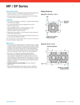
Step 5 — Make Piping Connections — See
Fig. 13 and 14 for typical piping applications.
30HK, HWC, HWS CONDENSER DESCRIPTION — All
30HWC and HWS units use a shell-and-tube condenser with
removable heads for easy tube servicing. Refrigerant is con-
tained within the shell, and water flows through the tubes.
The 30HK and HWC units use a steel shell condenser(s) with
steel tube sheets and copper tubes. The 30HWS units are
designed for sea coast applications and use a steel shell con-
denser with cupronickel tube sheets and tubes. In addition,
the 30HWS water heads utilize ‘‘sacrificial’’ zinc anodes for
condenser corrosion protection.
IMPORTANT: Inspect the zinc anodes every 3 months
for deterioration and replace as needed. Galvanic pro-
tection of the condenser is lost if the anodes are not
replaced prior to complete deterioration.
The number of tubes in the condenser(s) varies depending
on the unit size. The condensers have internal subcoolers which
provide approximately 8 F (4.4 C) for 30HK, HLunits or 13 F
(7.2 C) for 30HW units subcooling at ARI (Air Condition-
ing and Refrigeration Institute, U.S.A.) rating conditions.
30HL, HWA SYSTEM CONDENSER — For detailed con-
denser piping installation instructions for 30HL and HWA
systems, refer to separate instructions packaged with the re-
mote condenser unit(s).
Condenser refrigerant piping for 30HLand HWAunits should
be sized to minimize the amount of refrigerant required.
The 30HL and HWA units that use an air-cooled evapo-
rative condenser(s) must have adequate means for head pres-
sure control when operating below 60 F (15.6 C).
Carrier recommends that a field-supplied pressure relief
device be installed after the muffler in each discharge line.
Most local codes require the relief valve to be vented di-
rectly to the outdoors. The vent must not be smaller than the
relief valve outlet.
30HWB CONDENSER DESCRIPTION —All 30HWB units
use a brazed-plate heat-exchanger-type condenser. These heat
exchangers are made of embossed plates of acid-resistant stain-
less steel. Every other plate is reversed so that the ridges of
the herringbone pattern intersect one another on adjacent plates,
forming a lattice of contact points. These plates are vacuum-
brazed together to form a compact and pressure-resistant heat
exchanger.
After brazing, the impressions in the plates form 2 sepa-
rate systems of channels where the refrigerant and water flows
are counter-current. The number of plates varies depending
on unit tonnage. The condensers provide approximately 14°
to 18° F (8° to 10° C) liquid subcooling at the standard
Air Conditioning and Refrigeration Institute (ARI) rating
condition.
30HK, HWC, HWS CONDENSER(S) — When facing the
front of the unit, the condenser(s) is in the uninsulated shell(s)
located across the bottom of the unit. The water connections
are such that the water inlet is located on the left-hand side
(30HK) or right-hand side (30HW) of the unit. The water
inlet must ALWAYS be on the bottom of the condenser(s) to
provide the proper subcooling. The water outlet is located
on the right-hand side (30HK) or left-hand side (30HW) of
the unit. The water connections can be reversed by rotating
the heads and gaskets 180 degrees ON BOTH ENDS OF
THE CONDENSER(S).
IMPORTANT: THE WATER INLET MUST AL-
WAYS BE ON THE CONDENSER HEAD(S) THAT
HAS THE NOZZLE CONNECTION AT THE BOT-
TOM OF THE HEAD. Incorrect inlet connection will
result in poor system performance due to incorrect
subcooling.
The LIQUID-IN and LIQUID-OUT labels indicate water
connections AS SUPPLIED FROM THE FACTORY.
It is recommended that strainer with a minimum of 20 mesh
be installed ahead of the condenser water inlet(s) to prevent
debris from clogging or damaging the heat exchanger(s).
There is a pressure-relief device on the condenser(s) of all
30HK, HWC, and HWS units. Most local codes require that
this relief be vented directly to the outdoors.
NOTE: The relief line must not be smaller than the relief
valve outlet. Be sure to provide a way of draining and ser-
vicing the unit.
THUMB-SCREW
BRAKE
Fig. 11 — Factory-Installed Unit Wheels (4)
Fig. 12 — Compressor Mounting
13

Fig. 13 — Typical Piping with Fluid-Cooled 30HWB Unit Shown
NOTES:
1. Chiller must be installed
levelly
to maintain proper compressor oil return.
2. Wiringand piping shown are general points-of-connection guides only and are not intended for a specific installation. Wiring and piping
shown are for a quick overview of system and are not in accordance with recognized standards.
3. All wiring must comply with applicable local and national codes.
4. All piping must follow standard piping techniques. Refer to Carrier System Design Manual or appropriateASHRAE (American Society
of Heating, Refrigeration, and Air Conditioning Engineers) handbook for details.
5. See Table 3 on page 17 for minimum system fluid volume. This system may require the addition of a holding tank to ensure adequate
volume.
LEGEND
Airflow Through Condenser
Airflow Through Air
Handling Unit
Power Wiring
Control Wiring
Chilled Water Piping
ST — Field-Supplied Starter
FD — Field-Supplied Disconnect
FS — Field-Supplied Differential
Flow Switch
*Field Supplied.
14

Fig. 14 — Typical Piping with Air-Cooled 30HWA with Remote 09DK Unit Shown
NOTES:
1. Chiller must be installed
levelly
to maintain proper compres-
sor oil return.
2. Wiringandpipingshown aregeneralpoints-of-connectionguides
only and are not intended for a specific installation. Wiring
and piping shown are for a quick overview of system and are
not in accordance with recognized standards.
3. Allwiringmust complywithapplicable localand nationalcodes.
4. All piping must follow standard piping techniques. Refer to
Carrier System Design Manual part 3, Carrier E20-IIT soft-
ware Refrigerant Piping program, or appropriate ASHRAE
(American Society of Heating, Refrigeration, and Air Condi-
tioningEngineers)handbook for detailson proper pipingsizes
and design.
5. See Table 3 on page 17 for minimum system fluid volume.
This system may require the addition of a holding tank to en-
sure adequate volume.
6. Hotgas lines should rise above refrigerant levelincondenser
circuit. Doubleriser may be required;checkcompressor mini-
mum capacity.
7. Trap should be installed on hot gas lines to prevent con-
denser oil and refrigerant vapor migration from accumulating
on compressor heads during off cycle.
8. Pitch all horizontal lines downward in the direction of refrig-
erant flow.
9. Forpipinglengths greater than 50 ft, provide support to liquid
and gas lines near the connections to the condenser coil.
10. For pressure relief requirements, see latest revision of
ASHRAE Standard 15, Safety Code for Mechanical
Refrigeration.
15

30HWB CONDENSER — When facing the back of the unit,
the condenser is the uninsulated heat exchanger located on
the right-hand side. The water connections are on the right-
hand side of the heat exchanger with the LIQUID-IN con-
nection at the bottom, and the LIQUID-OUT connection at
the top.
A strainer with a minimum of 20 mesh must be installed
ahead of the condenser water inlet to prevent debris from
clogging or damaging the heat exchanger.
To install the grooved end coupling (see Fig. 15):
1. Lubricate the gasket lips and stretch the gasket over
the end of the pipe. Avoid twisting the gasket when
installing.
2. Bring the pipe and heat exchanger coupling ends to-
gether into alignment. Slide the gasket so that it is cen-
tered over the ends. Apply a light film of lubricant to the
gasket, or to the gasket recess of the coupling housing.
Avoid twisting the gasket during installation.
3. Seat the coupling halves over the gasket and install the
nuts and bolts. Tighten the nuts equally on both sides.
4. Alternately tighten the nuts with a wrench to draw
the coupling halves together uniformly. The joint is now
complete.
30HK, HWB, HWC, HWS UNITS — In order to minimize
the water pressure drop in the system, use as few bends as
possible in the field water piping, and run the lines as short
as possible. Size the water lines according to the available
pump pressure (not necessarily the connection size), espe-
cially on cooling tower applications. See Carrier System De-
sign Manual, Part 3, Piping Design. See Fig. 16 for condenser
pressure drops.
Set water regulating valve to maintain design head pres-
sure. Do not adjust to compensate for high head pressures
caused by fouled condenser tubes, excess refrigerant, or
the presence of noncondensables. Due to changes in water
temperature, it may be necessary to adjust the valve season-
ally.After adjusting for design head pressure, shut unit down.
The water regulating valve should shut off the flow of water
in a few minutes. If it does not, raise head pressure setting.
Make sure that the capillary tube from each water regulating
valve is connected to the proper condenser purge valve.
Provide a means for draining the system in the winter (if
not used) and for maintenance.
Accessory steel manifold packages for inlet and outlet con-
denser water are available for 30HK units. Each manifold is
furnished in 2 sections, to be field welded as shown in
Fig. 4. Manifolds should not be used where regulating valves
are required because separate valves must be used on each
condenser circuit.
Retighten all condenser head bolts before filling system
with water. Torque bolts to a maximum of 40 to
45 ft-lb.
Water leaving the condenser is under pressure and should
not be connected directly into sewer lines. Check local codes.
A 3/8-in. drain plug is located in the head at each condenser
end.
Refer to Pressure Relief Devices and Discharge Line Check
Valve sections on page 28, concerning piping connections
for these components.
COOLER DESCRIPTION
30HK, HL Units — The cooler is a direct-expansion type
with removable heads and is partitioned for multi-pass re-
frigerant flow. Fluid flow across the tube bundle is directed
by baffles designed for minimum fluid-pressure drop. The
tubes have integral internal fins for maximum heat transfer
efficiency.
Viewed from unit front, the return chilled fluid enters at
the left end of the cooler and leaves at the right end. The
sensing bulb for the factory-supplied fluid temperature con-
troller is in the leaving-fluid nozzle; the leaving-fluid tem-
perature being the control point.
The cooler is insulated with a flexible, closed-cell plastic
foam insulation of suitable thickness. Fluid vapor cannot pen-
etrate the cellular structure to condense either within cells or
on the cooler shell. Thus, the insulation itself is a vapor bar-
rier. Because of the toughness of insulation, a protective sheet
metal covering is not necessary.
Special modification may be necessary for brine chillers.
Contact your Carrier representative for details. For calcium
or sodium chloride brines, it is important that the proper in-
hibitors be carefully selected for protection of the copper tubes.
Refer to the publications of the Calcium Institute or the
Mutual Chemical Division of Allied Chemical Corporation
for information on corrosion control for calcium or sodium
chloride systems.
30HW Units — All 30HW units use a brazed-plate heat-
exchanger type cooler. The heat exchanger is constructed es-
sentially the same as the brazed-plate condenser used on
30HWB units. See 30HWB Condenser Description section
on page 13 for more details. Similar to the condenser, the
cooler can only be chemically cleaned.
COOLER PIPING — Plan cooler fluid piping for minimum
number of changes in elevation, and for the fewest number
of bends as possible. Install manual or automatic vent valve
at high points in the line. Maintain system pressure by using
a pressure tank or a combination or relief and reducing valves.
A strainer with a minimum of 20 mesh must be installed
ahead of the cooler fluid inlet to prevent debris from clog-
ging or damaging the heat exchanger.
See Carrier System Design Manual, Part 3, Piping
Design, for chilled fluid piping details.
Fig. 15 — Installed Coupling Fastening Grooved
Pipe Ends
16

The cooler fluid inlet and outlet connections are grooved-
end. On 30HW units, the fluid enters at the top connection
and leaves at the bottom connection. Procedures for making
the grooved-end connections are the same as for the 30HWB
condensers. See 30HWB Condenser section on page 16 for
more details.
Run the pump for 10 minutes, then clean the strainer be-
fore starting the unit.
A cooler flow switch must be field-installed on all units.
This should be a differential pressure switch that is installed
between the cooler fluid inlet and outlet. The switch should
be set to open when the cooler fluid flow drops below the
values shown in Table 3. Use the cooler water pressure drop
curves (Fig. 16) to determine correct setting for each unit
size. Use Carrier accessory flow switch, part number
30HW900003. See Table 3 for Minimum Flow rates and loop
volumes.
See Step 6 — Make Electrical Connections section on
page 19 for flow switch wiring details.
30HK, HL Units — The thermistor used for sensing fluid
temperature is factory-installed in the cooler leaving fluid
line.
30HW Units — The thermistor used for sensing the fluid
temperature is inside the cooler leaving-water cavity.
Table 3 — Minimum Cooler and Condenser Flow
Rates Minimum Loop Volume
UNIT SIZE
COOLER CONDENSER*
MINIMUM COOLER
LOOP VOLUME†
Gal./Min L/s Gal./Min L/s Gal. L
30HK040 56.0 3.5 67 4.23 120 454.2
30HK,HL050 68.0 4.3 76 4.79 148 560.2
30HK,HL060 68.0 4.3 83 5.24 174 658.6
30HW018 22.5 1.4 22.5 1.4 44 167
30HW025 30.0 1.9 30.0 1.9 59 223
30HW028 37.5 2.4 37.5 2.4 76 288
30HW035 45.0 2.8 45.0 2.8 85 322
30HW040 57.0 3.6 57.0 3.6 113 428
LEGEND
ARI — Air Conditioning and Refrigeration Institute
N—Liters per kW
V—Gallons per ton
*30HK, HWB, HWC and HWS only.
†Minimum system fluid volumes.
NOTES:
Gallons=VxARIcapacity in tons.
Liters=NxARIcapacity in kW.
APPLICATION V N
Normal Air Conditioning 3 3.25
Process Type Cooling 6 to 10 6.5 to 10.8
Low Ambient Operation 6 to 10 6.5 to 10.8
COOLER PRESSURE DROP — 30HW UNITS COOLER PRESSURE DROP — 30HK, HL UNITS
NOTE: Ft of water = 2.31 x change in psig.
Fig. 16 — Cooler and Condenser Water Pressure Drop
17

CONDENSER PRESSURE DROP —
30HK UNITS
CONDENSER PRESSURE DROP —
30HWB UNITS
NOTE:Ft ofwater = 2.31 xchange
in psig.
Fig. 16 — Cooler and Condenser Water Pressure Drop (cont)
CONDENSER PRESSURE DROP —
30HWC AND 30HWS UNITS
18

Step6 — Make Electrical Connections — All field
wiring must comply with local code requirements. Electrical
data for the complete unit and for the compressors is shown
in Tables 4A and 4B. See Fig. 17 and 18 for field wiring
connections.Afield-supplied branch circuit disconnect switch
that can be locked in either OPEN or OFF position must be
installed.
30HK, HL UNITS — On all 60 Hz units, a fused (15 amp
maximum), 115 v control circuit must be supplied by either
a separate power source or by using a minimum 300 va trans-
former. On 208/230 and 460 v units, control circuit power
can be supplied by accessory transformer part no. 07EA900051.
Check to be sure that installation of the 115 v control power
source meets all local codes.
On all 50 Hz units, a fused (15 amp maximum), 230 v
control circuit must be field supplied. On 200-3-50 units, power
for the control circuit can be supplied by connecting a field-
supplied fuse (15 amp maximum) between TB1 and TB2 for
L1 overcurrent protection. On 400-3-50 units, power for the
control circuit can be supplied by connecting a field-
supplied fuse (15 amp maximum) between TB1 and a neu-
tral leg from TB2 for L1 overcurrent protection. On all units,
check to be sure that installation of the 230 v control power
source meets all local codes.
30HW UNITS — Control circuit power is 24 v and 115 v
on all units, and is supplied by factory-installed control
transformers.
ALL UNITS — Inside the control box are terminals for field
power and ground (earth) wiring, as well as a terminal for a
neutral wire when needed (380-3-60 and 400-3-50 units only).
A ground wire must be installed with each field power sup-
ply. Compressor are wired standard from the factory for across-
the-line start. As a factory-installed option, all 025-060 sizes
are available wired for part-wind start (special order option
on 30HK, HL unit).
Refer to Tables 4A and 4B for electrical data.
Flow Switch —Acooler flow switch is required for all units,
and must be field-installed. The Carrier flow switch acces-
sory (part number 30HW900003), is available for this pur-
pose. Flow switch wiring terminals are located in the field
wiring compartment of the control box. The flow switch should
be wired between terminals TB3-1 and TB3-7 for 30HK, HL
units or between terminals TB2-7 and TB2-13 for 30HW units.
The factory jumper wire between these 2 terminals must be
removed for proper operation of the flow switch.
Control Box, Power Section — The electrical power supply
is brought in through the top left-hand side (30HK, HL) or
right-hand side (30HW) of the control box (see Fig. 19 and
20). The knockout accepts up to a 3-in. (76 mm) conduit for
30HK, HL units, and a 1
3
⁄
4
-to2
1
⁄
2
-in. (44 to 64 mm) conduit
for 30HW units. Pressure-lug connections on the terminal
blocks are suitable for copper, copper-clad aluminum, or alu-
minum conductors.
The control box power section contains the following
components:
• power terminal block
• compressor circuit breaker(s)
• compressor contactor(s)
• high-voltage transformer (30HW units only)
• control-circuit circuit breaker for 24-v circuit
• unit ON-OFF switch
• unit service light
• ground lug
• neutral terminal (380-3-60 and 400-3-50 units)
• terminal block for ground current sensing accessory
Control Box, Controls Section — The control box controls
section contains the following components:
• temperature controller
• control relay(s)
• control module(s)
• low-voltage control transformer(s)
• terminal block for ground current sensing accessory
Control Box, Field Control Wiring Section — Inside this
section is a 10-terminal (30HK, HL) or 14-terminal (30HW),
low-voltage, field-wiring terminal strip.All low-voltage field-
wiring connections are made to this terminal block. Seven
3
⁄
4
-in. (19 mm) knockouts are provided for field wiring in
this section. Connections for chilled fluid flow switch, chilled
fluid pump interlock, condenser pump interlock, remote alarm
output, and ground current sensor accessory are made at this
location. The remote condenser relay connections are made
to a separate 4-terminal (30HK, HL) or 3-terminal (30HW)
field wiring strip. See Fig. 17-20 for specific location of
connections.
Unbalanced 3-Phase Supply Voltage — Never operate acom-
pressor where a phase imbalance in the supply voltage is
greater than 2%. Use the following formula to determine
the percent voltage imbalance:
% Voltage Imbalance =
max voltage deviation from average voltage
100 x
average voltage
Example: Supply voltage is 240-3-60
AB = 243 v
BC = 236 v
AC = 238 v
243 + 236 + 238
Average Voltage =
3
= 239 v
Determine maximum deviation from average voltage:
(AB) 243 - 239=4v
(BC) 239 - 236=3v
(AC) 239 - 238=1v
Maximum deviation is 4 v.
Determine percent voltage imbalance:
4
% Voltage Imbalance = 100 x
239
= 1.7%
This amount of phase imbalance is satisfactory as it is below
the maximum allowable 2%.
IMPORTANT: If the supply voltage phase imbalance
is more than 2%, contact your local utility company
immediately.
19

Table 4A — Electrical Data — 30HK, HWB, HWC, HWS Fluid-Cooled Units
UNIT SIZE
30-
UNIT COMPRESSOR (ea)
Volts Voltage*
MCA
ICF
MFA
Rec
Fuse
RLA
LRA MTA
Nameplate (3 ph) Hz Min Max PW XL PW XL PW XL
HK040
208/230 60 187 253 129 † 340 175 150 57 † 283 † 89
460 60 414 518 59 † 168 80 70 26 † 142 † 40
575 60 518 632 54 † 122 70 60 24 † 98 † 42
220 50 198 253 142 † 390 200 175 75/48** † 342/201** † 116/74**
400 50 342 440 71 † 249 100 90 36/26** † 223/142** † 56/40**
HK050
208/230 60 187 253 161 † 503 225 200 83/57** † 446/283** † 89/64**
460 60 414 518 75 † 249 110 90 39/26** † 223/142** † 56/40**
575 60 518 632 73 † 188 110 90 39/24** † 164/ 88** † 54/37**
220 50 198 253 169 † 417 225 200 75 † 342 † 116
400 50 342 440 81 † 259 110 100 36 † 223 † 56
HK060
208/230 60 187 253 187 † 529 250 225 83 † 446 † 64
460 60 414 518 88 † 262 125 100 39 † 223 † 56
575 60 518 632 88 † 203 125 100 39 † 164 † 54
220 50 198 253 225 † 600 300 250 100 † 545 † 156
400 50 342 440 131 † 403 175 150 58 † 345 † 90
HWB,C,S018
208/230 60 187 253 62 — 266 110 80 49 — 266 — 89
380 60 342 418 35 — 145 60 45 28 — 145 — 40
460 60 414 508 28 — 120 50 35 23 — 120 — 33
575 60 518 632 24 — 96 40 30 19 — 96 — 25
230 50 198 253 58 — 200 100 70 46 — 200 — 63
380/415 50 342 440 34 — 115 60 45 27 — 115 — 41
HWB,C,S025
208/230 60 187 253 72 170 283 125 90 57 170 283 88 88
380 60 342 418 43 85 142 70 60 34 85 142 52 52
460 60 414 508 34 85 142 60 45 27 85 142 40 42
575 60 518 632 28 59 98 45 35 22 59 98 33 33
230 50 198 253 67 150 250 110 80 53 150 250 80 80
380/415 50 342 440 38 104 173 60 45 30 104 173 44 44
HWB,C,S028
208/230 60 187 253 89 268 446 150 110 71 268 446 104 104
380 60 342 418 54 134 223 90 70 43 134 223 66 66
460 60 414 508 44 134 223 70 60 35 134 223 50 52
575 60 518 632 35 98 164 60 45 28 98 164 41 42
230 50 198 253 85 205 342 150 110 68 205 342 98 98
380/415 50 342 440 54 134 223 90 70 43 134 223 60 60
HWB,C,S035
208/230 60 187 253 102 268 446 175 125 81 268 446 120 120
380 60 342 418 59 134 223 100 80 47 134 223 70 70
460 60 414 508 48 134 223 80 60 38 134 223 52 57
575 60 518 632 39 98 164 60 50 31 98 164 42 42
230 50 198 253 94 220 366 150 125 75 220 366 112 112
380/415 50 342 440 54 152 253 90 70 43 152 253 66 66
HWB,C,S040
208/230 60 187 253 145 414 690 250 175 116 414 690 180 180
380 60 342 418 84 207 345 150 110 67 207 345 98 98
460 60 414 508 69 207 345 110 90 55 207 345 78 84
575 60 518 632 55 165 276 90 70 44 165 276 63 66
230 50 198 253 135 327 545 225 175 108 327 545 166 166
380/415 50 342 440 78 207 345 125 100 62 207 345 98 98
20
/