Page is loading ...

INSTRUCTION MANUAL
DC-380 15" Planer
(Model 22-680, Single Phase)
(Model 22-681, Three Phase)
PART NO. 1346996 - 07-30-04
Copyright © 2004 Delta Machinery
To learn more about DELTA MACHINERY
visit our website at: www.deltamachinery.com.
For Parts, Service, Warranty or other Assistance,
please call
1-800-223-7278 (In Canada call 1-800-463-3582).
Shown with Delta
Model 50-654 Accessory
Planer Stand and
Roller Extension Tables

2
TABLE OF CONTENTS
Read and understand all warnings and operating instructions before using any tool or equipment. When
using tools or equipment, basic safety precautions should always be followed to reduce the risk of personal injury.
Improper operation, maintenance or modification of tools or equipment could result in serious injury and property
damage. There are certain applications for which tools and equipment are designed. Delta Machinery strongly
recommends that this product NOT be modified and/or used for any application other than for which it was designed.
If you have any questions relative to its application DO NOT use the product until you have written Delta Machinery
and we have advised you.
Online contact form at www.deltamachinery.com
Postal Mail: Technical Service Manager
Delta Machinery
4825 Highway 45 North
Jackson, TN 38305
Information regarding the safe and proper operation of this tool is available from the following sources:
Power Tool Institute
1300 Sumner Avenue, Cleveland, OH 44115-2851
www
.powertoolinstitute.org
National Safety Council
1121 Spring Lake Drive, Itasca, IL 60143-3201
American National Standards Institute, 25 West 43rd Street, 4 floor, New York, NY 10036 www.ansi.org
ANSI 01.1Safety Requirements for Woodworking Machines, and
the U.S. Department of Labor regulations www
.osha.gov
IMPORTANT SAFETY INSTRUCTIONS
SAVE THESE INSTRUCTIONS!
IMPORTANT SAFETY INSTRUCTIONS . . . . . . . . . . . . . . . . . . . . . . . . . . . . . . . . . . . . . . . . . . . . . . . . . . . . . . . . . . .2
SAFETY GUIDELINES . . . . . . . . . . . . . . . . . . . . . . . . . . . . . . . . . . . . . . . . . . . . . . . . . . . . . . . . . . . . . . . . . . . . . . . .3
GENERAL SAFETY RULES . . . . . . . . . . . . . . . . . . . . . . . . . . . . . . . . . . . . . . . . . . . . . . . . . . . . . . . . . . . . . . . . . . . .4
ADDITIONAL SPECIFIC SAFETY RULES . . . . . . . . . . . . . . . . . . . . . . . . . . . . . . . . . . . . . . . . . . . . . . . . . . . . . . . . .5
FUNCTIONAL DESCRIPTION . . . . . . . . . . . . . . . . . . . . . . . . . . . . . . . . . . . . . . . . . . . . . . . . . . . . . . . . . . . . . . . . . .7
CARTON CONTENTS . . . . . . . . . . . . . . . . . . . . . . . . . . . . . . . . . . . . . . . . . . . . . . . . . . . . . . . . . . . . . . . . . . . . . . . . .8
ASSEMBLY . . . . . . . . . . . . . . . . . . . . . . . . . . . . . . . . . . . . . . . . . . . . . . . . . . . . . . . . . . . . . . . . . . . . . . . . . . . . . . . . .9
OPERATION . . . . . . . . . . . . . . . . . . . . . . . . . . . . . . . . . . . . . . . . . . . . . . . . . . . . . . . . . . . . . . . . . . . . . . . . . . . . . . .12
TROUBLESHOOTING . . . . . . . . . . . . . . . . . . . . . . . . . . . . . . . . . . . . . . . . . . . . . . . . . . . . . . . . . . . . . . . . . . . . . . .21
MAINTENANCE . . . . . . . . . . . . . . . . . . . . . . . . . . . . . . . . . . . . . . . . . . . . . . . . . . . . . . . . . . . . . . . . . . . . . . . . . . . . .22
SERVICE . . . . . . . . . . . . . . . . . . . . . . . . . . . . . . . . . . . . . . . . . . . . . . . . . . . . . . . . . . . . . . . . . . . . . . . . . . . . . . . . . .23
ACCESSORIES . . . . . . . . . . . . . . . . . . . . . . . . . . . . . . . . . . . . . . . . . . . . . . . . . . . . . . . . . . . . . . . . . . . . . . . . . . . .23
WARRANTY . . . . . . . . . . . . . . . . . . . . . . . . . . . . . . . . . . . . . . . . . . . . . . . . . . . . . . . . . . . . . . . . . . . . . . . . . . . . . . . .23
SERVICE CENTER LOCATIONS . . . . . . . . . . . . . . . . . . . . . . . . . . . . . . . . . . . . . . . . . . . . . . . . . . . . . . . .back cover

3
Indicates an imminently hazardous situation which, if not avoided, will result in death or serious injury.
Indicates a potentially hazardous situation which, if not avoided, could result in death or serious injury.
Indicates a potentially hazardous situation which, if not avoided, may result in minor or moderate injury.
Used without the safety alert symbol indicates potentially hazardous situation which, if not avoided, may
result in property damage.
It is important for you to read and understand this manual. The information it contains relates to protecting YOUR
SAFETY and PREVENTING PROBLEMS. The symbols below are used to help you recognize this information.
SAFETY GUIDELINES - DEFINITIONS
SOME DUST CREATED BY POWER SANDING, SAWING, GRINDING, DRILLING, AND OTHER
CONSTRUCTION ACTIVITIES contains chemicals known to cause cancer, birth defects or other reproductive harm.
Some examples of these chemicals are:
· lead from lead-based paints,
· crystalline silica from bricks and cement and other masonry products, and
· arsenic and chromium from chemically-treated lumber.
Your risk from these exposures varies, depending on how often you do this type of work. To reduce your exposure to
these chemicals: work in a well ventilated area, and work with approved safety equipment, always wear MSHA/NIOSH
approved, properly fitting face mask or respirator when using such tools.
CALIFORNIA PROPOSITION 65

4
GENERAL SAFETY RULES
READ AND UNDERSTAND ALL WARNINGS AND OPERATING INSTRUCTIONS BEFORE
USING THIS EQUIPMENT. Failure to follow all instructions listed below, may result in electric shock,
fire, and/or serious personal injury or property damage.
IMPORTANT SAFETY INSTRUCTIONS
1. FOR YOUR OWN SAFETY, READ THE INSTRUCTION
MANUAL BEFORE OPERATING THE MACHINE.
Learning the machine’s application, limitations, and
specific hazards will greatly minimize the possibility of
accidents and injury.
2. WEAR EYE PROTECTION. ALWAYS USE SAFETY
GLASSES. Also use face or dust mask if cutting
operation is dusty. Everyday eyeglasses are NOT safety
glasses. USE CERTIFIED SAFETY EQUIPMENT. Eye
protection equipment should comply with ANSI Z87.1
standards, hearing equipment should comply with
ANSI S3.19 standards, and dust mask protection
should comply with MSHA/NIOSH certified respirator
standards. Splinters, air-borne debris, and dust can
cause irritation, injury, and/or illness.
3. WEAR PROPER APPAREL. Do not wear loose
clothing, gloves, neckties, rings, bracelets, or other
jewelry which may get caught in moving parts. Nonslip
footwear is recommended. Wear protective hair
covering to contain long hair.
4. DO NOT USE THE MACHINE IN A DANGEROUS
ENVIRONMENT. The use of power tools in damp or
wet locations or in rain can cause shock or
electrocution. Keep your work area well-lit to prevent
tripping or placing arms, hands, and fingers in danger.
5. MAINTAIN ALL TOOLS AND MACHINES IN PEAK
CONDITION. Keep tools sharp and clean for best and
safest performance. Follow instructions for lubricating
and changing accessories. Poorly maintained tools and
machines can further damage the tool or machine
and/or cause injury.
6. CHECK FOR DAMAGED PARTS. Before using the
machine, check for any damaged parts. Check for
alignment of moving parts, binding of moving parts,
breakage of parts, and any other conditions that may
affect its operation. A guard or any other part that is
damaged should be properly repaired or replaced.
Damaged parts can cause further damage to the
machine and/or injury.
7. KEEP THE WORK AREA CLEAN. Cluttered areas and
benches invite accidents.
8. KEEP CHILDREN AND VISITORS AWAY. Your shop is a
potentially dangerous environment. Children and visitors can
be injured.
9. REDUCE THE RISK OF UNINTENTIONAL STARTING.
Make sure that the switch is in the “OFF” position
before plugging in the power cord. In the event of a
power failure, move the switch to the “OFF” position.
An accidental start-up can cause injury.
10. USE THE GUARDS. Check to see that all guards are in
place, secured, and working correctly to prevent injury.
11. REMOVE ADJUSTING KEYS AND WRENCHES
BEFORE STARTING THE MACHINE. Tools, scrap
pieces, and other debris can be thrown at high speed,
causing injury.
12. USE THE RIGHT MACHINE. Don’t force a machine or
an attachment to do a job for which it was not
designed. Damage to the machine and/or injury may
result.
13. USE RECOMMENDED ACCESSORIES. The use of
accessories and attachments not recommended by
Delta may cause damage to the machine or injury to the
user.
14. USE THE PROPER EXTENSION CORD. Make sure
your extension cord is in good condition. When using
an extension cord, be sure to use one heavy enough to
carry the current your product will draw. An undersized
cord will cause a drop in line voltage, resulting in loss of
power and overheating. See the Extension Cord Chart
for the correct size depending on the cord length and
nameplate ampere rating. If in doubt, use the next
heavier gauge. The smaller the gauge number, the
heavier the cord.
15. SECURE THE WORKPIECE. Use clamps or a vise to hold
the workpiece when practical. Loss of control of a
workpiece can cause injury.
16. FEED THE WORKPIECE AGAINST THE DIRECTION OF
THE ROTATION OF THE BLADE, CUTTER, OR ABRASIVE
SURFACE. Feeding it from the other direction will cause
the workpiece to be thrown out at high speed.
17. DON’T FORCE THE WORKPIECE ON THE MACHINE.
Damage to the machine and/or injury may result.
18. DON’T OVERREACH. Loss of balance can make you
fall into a working machine, causing injury.
19. NEVER STAND ON THE MACHINE. Injury could occur if the
tool tips, or if you accidentally contact the cutting tool.
20. NEVER LEAVE THE MACHINE RUNNING UNATTENDED.
TURN THE POWER OFF. Don’t leave the machine until it
comes to a complete stop. A child or visitor could be injured.
21. TURN THE MACHINE “OFF”, AND DISCONNECT THE
MACHINE FROM THE POWER SOURCE before installing
or removing accessories, before adjusting or changing
set-ups, or when making repairs. An accidental start-up
can cause injury.
22. MAKE YOUR WORKSHOP CHILDPROOF WITH
PADLOCKS, MASTER SWITCHES, OR BY
REMOVING STARTER KEYS. The accidental start-up
of a machine by a child or visitor could cause injury.
23. STAY ALERT, WATCH WHAT YOU ARE DOING, AND
USE COMMON SENSE. DO NOT USE THE
MACHINE WHEN YOU ARE TIRED OR UNDER THE
INFLUENCE OF DRUGS, ALCOHOL, OR
MEDICATION. A moment of inattention while operating
power tools may result in injury.
24. TAKE PRECAUTIONS AGAINST DUST INHALATION.
The dust generated by certain woods and wood
products can be injurious to your health. Always
operate machinery in well-ventilated areas, and provide
for proper dust removal. Use wood dust collection
systems whenever possible.

5
ADDITIONAL SAFETY RULES FOR PLANERS
FAILURE TO FOLLOW THESE RULES MAY RESULT IN SERIOUS PERSONAL INJURY
SAVE THESE INSTRUCTIONS.
Refer to them often
and use them to instruct others.
1. DO NOT OPERATE THIS MACHINE until it is
completely assembled and installed according to
the instructions. A machine incorrectly assembled
can cause serious injury.
2. OBTAIN ADVICE from your supervisor, instructor,
or another qualified person if you are not
thoroughly familiar with the operation of this
machine. Knowledge is safety.
3. FOLLOW ALL WIRING CODES and recommend-
ed electrical connections to prevent shock or
electrocution.
4. KEEP KNIVES SHARP and free from rust and
pitch. Dull or rusted knives work harder and can
cause kickback.
5. NEVER TURN THE MACHINE “ON” before clearing
the table of all objects (tools, scraps of wood, etc.).
Flying debris can cause serious injury.
6. NEVER TURN THE MACHINE “ON” with the work-
piece contacting the cutterhead. Kickback can
occur.
7. SECURE THE MACHINE TO A SUPPORTING SUR-
FACE to prevent the machine from sliding, walking
or tipping over.
8. PROPERLY SECURE THE KNIVES IN THE CUTTER-
HEAD before turning the power “ON”. Loose
blades may be thrown out at high speeds causing
serious injury.
9. LOCK THE SPEED SETTING SECURELY before
feeding the workpiece through the machine.
Changing speeds while planing can cause kick-
back.
10. AVOID AWKWARD OPERATIONS AND HAND POSIT-
IONS. A sudden slip could cause a hand to move
into the knives.
11. KEEP ARMS, HANDS, AND FINGERS away from
the cutterhead, the chip exhaust opening, and the
feed rollers to prevent severe cuts.
12. NEVER REACH INTO THE CUTTERHEAD AREA
while the machine is running. Your hands can be
drawn into the knives.
13. DO NOT STAND IN LINE OF THE WORKPIECE.
Kickback can cause injury.
14. ALLOW THE CUTTERHEAD TO REACH FULL SPEED
before feeding a workpiece. Changing speeds
while planing can cause kickback.
15. WHEN PLANING BOWED STOCK, place the concave
(cup down) side of the stock on the table and cut
with the grain to prevent kickback.
16. DO NOT FEED A WORKPIECE that is warped,
contains knots, or is embedded with foreign
objects (nails, staples, etc.). Kickback can occur.
17. DO NOT FEED A SHORT, THIN, OR NARROW
WORKPIECE INTO THE MACHINE. Your hands can
be drawn into the knives and/or the workpiece can
be thrown at high speeds. See the “OPERATION”
section of this instruction manual for details.
18. DO NOT FEED A WORKPIECE into the outfeed end of
the machine. The workpiece will be thrown out of
the opposite side at high speeds.
19. REMOVE SHAVINGS ONLY with the power “OFF” to
prevent serious injury.
20. PROPERLY SUPPORT LONG OR WIDE WORK-
PIECES. Loss of control of the workpiece can cause
serious injury.
21. NEVER PERFORM LAYOUT, ASSEMBLY or set-up
work on the table/work area when the machine is
running. Serious injury will result.
22. TURN THE MACHINE “OFF”, DISCONNECT IT FROM
THE POWER SOURCE, and clean the table/work
area before leaving the machine. LOCK THE
SWITCH IN THE “OFF” POSITION to prevent un-
authorized use. Someone else might accidentally
start the machine and cause injury to themselves
or others.
23. ADDITIONAL INFORMATION regarding the safe
and proper operation of power tools (i.e. a safety
video) is available from the Power Tool Institute,
1300 Sumner Avenue, Cleveland, OH 44115-2851
(www.powertoolinstitute.com). Information is also
available from the National Safety Council, 1121
Spring Lake Drive, Itasca, IL 60143-3201. Please
refer to the American National Standards Institute
ANSI 01.1 Safety Requirements for Woodworking
Machines and the U.S. Department of Labor
Regulations.

6
A separate electrical circuit should be used for your machines. This circuit should not be less than #12 wire and should
be protected with a 20 Amp time lag fuse. If an extension cord is used, use only 3-wire extension cords which have 3-
prong grounding type plugs and matching receptacle which will accept the machine’s plug. Before connecting the
machine to the power line, make sure the switch (s) is in the “OFF” position and be sure that the electric current is of
the same characteristics as indicated on the machine. All line connections should make good contact. Running on low
voltage will damage the machine.
DO NOT EXPOSE THE MACHINE TO RAIN OR OPERATE THE MACHINE IN DAMP LOCATIONS.
3. Grounded, cord-connected machines intended for
use on a supply circuit having a nominal rating
between 150 - 250 volts, inclusive:
If the machine is intended for use on a circuit that has an
outlet that looks like the one illustrated in Fig. A, the
machine will have a grounding plug that looks like the
plug illustrated in Fig. A. Make sure the machine is
connected to an outlet having the same configuration as
the plug. No adapter is available or should be used with
this machine. If the machine must be re-connected for
use on a different type of electric circuit, the re-
connection should be made by qualified service
personnel; and after re-connection, the machine should
comply with all local codes and ordinances.
IN ALL CASES, MAKE CERTAIN THE
RECEPTACLE IN QUESTION IS PROPERLY
GROUNDED. IF YOU ARE NOT SURE HAVE A
QUALIFIED ELECTRICIAN CHECK THE RECEPTACLE.
POWER CONNECTIONS
MOTOR SPECIFICATIONS
The motor supplied with your 15” Planer is either a three horsepower, single phase motor, or a three horsepower, three
phase motor. The three horsepower, single phase motor is wired for 230 Volt operation and the three horsepower, three
phase motor is wired for 200-220 Volt operation. Before connecting the machine to the power source, make sure the
switch is in the “OFF” position.
GROUNDING INSTRUCTIONS
THIS MACHINE MUST BE GROUNDED WHILE IN USE TO PROTECT THE OPERATOR FROM
ELECTRIC SHOCK.
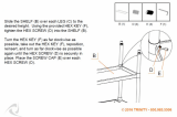
Fig. A
GROUNDED OUTLET BOX
CURRENT
CARRYING
PRONGS
GROUNDING BLADE
IS LONGEST OF THE 3 BLADES
230 VOLT, SINGLE PHASE OPERATION
If the motor on your machine is wired for 230 Volt, Single
Phase operation, the power cord from the motor is
equipped with a plug that has two flat, current-carrying
prongs in tandem, and one round or “U”-shaped longer
ground prong, as shown in Fig. A. This plug is used only
with the proper mating 3-conductor grounding type
receptacle as shown.
When the three prong plug on your machine is plugged
into a grounded 3-conductor receptacle, as shown in
Fig. A, the long ground prong on the plug contacts first
so that the machine is properly grounded before
electricity reaches it.
IN ALL CASES, MAKE CERTAIN THE
RECEPTACLE IN QUESTION IS PROPERLY
GROUNDED. IF YOU ARE NOT SURE HAVE A
QUALIFIED ELECTRICIAN CHECK THE RECEPTACLE.
4. Permanently connected machines:
If the machine is intended to be permanently connected,
the machine should be connected to a grounded metal
permanent wiring system, or to a system having an
equipment-grounding conductor.

7
EXTENSION CORDS
Use proper extension cords. Make sure
your extension cord is in good condition and is a 3-wire
extension cord which has a 3-prong grounding type
plug and matching receptacle which will accept the
machine’s plug. When using an extension cord, be sure
to use one heavy enough to carry the current of the
machine. An undersized cord will cause a drop in line
voltage, resulting in loss of power and overheating. Fig.
D shows the correct gauge to use depending on the
cord length. If in doubt, use the next heavier gauge. The
smaller the gauge number, the heavier the cord.
Fig. D
MINIMUM GAUGE EXTENSION CORD
RECOMMENDED SIZES FOR USE WITH STATIONARY ELECTRIC MACHINES
Ampere Total Length Gauge of
Rating Volts of Cord in Feet Extension Cord
0-6 240
up to
50 18 AWG
0-6 240 50-100 16 AWG
0-6 240 100-200 16 AWG
0-6 240 200-300 14 AWG
6-10 240
up to
50 18 AWG
6-10 240 50-100 16 AWG
6-10 240 100-200 14 AWG
6-10 240 200-300 12 AWG
10-12 240
up to
50 16 AWG
10-12 240 50-100 16 AWG
10-12 240 100-200 14 AWG
10-12 240 200-300 12 AWG
12-16 240
up to
50 14 AWG
12-16 240 50-100 12 AWG
12-16 240
GREATER THAN 100 FEET NOT RECOMMENDED
FOREWORD
FUNCTIONAL DESCRIPTION
Delta Model 22-680 is a 15" (381mm) Planer with adjustable feed rate for optimum planing under load. It has the
following cutting capacities; 15" (381mm) width, 6½" (165mm) thickness and 1/8" (5mm) depth of cut.
NOTICE: THE PHOTO ON THE MANUAL COVER ILLUSTRATES THE
CURRENT PRODUCTION MODEL. ALL OTHER ILLUSTRATIONS CONTAINED
IN THE MANUAL ARE REPRESENTATIVE ONLY AND MAY NOT DEPICT THE
ACTUAL COLOR, LABELING OR ACCESSORIES AND ARE INTENDED TO
ILLUSTRATE TECHNIQUE ONLY.
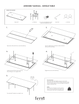
Fig. B
200-220 VOLT, THREE PHASE
OPERATION
If the motor on your machine is wired for 200-220 Volt,
Three Phase operation, proceed as follows when con-
necting your planer to an electrical power system:
1. Remove the two screws that attach the switch
cover (A) Fig. B, to the switch box and remove the
switch cover (A).
2. Remove lower right knockout from bottom of
switch box (B) Fig. C, and assemble a strain relief
(not supplied) in its place.
3. Bring the three phase power line up through the
strain relief, and connect the three power lines to
terminals L1, L2 and L3, shown at (C) Fig. C, and
connect the green ground wire to ground screw (D).
4. IMPORTANT: IF AFTER THE MACHINE IS IN
OPERATION THE CUTTERHEAD REVOLVES IN
THE WRONG ROTATION, INTERCHANGE ANY
TWO OF THE THREE POWER LINES THAT ARE
CONNECTED TO TERMINALS (C) FIG. C.
5. Replace switch cover that was removed in STEP 1.
THREE PHASE OPERATION
Three phase MACHINES are not supplied with a power
cord. They must be permanently connected to the
building electrical system and grounded according to
the National Electrical Code. Since they must be
permanently connected to the building electrical
system, extension cords cannot be used with three
phase MACHINES.
A
B
D
C
Fig. C

8
UNPACKING AND CLEANING
Carefully unpack the machine and all loose items from
the shipping container(s). Remove the protective coating
from all unpainted surfaces. This coating may be removed
with a soft cloth moistened with kerosene (do not use
acetone, gasoline or lacquer thinner for this purpose). After
cleaning, cover the unpainted surfaces with a good quality
household floor paste wax.
CARTON CONTENTS
Your new 15" Planer is shipped complete in one box
(Fig. 2). IMPORTANT: Care must be taken when
removing the machine from the container. The machine
is very heavy and a minimum of four people will be
required to lift the machine (see the section “LIFTING
THE MACHINE”). Figure 3 Illustrates the loose items
supplied with your machine.
Fig. 2
Fig. 3
1
2
4
12
11
13
14
15
16
18
17
10
9
8
7
6
5
3
1 - Top cover
2 - M6 x 16mm hex flange screw (4) - for fastening
top cover to machine
3 - Cord clamp
4 - Knife setting gage
5 - Raising and lowering handwheel
6 - Key for raising and lowering handwheel
7 - Decal for raising and lowering handwheel
8 - M10 flat washer for raising and lowering
handwheel
9 - M10 hex nut for raising and lowering handwheel
10 - Handle for raising and lowering handwheel
11 - Open end wrench (10 and 12mm)
12 - Open end wrench (14 and 17mm)
13 - Hex wrench (6mm)
14 - Hex wrench (5mm)
15 - Hex wrench (3mm)
16 - Hex wrench (2.5mm)
*17 - M6 x 16mm Screw (2) - for fastening switch
bracket to machine
*18 - M6 flat washer (2) - for fastening switch bracket
to machine
*Supplied with three phase machines only

9
ASSEMBLY
CUTTINGHEAD RAISING AND
LOWERING HANDWHEEL
1. Insert key (A) Fig. 7, into keyway (B) of raising and
lowering shaft.
Fig. 7
Fig. 8
2. Assemble handwheel (C) Fig. 8, to raising and lower-
ing shaft as shown. Make sure key, which was
assembled to shaft in STEP 1, is engaged with
keyway in hub of handwheel (C).
3. Assemble decal (D) Fig. 8, to raising and lowering
shaft as shown.
4. Fasten handwheel (C) Fig. 8, to raising and lowering
shaft using an M10 flat washer (E) and an M10 hex
nut (F) supplied.
5. Assemble handle (G) Fig. 8, to handwheel (C) as
shown.
B
A
G
C
D
F
E
LIFTING THE MACHINE
1. IMPORTANT: CARE MUST BE TAKEN WHEN
LIFTING THE MACHINE ONTO A STAND OR
WORKBENCH. THE PLANER IS VERY HEAVY
AND A MINIMUM OF FOUR PEOPLE WILL BE
REQUIRED TO LIFT THE MACHINE AS
FOLLOWS:
2. Raise the cuttinghead (A) Fig. 10, by turning the
raising and lowering handwheel (B) clockwise, and
insert two 6 or 8 foot long 2 x 4’s (C) between the
cuttinghead and table as shown. Lower the
cuttinghead just until it touches the 2 x 4 ‘s (C) Fig.
10, so that they are positioned solidly between the
table and cuttinghead. Then with two people on
each end of the 2 x 4’s, move the machine to its
desired location.
Fig. 10
C
A
B
6. Loosen two head locking knobs, one of which is
shown at (G) Fig. 9, and turn handwheel assembly
(H) clockwise to raise head assembly. Remove the
protective shipping block (J).
Fig. 9
J
H
G
FOR YOUR OWN SAFETY, DO NOT CONNECT THE MACHINE TO THE POWER SOURCE UNTIL THE
MACHINE IS COMPLETELY ASSEMBLED AND YOU READ AND UNDERSTAND THE ENTIRE INSTRUCTION
MANUAL.
ASSEMBLY TOOLS REQUIRED
ASSEMBLY TIME ESTIMATE - 2~3 hrs.
1) - Open end wrench (10 and 12mm) - provided 5) - Hex wrench (3mm) - provided
2) - Open end wrench (14 and 17mm) - provided 6) - Hex wrench (2.5mm) - provided
3) - Hex wrench (6mm) - provided 7) - 10, 12, 14, 17mm Sockets - not provided
4) - Hex wrench (5mm)
- provided 8) - 2 - 2 x 4’s
- not provided

10
ASSEMBLING SWITCH TO PLANER (THREE PHASE MACHINE ONLY)
The switch for the three phase 15² Planer is supplied wired to the motor and is to be fastened to the planer as
follows:
Fig. 10A
1. Line up the two holes (A) Fig. 10A, in the switch bracket (C) with the two threaded holes (B) in the left front of the
machine.
Fig. 10B
2. Fasten the switch bracket (C) Fig. 10B, to the planer using the two screws and flat washers (D) as shown.
B
B
C
C
D
A
A

11
ASSEMBLING TOP COVER AND
DUST CHUTE
1. Fasten the top cover and dust chute (A) Fig. 16, to
the top of the planer, as shown, using the three
M6x16mm screws (B) supplied. IMPORTANT: The
dust chute opening (C) must point to the rear as
shown.
Fig. 16
Fig. 17
2. Fasten the left corner of the cover to the top of the
planer using the remaining M6x16mm screw (D) Fig.
17, and cord clamp (E). NOTE: The motor cord (F)
must be inserted and positioned into the cord clamp
as shown.
D
E
F
B
B
C
A
Fig. 11
FRONT OF STAND
D
F
C
G
E
A
B
ASSEMBLING ACCESSORY 50-314
STAND
If you purchased the accessory 50-314 Stand for use
with your planer, assemble the stand as follows:
1. Assemble the stand, as shown in Fig. 11, using the
24 carriage bolts, 8 flat washers, 8 lockwashers
and 24 nuts supplied. NOTE: Eight carriage bolts
(A), flat washers, lockwashers and nuts are used to
mount the legs to the top shelf of the stand and
sixteen carriage bolts (B) and nuts are used to
mount the front, rear and side tie bars to the legs.
The two side tie bars (F), are 20-15/16" long and
the front and rear tie bars (D) are 23-7/16" long.
2. IMPORTANT: When lifting the planer to position it
on a stand or bench, refer to the following section:
“LIFTING THE MACHINE.”
3. The front end of the top shelf is indicated in Fig. 11.
Two slots (G), which are supplied on later models of
the 50-314 stand, indicate the rear end of the top
shelf. Place the machine on the top shelf with the
front (infeed) end of the machine toward the side of
the top shelf indicated as FRONT in Fig. 11. The
four holes in the base of the machine are to be
aligned with the four holes indicated on the top
shelf as (C) and (E) making sure that the left hand
side of the base will be over holes (E) and the right
hand side of the base will be over holes (C). The
offset between the top shelf of the stand and the
base of the planer will be on the left side. Mount
the machine to the top shelf using the four 1" long
hex head screws, flat washers, lock washers and
hex nuts supplied.

12
OPERATIONAL CONTROLS AND ADJUSTMENTS
Fig. 18
A
B
LOCKING SWITCH IN THE “OFF”
POSITION
IMPORTANT: When the machine is not in use, the switch
should be locked in the "OFF" position using a padlock
(C) Fig. 19, with a 3/16" diameter shackle to prevent
unauthorized use.
In the event of a power outage, always lock switch in
“OFF” position until the main power is restored.
Fig. 19
C
OPERATION
STARTING AND STOPPING MACHINE
SINGLE PHASE MACHINE
The on-off push button switch is located on the motor
junction box. To turn the machine “ON” push the start
button (A) Fig. 18, and to turn the machine “OFF” push
the stop button (B).
STARTING AND STOPPING MACHINE
THREE PHASE MACHINE
On the three phase machine the switch is located on
the left front side of the planer head assembly, as
shown in Fig. 19A. To turn the machine “ON” press the
start button (C), and to turn the machine “OFF” press
the stop button (D).
C
D
Fig. 19A
OVERLOAD PROTECTION (Three Phase Machine Only)
The three phase machine is provided with overload protection which will shut off the motor if the planer is overloaded
or if line voltage falls below safe levels. If the motor shuts off due to overloading or low voltage, let the motor cool for
approximately five minutes. The overload block supplied with the machine will automatically reset itself and the
machine can then be started again by pushing the start button. IMPORTANT: If the machine continually shuts off due
to overloading, the cause of overloading must be corrected. If this happens, it is recommended you obtain advice
from a qualified electrician.

13
DEPTH OF CUT ADJUSTMENT
The depth of cut on your planer is controlled by raising
or lowering the head assembly (A) Fig. 22, which
contains the cutterhead and feed rollers. The head
assembly (A) moves on four precision ground steel
columns, three of which are shown at (B). To adjust for
depth of cut, simply loosen the two head assembly lock
knobs, one of which is shown at (C), and turn the head
raising and lowering handwheel (D). Turning the
handwheel (D) clockwise, raises the head assembly and
counterclockwise, lowers the head assembly. Then
tighten the two head assembly lock knobs (C).
The maximum depth of cut when planing stock narrower
than 6 inches wide is 3/16" when the stock is run
through the planer on one side or the other of the
cutterhead. A limiter (E) Fig. 22, is provided to limit the
depth of cut to 1/8" on stock wider than 6 inches.
Fig. 22
Fig. 23
Fig. 24
FEED SPEED CONTROL
CHANGE SPEEDS ONLY WHILE THE
MOTOR IS RUNNING. DO NOT CHANGE SPEEDS
WHILE PLANING.
Two feed roll speeds of 16 and 30 feet per minute are
provided with your planer. Generally speaking, the
slower feed rate provides more cuts per inch, thus a
finer, smoother finish of the workpiece is obtained. A
good rule to follow would be to operate the machine at
the faster feed rate for general planing and switch to the
slower feed rate for the final finished dimension of the
workpiece. When planing wide stock (wider than 8")
particularly in hard wood, the slower feed speed is more
desirable as there is less strain on the motor and a better
finish is obtained since there are more cuts per inch of
stock length.
When the shifter knob (A) Fig. 24, is pushed all the way
in as shown, the feed speed will be 30 feet per minute.
Fig. 25 Fig. 26
When the shifter knob (A) Fig. 25, is pulled all the way
out as shown, the feed speed will be 16 feet per minute.
When the shifter knob (A) Fig. 26, is in the center
(neutral) position as shown, the machine will stop
feeding.
D
B
B
B
C
A
A
E
A
A

14
ANTI-KICKBACK FINGERS
WHEN INSPECTING AND CLEANING
THE ANTI-KICKBACK FINGERS, MAKE SURE THE
MACHINE IS DISCONNECTED FROM THE POWER
SOURCE.
A series of anti-kickback fingers (A) Fig. 27, are provided
on the infeed end of the planer, to prevent kickback of
the workpiece during the planing operation. These anti-
kickback fingers operate by gravity and no adjustment is
required. It is necessary, however, to inspect them
occasionally to make sure they are free of gum and pitch
and that they move independently and operate correctly.
Fig. 27
ADJUSTING
BELT TENSION
DISCONNECT MACHINE FROM POWER
SOURCE.
1. Remove four screws (A) Fig. 28, and remove the belt
and pulley guard cover (B).
2. Place a 2 x 4 (D) Fig. 29, between the motor plate
and the top of the head casting as shown.
3. Loosen the four screws (C) Fig. 29, and pry up on
motor plate until correct belt tension is obtained.
Correct tension is when there is approximately 1/4"
deflection in the center span of the belts using light
finger pressure. Then tighten the three screws (C)
and replace belt and pulley guard cover (B) Fig. 28.
Fig. 28
Fig. 29
B
A
A
A
D
C
C

15
Fig. 30
Fig. 31
Fig. 32
CHECKING, ADJUSTING AND
REPLACING KNIVES
To check, adjust or replace the knives, proceed as
follows:
DISCONNECT MACHINE FROM POWER
SOURCE.
1. Remove four screws (A) Fig. 30 and Fig. 31, and
remove top cover (B).
2. Loosen two screws (C) Fig. 32, and pivot motor
assembly (D) to the front. NOTE: Belt tension is not
disturbed when pivoting the motor forward.
THE CUTTER-HEAD AND KNIVES ARE
NOW EXPOSED AND CARE SHOULD BE TAKEN AS
THE KNIVES ARE VERY SHARP.
3. Remove the three screws (E) Fig. 34, and remove the
chip deflector (F).
4. To check and adjust the knives, proceed as follows:
A. Carefully place the knife setting gage (G) Fig. 35,
on the cutterhead as shown.
B. When the knives are adjusted correctly, the knife
(H) Fig. 36, should just contact the bottom of the
gage (J), at each end of the gage. Check the
remaining two knives in the same manner.
C. To adjust the knife that must be reset, loosen all
five locking screws, two of which are shown at
(K) Fig. 37, by turning them clockwise into the
lock bar. Then using the wrench supplied, turn
allen screw (L) Fig. 37, counterclockwise to
lower or clockwise to raise the knife on each end
of the cutterhead
until the cutting edge of knife
(H) Fig. 36, just touches the bottom of the gage
(J). Then snug up the knife locking bar by lightly
backing out the five locking screws, two of
which are shown at (K) Fig. 37, against the knife
slot. IMPORTANT: AT THIS TIME, ONLY
TIGHTEN THE KNIFE INTO THE SLOT
ENOUGH TO HOLD IT IN POSITION.
D. If additional knives must be reset, repeat STEP C.
E. After all three knives are set, back out and
tighten the five locking screws, two of which are
shown at (K) Fig. 37, against the slot, starting
with the end screws first, then the center screws
until the knife is securely held in the cutterhead.
Tighten the remaining two knives in the same
manner.
A
B
C
D
A
A
B

16
Fig. 34 Fig. 35
Fig. 36
Fig. 37
5. If the knives are removed for sharpening, care must
be exercised in replacing and resetting them, as
follows:
A. Remove the knife (M) Fig. 37, locking bar (N),
and locking screws (K) from the cutterhead.
Repeat this process for the two remaining
knives, locking bars, and locking screws.
B. Thoroughly clean the knives, knife slots, locking
bars and locking screws. Check the screws. If
the threads appear worn or stripped or if the
heads are becoming rounded, replace them.
C. Insert locking bars, knives and screws into all
three slots in the cutterhead. Back out the
locking screws, two of which are shown at (K)
Fig. 37, just enough to hold all three knives in
the cutterhead.
D. Adjust all three knives as explained under STEP
4.
6. IMPORTANT: After knives have been adjusted, re
place chip deflector that was removed in STEP 3,
top cover that was removed in STEP 1 and return
motor assembly to the upright position. The motor
assembly was pivoted forward in STEP 2.
CONSTRUCTING
GAGE BLOCK
In order to check and adjust the height of the
chipbreaker, infeed and outfeed roll and adjust the
cutterhead parallel to the table, you will need a
homemade gage block made of hard wood. This gage
block can be constructed by following the dimensions
shown in Fig. 38.
Fig. 38
E
F
G
J
H
L
K
2"
1
/
2
"
1
/
4
"
4"
3"
4"
M
N

17
ADJUSTING HEIGHT
OF CHIPBREAKER
The chipbreaker extends down around the front of the
cutterhead and raises as stock is fed through the planer.
The chipbreaker “breaks or curls” the chips as they
leave the cutterhead and the bottom edge of the
chipbreaker helps hold the stock flat down on the table
during the planing operation. The bottom of the
chipbreaker must be parallel to the knives and set
0.020" below the cutting circle. To check and adjust,
proceed as follows:
DISCONNECT MACHINE FROM POWER
SOURCE.
1. Make certain the knives are adjusted properly as
explained under “CHECKING, ADJUSTING AND
REPLACING KNIVES.”
2. Place the gage block (A) Fig. 39, on the table directly
under the cutterhead as shown. Using a 0.020"
feeler gage (B) placed on top of the gage block,
raise or lower the head assembly until one of the
knives just touches the feeler gage when the knife is
at its lowest point. Then lock the head assembly in
this position.
3. Place the gage block (A) Fig. 40, minus the feeler
gage, under one end of the chipbreaker (C), as
shown. The bottom of the chipbreaker (C) should
just touch the top of the gage block, as shown.
4. If the height of the chipbreaker must be adjusted,
remove the top cover of the machine. Loosen nut (D)
Fig. 41, and turn screw (E) until that end of the
chipbreaker is properly adjusted. Then tighten nut
(D).
5. Place the gage block on the other end of the
chipbreaker and if an adjustment is necessary
loosen nut (F) Fig. 41, and turn adjusting screw (G).
Fig. 39
Fig. 40
Fig. 41
E
D
G
F
B
A
C
A

18
ADJUSTING HEIGHT
OF INFEED ROLLER
The infeed roller is adjusted at the factory at 0.040"
below the cutting circle. To check and adjust the
height of the infeed roller, proceed as follows:
DISCONNECT MACHINE FROM POWER
SOURCE.
1. Make sure the knives are adjusted properly as
explained under “CHECKING, ADJUSTING AND
REPLACING KNIVES.”
2. Place the gage block (A) Fig. 42, on the table directly
underneath the cutterhead, as shown. Using a
0.040" feeler gage (B) placed on top of the gage
block, raise or lower the head assembly until one of
the knives just touches the feeler gage when the
knife is at its lowest point. Then tighten the head
locking knobs.
3. Move the gage block (A) Fig. 43, minus the feeler
gage, under one end of the infeed roller (C). The
bottom of the infeed roller (C) should just touch the
top of the gage block (A), as shown.
4. If the height of the infeed roller must be adjusted,
loosen nut (D) Fig. 43, and turn adjusting screw (E)
until that end of the infeed roller just touches the top
of the gage block. Then tighten nut (D).
5. Repeat this adjustment with the gage block on the
opposite end of the infeed roller.
Fig. 42
Fig. 43
Fig. 44
Fig. 45
ADJUSTING HEIGHT
OF OUTFEED ROLLER
The outfeed roller is adjusted at the factory to be 0.040"
below the cutting circle. To check and adjust the
height of the outfeed roller, proceed as follows:
DISCONNECT MACHINE FROM POWER
SOURCE.
1. Make sure the knives are adjusted properly as
explained under “CHECKING, ADJUSTING AND
REPLACING KNIVES.”
2. Place the gage block (A) Fig. 44, on the table directly
underneath the cutterhead, as shown. Using a
0.040" feeler gage (B) Fig. 44, placed on top of the
gage block as shown, raise or lower the head
assembly until one of the knives just touches the
feeler gage when the knife is at its lowest point.
Then tighten the head locking knobs.
3. Move the gage block (A) Fig. 45, minus the feeler
gage, under the end of the outfeed roller (C). The
bottom of the out-feed roller (C) should just touch the
top of the gage block (A).
4. If the height of the outfeed roller must be adjusted,
loosen nut (D) Fig. 45, and turn screw (E) until the
outfeed roller is properly adjusted.
5. Repeat this adjustment procedure on the opposite
end of the outfeed roller in the same manner.
B
A
D
E
A
C
B
A
C
A
D
E

19
ADJUSTING SPRING TENSION OF
INFEED AND OUTFEED ROLLERS
The infeed and outfeed rollers are those parts of your
planer that feed the stock while it is being planed. The
feed rollers are under spring tension and this tension
must be sufficient to feed the stock uniformly through
the planer without slipping but should not be too tight
that it causes damage to the board. The tension should
also be equal at both ends of each roller.
To adjust the spring tension of the infeed roller, turn two
screws, one of which is shown at (A) Fig. 46. The other
screw is located on the opposite side of the machine. A
good starting point to use in setting the spring tension of
the infeed roller is to adjust the two screws (A) until there
are FOUR threads showing above the table casting. To
increase or decrease the spring tension further, adjust
screws (A).
To adjust the spring tension of the outfeed roller, turn
two screws, one of which is shown at (B) Fig. 46. The
other screw is located on the opposite side of the
machine. A good starting point to use in setting the
spring tension of the outfeed roller is to adjust the two
screws (B) until there is ONE thread showing above the
table casting. To increase or decrease the spring tension
further, adjust screws (B).
Fig. 46
Fig. 47
Fig. 48
ADJUSTING TABLE ROLLERS
Your planer is supplied with two table rollers (A) Fig. 47,
which aid in feeding the stock by reducing friction and
turn as the stock is fed through the planer. It is not
possible to give exact dimensions on the proper height
setting of the table rollers because each type of wood
behaves differently. As a general rule, however, when
planing rough stock the table rollers should be set HIGH
(0.003" to 0.005") above the table surface and when
planing finish stock the table rollers should be set LOW,
0.001" above the table surface or level with the table
surface.
The table rollers on your planer are set for average
planing and are parallel to the table surface. If you desire
to adjust the table rollers higher or lower, proceed as
follows:
DISCONNECT MACHINE FROM POWER
SOURCE.
Lay a straight edge (B) Fig. 48, across both rollers and
with a feeler gage (C) underneath the straight edge as
shown, adjust height of table rollers by loosening set
screws (D) Fig. 47, and turn screws (E) to raise or lower
table rollers (A). Table rollers must be adjusted on the
opposite side of table in the same manner. The table
rollers must always be set parallel to the table.
IMPORTANT: The adjustment screws (E) Fig. 47, on
both sides of the planer are on eccentrics and care
should be taken when adjusting to keep the rollers
from leading the stock to one side or the other. This
can be accomplished by turning screws (E) Fig. 47,
clockwise to raise or lower the rollers and turning
the two screws on the opposite end of the rollers
counterclockwise or vice versa.
A
B
A
D
D
E
E
B
C

20
ADJUSTING CUTTINGHEAD
PARALLEL TO TABLE
The cuttinghead is set parallel to the table at the factory
and no further adjustment should be necessary. If your
machine is planing a taper, first check to see if the knives
are set properly in the cutterhead. Then check to see if
the cuttinghead is set parallel to the table as follows:
DISCONNECT MACHINE FROM POWER
SOURCE.
1. Place gage block (A) Fig. 49, on table directly under
front edge of head casting (B) as shown. Lower
head casting until front edge of head casting (B) just
touches the top of the gage block.
2. Move gage block (A) Fig. 50, to opposite end of
table, as shown. Distance from table to edge of
head casting should be the same.
3. Repeat STEPS 2 and 3 on outfeed end of table.
4. If head casting is not parallel to table, tilt planer on
its side as shown in Fig. 51. Remove bolt (C) and
loosen bolt (D) Fig. 51, which will allow you to move
the idler sprocket assembly (E) far enough to release
tension on chain as shown in Fig. 52. Remove chain
from sprocket on end of head casting that must be
adjusted. In this case chain has been removed from
sprocket (F).
5. Turn sprocket (F) Fig. 52, by hand to bring that
corner into adjustment with the other three
corners. IMPORTANT: THIS ADJUSTMENT IS
VERY SENSITIVE AND IT SHOULD NOT BE
NECESSARY TO TURN THE SPROCKET MORE
THAN ONE OR TWO TEETH. Turning sprocket (F)
clockwise will decrease the distance between the
table and head casting. Counterclockwise will
increase the distance.
6. Replace chain being careful not to disturb the
position of the sprockets and replace idler sprocket
assembly (E) Fig. 51.
Fig. 49
Fig. 50
Fig. 51
Fig. 52
B
A
A
C
D
E
F
/