Vixel Model 375 User manual
- Category
- Network switches
- Type
- User manual
This manual is also suitable for

User’s Guide
Emulex
®
Model 375
SAN Storage Switch
For Apple Computer Users
00041392-002 Rev. B

EMULEX MODEL 375 SAN STORAGE SWITCH
USER’S GUIDE
EMULEX CORPORATION I
PART NUMBER 00041392-002 REV. B
© 2004 Emulex Corporation. All rights reserved.
Emulex and Vixel are registered trademarks, and InSpeed and FibreSpy are trademarks, of Emulex Corporation. All
other brand or product names referenced herein are trademarks or registered trademarks of their respective
companies or organizations.

EMULEX MODEL 375 SAN STORAGE SWITCH
USER’S GUIDE TABLE OF CONTENTS
EMULEX CORPORATION II
PART NUMBER 00041392-002 REV. B
Table of Contents
Table of Contents ...................................................................................ii
Chapter 1: Introduction .......................................................................................1
Chapter 2: Switch Installation ............................................................................6
Chapter 3: Switch Management .......................................................................15
Chapter 4: Technical Reference .......................................................................59
Appendixes........................................................................................... 63
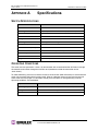
Appendix A: Specifications ...............................................................................64
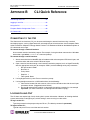
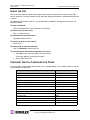
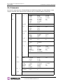
Appendix B: CLI Quick Reference ....................................................................65
Appendix C: Event Messages ........................................................................... 68
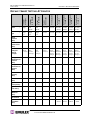
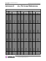
Appendix D: AL_PA Cross References ............................................................ 70
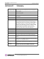
Appendix E: Glossary ........................................................................................71
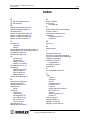
Index .................................................................................................... 72

EMULEX MODEL 375 SAN STORAGE SWITCH
USER’S GUIDE CHAPTER 1: INTRODUCTION
EMULEX CORPORATION 1
P
ART NUMBER 00041392-002 REV. B
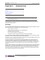
CHAPTER 1INTRODUCTION
This guide is designed to provide users with the necessary information to install and manage the
Emulex® Model 375 SAN Storage Switch for use in Fibre Channel applications in typical entry-level
Storage Area Networks (SANs).
OVERVIEW
The Emulex Model 375 SAN Storage Switch is designed for entry-level Storage Area Networks (SANs),
which provide the following advantages over direct attached storage:
• Greater application availability
• Higher performance between servers and storage devices
• Improved storage asset utilization
• Lower storage management and support costs
• Incremental scalability to keep up with difficult to estimate storage growth
This switch is ideal for storage pooling and consolidation, high-performance shared tape library backup
and recovery, server clustering, and streaming rich media applications.
Enclosed in a 1U, full-rack form factor enclosure, the switch is built around the InSpeed™ SOC 320 and
is controlled by firmware loaded into the on-board Flash.
The switch is designed as a central interconnect following the ANSI FC-AL standard. Devices are
connected to the switch through Small Form-factor Pluggable (SFP) transceivers and cables. Each
attached node has 1 or 2 Gigabits per second (Gb/s) of Fibre Channel bandwidth. The switch operates
at full switching bandwidth that reaches speeds of 4 Gb/s per port and up to 80 Gb/s of aggregate
bandwidth.
Complete switch configuration and management is available through the intuitive, graphical-based Web
Manager interface. A variety of network configurations are easily established using the switch’s Port
Smart Settings, One-Step Zoning, Automatic Trunking, and Load Balancing features. In addition, the
switch features granular change notification management, retained system configuration parameters,
and a Command Line Interface (CLI) for advanced users.
Overview......................................................................1
Features ......................................................................2
InSpeed™ Technology .................................................2
Switch Applications ......................................................3
Note: Important safety, electromagnetic compatibility, and regulatory information is contained in the
Safety & Regulatory Guide
. The installation and use of this product must be in accordance with the
information provided in that guide.

EMULEX MODEL 375 SAN STORAGE SWITCH
USER’S GUIDE CHAPTER 1: INTRODUCTION
EMULEX CORPORATION 2
P
ART NUMBER 00041392-002 REV. B
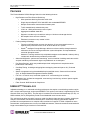
FEATURES
The Emulex Model 375 SAN Storage Switch has the following features:
• High Performance Fibre Channel Switching:
• Wire speed non-blocking Crossbar switch core
• Single 20-port InSpeed™ SOC 320 ASIC with embedded SERDES
• Multiple simultaneous conversations between ports
• Traffic routed directly to destination ports
• 2 Gb/s or 1 Gb/s performance across all ports
• Aggregate bandwidth of 80 Gb/s
• Supports cascades up to 3 switches and up to 126 host and storage devices
• No complex fabric services or buffers
• Effortlessly connects to any vendor’s fabric
• Patent-pending technology:
• Fairness and Prioritization–ensures that devices all have guaranteed access, or
explicitly have prioritized access, over all other devices in a system.
• Stealth
TM
Intelligent Change Manager–delivers maximum stability through automatic
elimination of state and change notification system disruptions and unprecedented
control of disruptive events.
• Automatic Trunking–enables fully-multiplied throughput and bandwidth, failover pathing,
and dynamic load balancing and device prioritization.
• Advanced diagnostics, performance monitoring, and fault isolation including continuous switch
and port monitoring and automatic bypass of problematic or unused ports.
• Port Smart Settings, which are predefined port-level configurations that optimize switch
performance and stability.
• One-Step Zoning, including overlapping/non-overlapping zones with port or AL_PA-based
zoning.
• Switch management using the embedded http-based Web server, Command Line Interface
(CLI), or Simple Network Management Protocol (SNMP).
• Full-rack, 1U size for easy installation (optional 19" rack-mounting kits available).
• Redundant fans and two hot-swappable, auto-sensing, load sharing, universal power supplies
for high availability.
• Fibre Channel ANSI Standards Compliance
INSPEED™ TECHNOLOGY
InSpeed technology is an advanced switching architecture that couples a non-blocking crossbar switch
with a unique switch port logic and per-port SERDES. This results in the industry’s highest density Fibre
Channel switch on a chip (SOC). The port logic is based on Fibre Channel-Arbitrated Loop (FC-AL), an
ANSI standard (X3T11) designed to provide shared bandwidth over low-cost media.
This architecture enables the switch’s router to send data directly from one port to another, allowing for
multiple, simultaneous conversations between ports—effectively multiplying bandwidth. InSpeed
provides the same performance as complex fabric switches that support FC-SW2. InSpeed can even
exceed fabric switch performance in entry-level SAN environments, where the overhead associated with
longer name addressing and services is not beneficial.

EMULEX MODEL 375 SAN STORAGE SWITCH
USER’S GUIDE CHAPTER 1: INTRODUCTION
EMULEX CORPORATION 3
P
ART NUMBER 00041392-002 REV. B
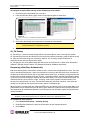
SWITCH APPLICATIONS
The Emulex Model 375 SAN Storage Switch is ideal for consolidation and shared storage pooling, high-
performance shared tape library backup and recovery, server clustering, and streaming rich media
applications. The following sections provide examples of these applications.
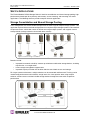
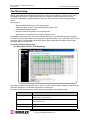
Storage Consolidation and Shared Storage Pooling
In this configuration, the switch enables multiple hosts to share single or multiple storage systems. This
application replaces direct-attached configurations that require multiple storage systems to be attached
to separate servers, which often results in difficult to manage multiple systems and trapped, unused
storage islands (storage cannot be shared with other servers).
Benefits include:
• Improved incremental scalability–connect up to 20 hosts and/or other storage devices, including
tape libraries, to a single switch.
• Lower storage management support costs.
• Improved capacity utilization that enables effective use of both servers and storage.
For larger system environments, multiple switches can be connected and Automatic Trunking can be
used to keep performance and availability at high levels. As a best practice when using multiple
switches, connect servers and their related storage devices through the same switch to optimize
performance.
Figure 1-1: Before storage consolidation...
Figure 1-1: and after storage consolidation.
Figure 1-2: Multiple switch storage consolidation diagram

EMULEX MODEL 375 SAN STORAGE SWITCH
USER’S GUIDE CHAPTER 1: INTRODUCTION
EMULEX CORPORATION 4
P
ART NUMBER 00041392-002 REV. B
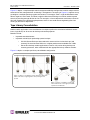
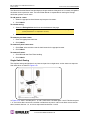
Figure 1-2 depicts a sample multiple switch storage consolidation configuration in which multiple servers
communicate with storage devices and zoning is incorporated. The zoning in Figure 1-2 might be set up
to configure a multiple operating system environment. For example, Zone 1 might be Windows-based,
Zone 2 might be Linux-based, and Zone 3 might be Unix-based. Zoning can also be used to improve
security by masking storage devices or files. For example, a finance department could secure financial
files from viewing by the engineering department, which in turn could secure engineering files from
viewing by the finance department.
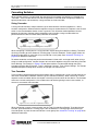
Tape Library Consolidation
Another switch application is the consolidation of multiple tape libraries attached to individual servers
into a single library for all servers for backup and restore purposes.
Benefits include:
• Improved cost effectiveness.
• Improved availability for performing system backups:
• Off-LAN System Backups often reduce the amount of time it takes backups (and
recovery) to occur because SANs run at higher performance bandwidth than LANs.
• Server-less backups enable applications to remain fully active during backup and
recovery processes, when combined with the appropriate backup software solution.
Figure 1-3 depicts a sample tape library consolidation configuration.
Figure 1-3: Before consolidation, backup and restore data must
travel on the LAN, congesting traffic and operating at slow
speeds.
Figure 1-3: After consolidation, backup and
restore data travels on the high speed SAN
separate from LAN traffic.

EMULEX MODEL 375 SAN STORAGE SWITCH
USER’S GUIDE CHAPTER 1: INTRODUCTION
EMULEX CORPORATION 5
P
ART NUMBER 00041392-002 REV. B
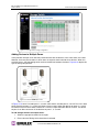
Rich Media
For rich media applications, the switch provides improved storage and file sharing from a single storage
pool for multiple workstations.
Figure 1-4 depicts a sample rich media configuration.
Server Clustering
In this configuration, the switch helps deliver improved application availability when combined with a
server clustering software solution, like Microsoft Cluster Server or Veritas Cluster Server. This prevents
system downtime in case of failure to one of the application servers.
Figure 1-5 depicts a sample server clustering configuration.
Figure 1-4: Rich media diagram
Figure 1-5: Server clustering diagram

EMULEX MODEL 375 SAN STORAGE SWITCH
USER’S GUIDE CHAPTER 2: SWITCH INSTALLATION
EMULEX CORPORATION 6
P
ART NUMBER 00041392-002 REV. B
CHAPTER 2SWITCH INSTALLATION
INSTALLATION PREPARATION
After receiving the switch, perform the following steps to ensure that the switch and other contents
arrived safely.
To unpack the switch:
1. Inspect the outer shipping container for any damage that may have occurred in shipping. Report
any sign of damage to the appropriate shipping agency.
2. Remove the switch and cables from the shipping container; save the shipping container, foam,
and antistatic bags—returning the switch in any other container is not advised.
Make sure the following parts are included:
• Switch unit
• RS-232 null-modem serial cable
• Power cables (2)
• Self-adhesive pads (4)
• Retention clips (2), screws (4), and washers (4) for securing the power cords to the
switch.
• Quick Install Card
• Product Release Notes
• Safety and Regulatory Guide
• Additional documentation, including warranty information and the End User License
Agreement.
3. Inspect the switch thoroughly. (If any signs of damage are seen, notify a sales representative
and/or the shipping agency.)
Installation Preparation ................................................6
Switch Installation ........................................................7
Switch LEDs ................................................................9
SFP Compatibility ......................................................12
Booting the Switch and SAN ......................................13
Power Supply/Fan Module Replacement ...................14

EMULEX MODEL 375 SAN STORAGE SWITCH
USER’S GUIDE CHAPTER 2: SWITCH INSTALLATION
EMULEX CORPORATION 7
P
ART NUMBER 00041392-002 REV. B
SWITCH INSTALLATION
The switch can be installed in a rack or placed on a desktop.
Rack Installation
Installing the switch in an equipment rack requires an optional rack mount kit (sold separately). There
are two kit variations currently available:
• 24-inch Full Rack Mount Kit (Part Number 00651382), which supports equipment rack depths
from 24 to 29.75 inches.
• 30-inch Full Rack Mount Kit (Part Number 00651383), which supports equipment rack depths
from 30 to 36 inches.
The rack mount kit includes all the necessary hardware and installation instructions for properly
installing a switch into an equipment rack. Contact a sales representative for more information or
assistance in purchasing a kit.
UL Guidelines for Mounting Equipment in a Rack
When installing equipment in a rack, give careful consideration to the following factors:
• The operating ambient temperature of rack-mounted equipment must not exceed the maximum
rated ambient temperature, which is indicated in this installation guide. (See “Operating
Conditions” on page 64.)
• The air flow clearances specified in this installation guide must be maintained within the rack.
(See “Operating Conditions” on page 64.)
• The AC supply circuit for rack-mounted equipment must be capable of supplying the total current
specified on all the labels of the rack-mounted equipment.
• All AC power supply connections must be properly earthed. To ensure the integrity of the earth
connection, special attention must be given to connections that are not directly connected to the
branch circuit (for example, power strips).
• The rack-mounting hardware has been carefully selected to properly support the equipment.
Any alternate rack-mounting hardware must provide equal or superior support.
Desktop Installation
To place the switch on a desktop:
1. Turn the switch upside down so the case bottom is facing up.
2. Install a self-adhesive pad (included) on each corner of the switch bottom approximately 1 inch
from each side (prevents surface damage).
3. Turn the switch right-side up so the case bottom is facing down and place the switch on a stable
table or platform.
For information on environmental requirements, see “Operating Conditions” on page 64.
Note: Important safety, electromagnetic compatibility, and regulatory information is
contained in the
Safety & Regulatory Guide
. The installation and use of this product
must be in accordance with the information given in that guide.

EMULEX MODEL 375 SAN STORAGE SWITCH
USER’S GUIDE CHAPTER 2: SWITCH INSTALLATION
EMULEX CORPORATION 8
P
ART NUMBER 00041392-002 REV. B
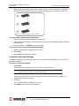
Installing the Retention Clips (optional)
The switch ships with two, optional retention clips to secure the power cords in each power supply/fan
module’s power receptacle. Screws (4) and washers (4) are provided for the clips.
To install the retention clip:
1. Secure the retention clip to the switch by aligning the retention clip with the two screw holes
located to the left and the right of the module’s power receptacle. The retention clip mounting
loops should be facing downward.
2. Place the washer on the screw prior to inserting the screw through the retention clip’s mounting
loop.
3. Using a screwdriver, tighten the screws to secure the retention clip to the power supply/fan
module.
To insert the power cord with the retention clip in place:
1. Insert the power cord plug into the module’s power receptacle. The plug must initially be inserted
into the receptacle at an angle to avoid the retention clip.
2. Once the power cord plug is firmly inserted in the module’s power receptacle, the retention clip
fastens over the end of the power cord plug to secure it in the power receptacle.
To remove the power cord with the retention clip in place:
Press down on the retention clip while removing the power cord from the module’s power receptacle.

EMULEX MODEL 375 SAN STORAGE SWITCH
USER’S GUIDE CHAPTER 2: SWITCH INSTALLATION
EMULEX CORPORATION 9
P
ART NUMBER 00041392-002 REV. B
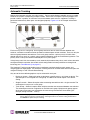
SWITCH LEDS
The switch incorporates four sets of Light-Emitting Diodes (LEDs) to indicate ethernet, switch, port, and
power supply/fan module status:
1. Ethernet LEDs – two separate LEDs indicating the network connection status.
2. System LEDs – four separate LEDs indicating the switch’s status.
3. Port LEDs – two LEDs per port indicating the port’s status.
4. Power Supply/Fan LED – a separate LED for each power supply/fan module indicating the
power supply/fan module’s status.
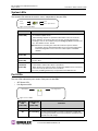
Ethernet LEDs
The Ethernet LEDs indicate the network connection status:
Ethernet LEDs Indication
Ethernet Activity
(green LED)
• When flashing, the ethernet port is receiving data.
• When flashing rapidly, the traffic level is high.
Ethernet Link
(green LED)
When lit, the switch is connected to an operational ethernet.
Figure 2-1: Switch View Depicting Ethernet, Port, and System LEDs
Port LEDs
Ethernet LEDs
System LEDs
Figure 2-2: Switch View Depicting Power Supply/Fan LED
Power Supply/Fan LED
Power Supply/Fan LED
Figure 2-3: Ethernet LEDs
Ethernet Activity
Ethernet Link

EMULEX MODEL 375 SAN STORAGE SWITCH
USER’S GUIDE CHAPTER 2: SWITCH INSTALLATION
EMULEX CORPORATION 10
P
ART NUMBER 00041392-002 REV. B
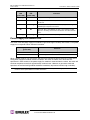
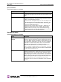
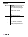
System LEDs
The System LEDs indicate the switch’s status, independent of the port LEDs.
Port LEDs
The Port LEDs indicate the port’s status. Each port has two LEDs:
• SFP Status LED
• Port Bypassed LED
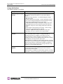
System LEDs Indication
Fault
(yellow LED)
• When lit, one or more of the ports has failed or the internal temperature has
exceeded acceptable levels.
• When flashing, all ports are operational but another error has occurred.
Errors appear in an event log. The level of error severity that will cause
flashing to start can be controlled using the config sys fault command in the
CLI. The default is level 3, Critical.
Note: Whether lit or flashing, the switch will continue to operate. Switch
functionality may be impaired depending on the event that triggered the
Fault LED. Regardless of the cause, the switch requires immediate
attention.
Power
(green LED)
When lit, the switch is plugged in and the internal power supplies are functional.
2 Gb/s
(green LED)
When lit, the switch is set to operate at a speed of 2 Gb/s. When off, the switch
is set to 1 Gb/s.
Switch
Operational
(green LED)
• When lit, indicates that the switch has completed initialization for ports with
inserted SFPs and that the switch is operational.
• When flashing, the switch has been configured for multiple zones, and one or
more zones are up with at least one zone down.
If no zones (excluding hard zones) are operational, the LED turns off.
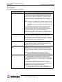
SFP Status
LED
(green LED)
Port Bypassed
LED
(yellow LED)
Indication
Off Off Normal port operational status when an SFP is not installed.
Off On or Flashing The port is bypassed due to a faulty or improperly seated SFP.
After fixing this problem, power may need to be cycled before the
LED indication will change.
Figure 2-4: System LEDs
Power
Switch Operational
Fault
2 Gb/s
Figure 2-5: Port LEDs
SFP Status
Port Bypassed

EMULEX MODEL 375 SAN STORAGE SWITCH
USER’S GUIDE CHAPTER 2: SWITCH INSTALLATION
EMULEX CORPORATION 11
P
ART NUMBER 00041392-002 REV. B
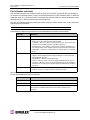
Power Supply/Fan Module LED
The switch uses two power supply/fan modules to guarantee high availability with failover. Each power
supply has a separate LED to indicate its condition.
When a power supply or fan fault occurs, the switch will continue to operate normally as long as the
faulty power supply/fan module remains installed in the switch and there are at least two fans
operational in each module. If the power supply/fan module is removed from the switch, the switch will
continue to operate normally for approximately 20-30 minutes. However, to guarantee continued
operation, the malfunctioning module should be immediately replaced to maintain high availability.
Flashing Off Activity. Data is being transferred between the port and device.
On Off Normal operation but no activity. Port and device are fully
operational.
On Flashing Manually bypassed. A port can be manually bypassed using the
Web Manager’s Bypass Port feature.
On On Bypassed. SFP is installed but the port is not receiving a valid
signal or is receiving an F8 Failure notification from the attached
device.
Flashing Flashing Beaconing. This is set manually using the Web Manager or CLI.
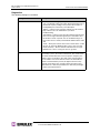
Power Supply/Fan Module LED
(green LED)
Indication
On No faults exist and AC power is supplied to the module.
Off A power supply or fan fault has occurred in the module.
Note: Keeping spare power supply/fan modules (Part Number 601319) in stock is highly recommended.
Contact a sales representative for further information.
SFP Status
LED
(green LED)
Port Bypassed
LED
(yellow LED)
Indication

EMULEX MODEL 375 SAN STORAGE SWITCH
USER’S GUIDE CHAPTER 2: SWITCH INSTALLATION
EMULEX CORPORATION 12
P
ART NUMBER 00041392-002 REV. B
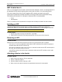
SFP COMPATIBILITY
SFPs are “hot-pluggable” into the switch, which allows host computers, servers, and storage devices to
be added dynamically without requiring power removal from the switch or any connected devices.
The switch supports Small Form-Factor Pluggable (SFP) modules that comply with the SFP
specification as produced by the MSA consortium and have passed Emulex’s qualification testing.
The following manufacturers of 1-2Gb optical, shortwave SFPs are recommended:
•Finisar
•JDS Uniphase
Contact a customer service representative to request the certified part numbers for these vendors.
Installing an SFP
If the Change Notification on Insertion policy is enabled, plugging an SFP into the switch will
automatically send an F7 Initialization notification to indicate the device is ready to begin initialization.
To insert an SFP:
1. Remove dust covers or plugs from the SFPs, if provided.
2. Slide the SFP into the port, ensuring correct polarity, until the latch clicks into place.
Removing an SFP
To extract an SFP:
Determine what kind of extraction mechanism the SFP has and remove the SFP as follows:
If the SFP has a removal tag,
remove the cable from the SFP and then pull the removal tag outward
and toward the side of the SFP with the tag.
If the SFP has a small plastic slider
on the top or bottom
, remove the cable from the SFP and then push in
the slider and hold while pulling out the SFP.
If the SFP has a bale (small metal clasp)
, remove the cable from the SFP and then unlatch, pivot,
and pull the bale.
Attaching a Device to the Switch
To attach a device:
1. Make sure that the device is FC-AL compatible.
2. Attach a cable to the device.
3. Attach the other end of the cable to an SFP.
4. Make sure that the device and switch are operational and set to the same speed.
Caution: Forcing an SFP into a port may damage the SFP and/or port.

EMULEX MODEL 375 SAN STORAGE SWITCH
USER’S GUIDE CHAPTER 2: SWITCH INSTALLATION
EMULEX CORPORATION 13
P
ART NUMBER 00041392-002 REV. B
BOOTING THE SWITCH AND SAN
The following procedure is recommended when booting the switch and SAN. Before powering on the
switch and SAN, read the Release Notes, included with the switch contents, to determine any
modifications that may be required for a specific installation.
To boot the switch and SAN:
1. Power on the storage devices (such as JBODs, tape libraries, and RAIDs).
2. Insert the plug end of the switch’s power cord to a properly grounded power source.
3. Insert the power cord’s IEC connector end into the switch’s power receptacle.
The switch powers on and runs Power-On Self-Test (POST) diagnostics to verify the
fundamental integrity of the switch ports. All switch LEDs turn on (LEDs illuminate). Then,
excluding the Ethernet Link, Power Supply/Fan Module, and Power LEDs, the LEDs turn off
(LEDs extinguish). Once the switch is operational, the LEDs display current status as described
in “Switch LEDs” on page 9.
4. Power on any other switches connected to the SAN.
5. For certain applications, switch configuration must be completed before continuing with the next
step. For information regarding switch configuration, see Chapter 3: Switch Management.
6. After all switches have initialized, power on the hosts.
The network initializes.
7. Check all port LEDs.
The SAN should be fully operational at this point. However, it is appropriate to ensure that
proper discovery has taken place and all required devices are participating in the network. Some
host bus adapters may provide this level of functionality or it might be resident in the application
software on the host operating system.
Note: The power cord’s IEC connector plug serves as the switch’s disconnect device. To
cycle power to the switch, remove and reconnect the switch’s power cord.
Note: FC-AL compatible nodes must perform initialization procedures upon power-up in
order to function properly. It is the responsibility of the Fibre Channel driver software
on FC-AL nodes to perform this initialization.

EMULEX MODEL 375 SAN STORAGE SWITCH
USER’S GUIDE CHAPTER 2: SWITCH INSTALLATION
EMULEX CORPORATION 14
P
ART NUMBER 00041392-002 REV. B
POWER SUPPLY/FAN MODULE REPLACEMENT
The Emulex® Model 375 SAN Storage Switch has hot-swappable power supply/fan modules for high
availability. A power supply/fan module consists of an individual power supply and a fan bank consisting
of three fans.
The switch can run on one functioning power supply/fan module indefinitely, as long as the faulty power
supply/fan module remains installed in the switch and there are at least two fans operational in each
module’s fan bank. If the power supply/fan module is removed from the switch, the switch will continue
to operate normally for approximately 20-30 minutes. Non-functional modules should be immediately
replaced to maintain high availability.
To remove an old power supply/fan module:
1. Have the new power supply/fan module close to the switch for quick insertion. (This step
ensures that the procedure takes no longer than necessary—the switch can only operate with
one power supply/fan module installed for approximately 20-30 minutes.)
2. Unplug the power cord from the faulty module’s power receptacle.
3. Slide the safety latch over the power receptacle to expose the thumb screw.
4. Loosen the two thumb screws. No tools are required.
5. Pull the unscrewed power supply/fan module out of the switch’s module bay using the module’s
handle.
To insert a new power supply/fan module:
1. Align the power supply/fan module with the module bay opening. Ensure that the warning label
is facing upwards on the module.
2. Carefully slide the module into the opening. Ensure that the module is seated firmly in the
module bay (the module should be flush with the switch’s face).
3. Tighten the two thumb screws. No tools are required.
4. Slide the safety latch over the thumb screw (uncovering the power receptacle).
5. Plug the power cord into the module’s module power receptacle.
Note: Keeping spare power supply/fan modules (Part Number 601319) in stock is highly
recommended. Contact a sales representative for further information.
Note: The alternate power supply/fan module should remain powered on while the faulty
module is removed and replaced to guarantee switch availability.
WARNING
To avoid an electrical hazard, never apply power to the power supply/fan module while the module is
removed from the switch.
Note: When using a screwdriver to tighten the thumb screws, ensure that the thumb screws
are secure but not overtightened. Overtightening the thumb screws may damage the
screws or the module.

EMULEX MODEL 375 SAN STORAGE SWITCH
USER’S GUIDE CHAPTER 3: SWITCH MANAGEMENT
EMULEX CORPORATION 15
P
ART NUMBER 00041392-002 REV. B
CHAPTER 3SWITCH MANAGEMENT
This chapter is divided into three sections providing information on how to manage and monitor the
switch:
• Getting Started – Describes how to configure the network interface, use the Web Manager, and
perform a basic initial setup of the switch.
• Managing the Switch - Describes how to configure the switch and port settings, manage
firmware versions and configuration files, set switch thresholds, and configure One-Step Zoning,
Automatic Trunking, and Load Balancing.
• Monitoring the Switch – Describes how to view switch information, the event log, port
information, and port diagnostics.
The switch incorporates two distinct interfaces for managing and monitoring purposes:
• The Web Manager interface provides an intuitive graphical user interface that enables users to
quickly check switch status or modify switch settings in a visual environment.
• The Command Line Interface (CLI) provides flexibility and additional functionality for advanced
users.
Both of these interfaces provide nearly identical functionality; however, for the purposes of this guide,
the Web Manager interface is used for switch and port configuration unless otherwise noted.
For a list of CLI commands, see Appendix B: CLI Quick Reference on page 65. For additional
information on the CLI, see the
Emulex® or InSpeed™ Storage Switch Products’ CLI Reference Guide
.
Getting Started...........................................................16
Managing the Switch..................................................21
Monitoring the Switch.................................................49

EMULEX MODEL 375 SAN STORAGE SWITCH
USER’S GUIDE CHAPTER 3: SWITCH MANAGEMENT
EMULEX CORPORATION 16
P
ART NUMBER 00041392-002 REV. B
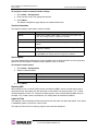
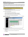
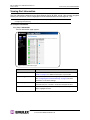
GETTING STARTED
This section explains how to configure the switch’s ethernet network settings prior to using the Web
Manager. Once the switch’s network settings are configured, use the Web Manager to perform a quick
switch setup.
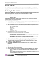
Configuring the Network Interface
Before using the Web Manager, ensure that the switch’s ethernet network parameter settings are correct
for the network configuration. The switch ships with the following default IP settings:
• IP Address: 169.254.10.10
• Netmask: 255.255.0.0
• Gateway: 0.0.0.0
To adjust these settings to open the Web Manager, connect to the switch using the provided serial
interface cable and follow the instructions below.
To connect through a serial interface:
1. Attach one end of the included RS-232 null modem cable to the computer’s DB-9 serial port and
attach the other end to the switch’s DB-9 serial port.
2. Open a terminal session through a serial terminal emulation program (such as HyperTerminal®)
with the appropriate serial port (for example, COM1) and the following serial port parameters:
• Bits per second: 19200
• Data bits: 8
• Parity: None
• Stop bits: 1
• Flow control: None
3. If using HyperTerminal, press E
NTER to receive a prompt.
If using the tip command on a UNIX workstation, do the following:
a. View the /etc/remote file and create an alias similar to Hardware but with the serial port
parameters above. (Suggested name: Switch)
b. Use the tip command to establish a connection through the created alias, for example
tip switch. (For more information, see the tip command Manual page.)
4. Type the password at the prompt and press E
NTER. (The default password is password.)
5. From the serial terminal emulation program, type config network ip and press E
NTER.
The switch’s current IP parameters are displayed with a prompt for entering the IP address.
6. Change the IP address and press E
NTER.
7. Use the mask and gateway commands to change the subnet mask and default gateway
respectively.
8. Type save and press E
NTER.
9. Type root reset and press E
NTER.
10. Type y and press E
NTER to reset the switch.
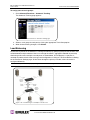
11. Attach the computer to the switch’s 10/100 ethernet connector by doing one of the following:
• Attach an ethernet RJ-45 cross-over cable directly between the computer and the
switch.
• Attach two ethernet RJ-45 twisted pair cables from the computer and the switch into an
operational ethernet patch panel or hub.

EMULEX MODEL 375 SAN STORAGE SWITCH
USER’S GUIDE CHAPTER 3: SWITCH MANAGEMENT
EMULEX CORPORATION 17
P
ART NUMBER 00041392-002 REV. B
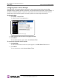
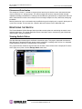
Connecting to the Web Manager
The Web Manager displays current port utilization and health, enables easy to use Port Smart Settings
and One-Step Zoning, and several additional features discussed later in this chapter.
To connect to the Web Manager:
1. Ensure that the workstation has access to the network on which the switch is connected.
2. Open Microsoft Internet Explorer.
3. In the address bar, type the switch’s DNS name or IP address and press E
NTER.
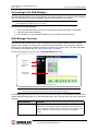
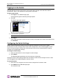
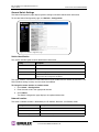
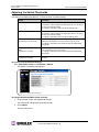
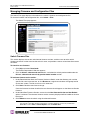
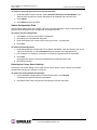
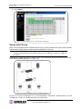
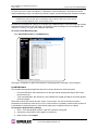
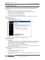
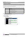
Web Manager Overview
The Web Manager enables users to view and configure switch and port settings using an intuitive,
graphical user interface. The main page is the Switch Information page. This page displays general
switch status and continually refreshes to display the most current switch status. For more information
on the Switch Information page, see “Switch Information” on page 50.
To return to this page at any time, click the Storage Switch menu item.
The Web Manager interface consists of a series of command buttons, an expandable navigation menu,
and the displayed information area. The command buttons and navigation menu are always present on
the page.
Note: The Web Manager supports Microsoft Internet Explorer for Windows version 5.5 or later and
Internet Explorer for Apple version 5.2 or later.
Note: The Web browser’s appearance and information depends on the switch’s active firmware
version and may change without notice in subsequent firmware versions.
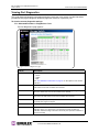
Command Button Description
Submit Saves any changes made to the switch configuration. This button is
disabled until a configuration setting is changed or new information is
entered. This button appears green to notify the user of a change to the
switch configuration. Click this button to accept the configuration
change.
Figure 3-1: Web Manager interface
Navigation
Menu
Command
buttons
Current page
information
Page is loading ...
Page is loading ...
Page is loading ...
Page is loading ...
Page is loading ...
Page is loading ...
Page is loading ...
Page is loading ...
Page is loading ...
Page is loading ...
Page is loading ...
Page is loading ...
Page is loading ...
Page is loading ...
Page is loading ...
Page is loading ...
Page is loading ...
Page is loading ...
Page is loading ...
Page is loading ...
Page is loading ...
Page is loading ...
Page is loading ...
Page is loading ...
Page is loading ...
Page is loading ...
Page is loading ...
Page is loading ...
Page is loading ...
Page is loading ...
Page is loading ...
Page is loading ...
Page is loading ...
Page is loading ...
Page is loading ...
Page is loading ...
Page is loading ...
Page is loading ...
Page is loading ...
Page is loading ...
Page is loading ...
Page is loading ...
Page is loading ...
Page is loading ...
Page is loading ...
Page is loading ...
Page is loading ...
Page is loading ...
Page is loading ...
Page is loading ...
Page is loading ...
Page is loading ...
Page is loading ...
Page is loading ...
Page is loading ...
Page is loading ...
Page is loading ...
-
 1
1
-
 2
2
-
 3
3
-
 4
4
-
 5
5
-
 6
6
-
 7
7
-
 8
8
-
 9
9
-
 10
10
-
 11
11
-
 12
12
-
 13
13
-
 14
14
-
 15
15
-
 16
16
-
 17
17
-
 18
18
-
 19
19
-
 20
20
-
 21
21
-
 22
22
-
 23
23
-
 24
24
-
 25
25
-
 26
26
-
 27
27
-
 28
28
-
 29
29
-
 30
30
-
 31
31
-
 32
32
-
 33
33
-
 34
34
-
 35
35
-
 36
36
-
 37
37
-
 38
38
-
 39
39
-
 40
40
-
 41
41
-
 42
42
-
 43
43
-
 44
44
-
 45
45
-
 46
46
-
 47
47
-
 48
48
-
 49
49
-
 50
50
-
 51
51
-
 52
52
-
 53
53
-
 54
54
-
 55
55
-
 56
56
-
 57
57
-
 58
58
-
 59
59
-
 60
60
-
 61
61
-
 62
62
-
 63
63
-
 64
64
-
 65
65
-
 66
66
-
 67
67
-
 68
68
-
 69
69
-
 70
70
-
 71
71
-
 72
72
-
 73
73
-
 74
74
-
 75
75
-
 76
76
-
 77
77


Vixel Model 375 User manual
- Category
- Network switches
- Type
- User manual
- This manual is also suitable for
Ask a question and I''ll find the answer in the document
Finding information in a document is now easier with AI
Related papers

Other documents
-
Emulex InSpeed 350 User manual
-
-
-
-
-
Lenovo IBM TS3100 User manual
-
Bull Storage Area Network (SAN) Installation guide
-
-
Lenovo System x3550 M5 User manual
-
Lenovo System x3850 X5 User manual