Page is loading ...

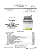
OPERATOR’S MANUAL
FRYMASTER BIPH55/MPH55 SERIES
GAS FRYER
TABLE OF CONTENTS
WARRANTY STATEMENT..................................................................................................Page i
INTRODUCTION..................................................................................................................Page 1-1
INSTALLATION INSTRUCTIONS .......................................................................................Page 2-1
OPERATING INSTRUCTIONS ............................................................................................Page 3-1
OPERATING THE BUILT IN FILTRATION SYSTEM ..........................................................Page 4-1
PREVENTIVE MAINTENANCE............................................................................................Page 5-1
OPERATOR TROUBLESHOOTING....................................................................................Page 6-1
Frymaster, L.L.C. 8700 Line Avenue 71106, 5489 Campus Drive 71129
P.O. Box 51000, Shreveport, Louisiana 71135-1000
TEL 318-865-1711 FAX (Parts) 318-219-7140 (Tech Support) 318-219-7135
PRINTED IN THE UNITED STATES SERVICE HOTLINE OCTOBER 2005
1-800-24-FRYER
www.frymaster.com
Email: [email protected] *8196087*
FOR YOUR SAFETY
Do Not Store or use gasoline or other
flammable vapors and liquids in the
vicinity of this or any other appliance.
This equipment chapter is to be
installed in the Fryer Section of the
Equipment Manual.
MANUFACTURED
BY
P.O. BOX 51000
SHREVEPORT, LOUISIANA 71135-1000
PHONE: 1-318-865-1711
TOLL FREE: 1-800-551-8633
1-800-24 FRYER
FAX: 1-318-219-7135

NOTICE
IF, DURING THE WARRANTY PERIOD, THE CUSTOMER USES A PART FOR THIS ENODIS
EQUIPMENT OTHER THAN AN UNMODIFIED NEW OR RECYCLED PART PURCHASED DIRECTLY
FROM FRYMASTER DEAN, OR ANY OF ITS AUTHORIZED SERVICE CENTERS, AND/OR THE PART
BEING USED IS MODIFIED FROM ITS ORIGINAL CONFIGURATION, THIS WARRANTY WILL BE
VOID. FURTHER, FRYMASTER DEAN AND ITS AFFILIATES WILL NOT BE LIABLE FOR ANY
CLAIMS, DAMAGES OR EXPENSES INCURRED BY THE CUSTOMER WHICH ARISE DIRECTLY OR
INDIRECTLY, IN WHOLE OR IN PART, DUE TO THE INSTALLATION OF ANY MODIFIED PART
AND/OR PART RECEIVED FROM AN UNAUTHORIZED SERVICE CENTER.
NOTICE
This appliance is intended for professional use only and is to be operated by qualified personnel
only. A Frymaster DEAN Factory Authorized Service Center (FASC) or other qualified professional
should perform installation, maintenance, and repairs. Installation, maintenance, or repairs by
unqualified personnel may void the manufacturer’s warranty. See Chapter 1 of this manual for
definitions of qualified personnel.
NOTICE
This equipment must be installed in accordance with the appropriate national and local codes of
the country and/or region in which the appliance is installed. See NATIONAL CODE
REQUIREMENTS in Chapter 2 of this manual for specifics.
NOTICE TO U.S. CUSTOMERS
This equipment is to be installed in compliance with the basic plumbing code of the Building
Officials and Code Administrators International, Inc. (BOCA) and the Food Service Sanitation
Manual of the U.S. Food and Drug Administration.
NOTICE
Drawings and photos used in this manual are intended to illustrate operational, cleaning and
technical procedures and may not conform to onsite management operational procedures.
NOTICE TO OWNERS OF UNITS EQUIPPED WITH COMPUTERS
U.S.
This device complies with Part 15 of the FCC rules. Operation is subject to the following two
conditions: 1) This device may not cause harmful interference, and 2) This device must accept
any interference received, including interference that may cause undesired operation. While
this device is a verified Class A device, it has been shown to meet the Class B limits.
CANADA
This digital apparatus does not exceed the Class A or B limits for radio noise emissions as set
out by the ICES-003 standard of the Canadian Department of Communications.
Cet appareil numerique n’emet pas de bruits radioelectriques depassany les limites de classe A
et B prescrites dans la norme NMB-003 edictee par le Ministre des Communcations du Canada.
DANGER
Improper installation, adjustment, maintenance or service, and unauthorized alterations or
modifications can cause property damage, injury, or death. Read the installation, operating,
and service instructions thoroughly before installing or servicing this equipment. Only qualified
service personnel may convert this appliance to use a gas other than that for which it was
originally configured.

DANGER
No structural material on the fryer should be altered or removed to accommodate placement of
the fryer under a hood. Questions? Call the Frymaster Dean Service Hotline at 1-800-551-8633.
DANGER
Adequate means must be provided to limit the movement of this appliance without depending
upon the gas line connection. All fryers equipped with casters must be stabilized by installing
restraining chains. If a flexible gas line is used, an additional restraining cable must be
connected at all times when the fryer is in use.
DANGER
The front ledge of the fryer is not a step! Do not stand on the fryer. Serious injury can result
from slips or contact with the hot oil.
DANGER
Do not store or use gasoline or other flammable liquids or vapors in the vicinity of this or any
other appliance.
DANGER
Instructions to be followed in the event the operator smells gas or otherwise detects a gas leak
must be posted in a prominent location. This information can be obtained from the local gas
company or gas supplier.
DANGER
This product contains chemicals known to the state of California to cause cancer and/or birth
defects or other reproductive harm.
Operation, installation, and servicing of this product could expose you to airborne particles of
glasswool or ceramic fibers, crystalline silica, and/or carbon monoxide. Inhalation of airborne
particles of glasswool or ceramic fibers is known to the State of California to cause cancer.
Inhalation of carbon monoxide is known to the State of California to cause birth defects or other
reproductive harm.
DANGER
The crumb tray in fryers equipped with a filter system must be emptied into a fireproof container
at the end of frying operations each day. Some food particles can spontaneously combust if left
soaking in certain shortening material.
WARNING
Do not bang fry baskets or other utensils on the fryer’s joiner strip. The strip is present to seal
the joint between the fry vessels. Banging fry baskets on the strip to dislodge shortening will
distort the strip, adversely affecting its fit. It is designed for a tight fit and should only be
removed for cleaning.
WARNING
To ensure the safe and efficient operation of the fryer and hood, the electrical plug for the 120-
volt line, which powers the hood, must be fully engaged and locked in its pin and sleeve socket.
NOTICE
The Commonwealth of Massachusetts requires any and all gas products to be installed by a
licensed plumber or pipe fitter.

i
WARRANTY STATEMENT
Frymaster, L.L.C. makes the following limited warranties to the original purchaser only for this
equipment and replacement parts:
A. WARRANTY PROVISIONS - FRYERS
1. Frymaster L.L.C. warrants all components against defects in material and workmanship for a
period of one year.
2. All parts, with the exception of the frypot, heating elements and fuses, are warranted for one year
after installation date of fryer.
3. If any parts, except fuses and filter O-rings, become defective during the first year after
installation date, Frymaster will also pay straight-time labor costs to replace the part, plus up to
100 miles/160 km of travel (50 miles/80 km each way).
B. WARRANTY PROVISIONS - FRYPOTS
(Applies to fryers manufactured after December 1, 2003, only.)
1. Frymaster warrants the frypot assembly for ten years parts and labor. Components attached to
the frypot, such as the high-limit, probe, gaskets, seals, ignitors and related fasteners, are also
covered by the ten-year warranty if replacement is necessitated by the frypot replacement.
Components that are not part of the frypot assembly, such as the blower, gas valve, micro
switches, doors and cabinetry are not covered by the frypot warranty. If the frypot is found to be
defective, Frymaster will replace the frypot, allowing up to the maximum time per the Frymaster
time allowance chart hours of straight-time labor plus up to 100 miles/160 km of travel (50
miles/80 km each way) to change the frypot.
2. This warranty is limited to fryers operating on natural or propane (LP) gas. Fryers that operate
on manufactured gas (also known as town gas or high-hydrogen gas) have a lifetime frypot
warranty, parts only.
C. WARRANTY PROVISIONS – COMBUSTION CHAMBERS
(Applies to fryers installed on or after November 1, 1994, only.)
1. Frymaster L.L.C. warrants the combustion chambers against defective material or workmanship
for a period of ten years from the original installation date, parts and labor.
2. The combustion chamber consists of the infrared burners and the structural components to mount
the burners. This warranty does not cover ancillary components, including the igniter, blower,
high-limit thermostat, and temperature probe.
3. This warranty is limited to fryers operating on natural or propane (LP) gas.

ii
D. WARRANTY PROVISIONS - COOKING COMPUTER
1. Frymaster L.L.C. warrants the M-2000 Cooking Computer against defective material or
workmanship for a period of three years from the original installation date. If the unit fails within
the first year, warranty will cover part and labor. If the part fails the second year, warranty will
cover part only. Labor is charged to the store. The third year, warranty will cover the part at a
reduced cost of $90.00. No labor or handling will be covered.
2. During this warranty period, Frymaster will replace a returned defective cooking computer with a
new or factory rebuilt and functionally operative units.
3. For replacement of defective computers under warranty, call your local Frymaster Authorized
Service Center. All computers replaced under the Frymaster exchange program only carry the
remaining original warranty.
E. PARTS RETURN
All defective in-warranty parts must be returned to a Frymaster Authorized Factory Service Center
within 60 days for credit. After 60 days, no credit will be allowed.
F. WARRANTY EXCLUSIONS
This warranty does not cover equipment that has been damaged due to misuse, abuse, alteration, or
accident such as:
• improper or unauthorized repair (including any frypot which is welded in the field);
• failure to follow proper installation instructions and/or scheduled maintenance procedures as
prescribed in your MRC cards. Proof of scheduled maintenance is required to maintain the warranty;
• improper maintenance;
• damage in shipment;
• abnormal use;
• removal, alteration, or obliteration of either the rating plate or the date code on the heating elements;
• operating the frypot without shortening or other liquid in the frypot;
• no fryer will be warranted under the ten-year program for which a proper start-up form has not been
received.
This warranty also does not cover:
• transportation or travel over 100 miles/160 km (50 miles/80 km each way), or travel over two hours;
• overtime or holiday charges;
• consequential damages (the cost of repairing or replacing other property which is damaged), loss of
time, profits, use or any other incidental damages of any kind.
There are no implied warranties of merchantability or fitness for any particular use or purpose.
This warranty is applicable at the time of this printing and is subject to change.

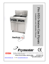
1-1
BIPH55 / MPH55 SERIES GAS FRYER
CHAPTER 1: INTRODUCTION
1.1 General
Read the instructions in this manual thoroughly before attempting to operate this equipment. This
manual covers all configurations of models MPH55 and BIPH55 fryers. Models designated MPH55
do not have built-in filtration systems. Models designated BIPH55 are equipped with FootPrint Pro
built-in filtration systems. The fryers in this model family have most parts in common, and when
discussed as a group, will be referred to as “Pro Series H55” fryers.
Although similar in appearance to the BIH52 McDonald’s fryers, the BIPH55 fryers feature a
significantly different built-in filtration system. The new Euro-Look incorporates rounded topcaps
and large round drains, which ensures that fries and other debris will be washed into the filter pan.
Other features, including the deep cold-zones and easy to clean, open frypots remain essentially
unchanged. All Pro Series H55 Gas fryers come standard with M2000 computer, electronic ignition,
melt cycle, and boil-out mode.
Fryers in this series come in full- or split-vat arrangements, and can be purchased as single units or
in batteries of up to five fryers.
Pro Series H55 high-efficiency gas fryers employ a unique infrared burner system that uses up to
43% less energy to cook the same volume as conventional open-burner fryers.
All Pro Series H55 Gas fryers are of an open-frypot design with no tubes and have a hand-sized
opening into the deep cold zone, which makes cleaning the stainless frypot quick and easy.
Heating is supplied by a pair of infrared burner assemblies mounted on each side of the frypot. A
dedicated blower mounted on the front of the frypot supplies combustion air for the burners. Pro
Series H55 Gas fryers can be configured for natural gas, propane (LP), or manufactured gas, as
required by the customer.
Each frypot is equipped with a temperature probe for precise temperature control.
All fryers in this series require an external source of AC electrical power. Units can be configured
for voltages ranging from 100 VAC to 240 VAC.
BIPH55 and MPH55 fryers are shipped completely assembled. All fryers are shipped with a package
of standard accessories. Each fryer is adjusted, tested, and inspected at the factory before crating for
shipment.
This appliance is only for professional use and shall be used by qualified personnel only, as
defined in Section 1.6.

1-2
1.2 Safety Information
Before attempting to operate your unit, read the instructions in this manual thoroughly. Throughout
this manual, you will find notations enclosed in double-bordered boxes similar to the ones that
follow.
CAUTION
CAUTION boxes contain information about actions or conditions that may cause or result
in a malfunction of your system.
WARNING
WARNING boxes contain information about actions or conditions that may cause or result
in damage to your system, and which may cause your system to malfunction.
DANGER
DANGER boxes contain information about actions or conditions that may cause or result
in injury to personnel, and which may cause damage to your system and/or cause your
system to malfunction.
Your fryer is equipped with automatic safety features:
1. High temperature detection shuts off gas to the burner assembly should the controlling
thermostat fail.
2. A safety switch built into the drain valve on units with filter systems prevents burner ignition
with the drain valve even partially open.
1.3 Computer Information for the M2000 Computers
FCC COMPLIANCE
This equipment has been tested and found to comply with the limits for a Class A digital device, pur-
suant to Part 15 of the FCC rules. While this device is a verified Class A device, it has been shown
to meet the Class B limits. These limits are designed to provide reasonable protection against harm-
ful interference when the equipment is operated in a commercial environment. This equipment
generates, uses and can radiate radio frequency energy and, if not installed and used in accordance
with the instruction manual, may cause harmful interference to radio communications.
Operation of the equipment in a residential area is likely to cause harmful interference in which case
the user will be required to correct the interference at his own expense.
The user is cautioned that any changes or modifications not expressly approved by the party respon-
sible for compliance could void the user's authority to operate the equipment.
If necessary, the user should consult the dealer or an experienced radio and television technician for
additional suggestions.

1-3
The user may find the following booklet prepared by the Federal Communications Commission
helpful: "How to Identify and Resolve Radio-TV Interference Problems". This booklet is available
from the U.S. Government Printing Office, Washington, DC 20402, Stock No. 004-000-00345-4.
1.4 European Community (CE) Specific Information
The European Community (CE) has established certain specific standards regarding equipment of
this type. Whenever a conflict exists between CE and non-CE standards, the information or
instructions concerned are identified by means of shadowed boxes.
1.5 Installation, Operating, and Service Personnel
Operating information for Frymaster equipment has been prepared for use by qualified and/or
authorized personnel only, as defined in Section 1.6. All installation and service on Frymaster
equipment must be performed by qualified, certified, licensed, and/or authorized installation
or service personnel, as defined in Section 1.6.
1.6 Definitions
QUALIFIED AND/OR AUTHORIZED OPERATING PERSONNEL
Qualified/authorized operating personnel are those who have carefully read the information in this
manual and have familiarized themselves with the equipment functions, or who have had previous
experience with the operation of the equipment covered in this manual.
QUALIFIED INSTALLATION PERSONNEL
Qualified installation personnel are individuals, firms, corporations, and/or companies which, either
in person or through a representative, are engaged in and are responsible for the installation of gas-
fired appliances. Qualified personnel must be experienced in such work, be familiar with all gas
precautions involved, and have complied with all requirements of applicable national and local
codes.
QUALIFIED SERVICE PERSONNEL
Qualified service personnel are those who are familiar with Frymaster equipment and who have been
authorized by Frymaster, L.L.C. to perform service on the equipment. All authorized service
personnel are required to be equipped with a complete set of service and parts manuals, and to stock
a minimum amount of parts for Frymaster equipment. A list of Frymaster Factory Authorized
Service Centers (FASC) is included with the fryer when shipped from the factory. Failure to use
qualified service personnel will void the Frymaster warranty on your equipment.

1-4
1.7 Shipping Damage Claim Procedure
Your Frymaster equipment was carefully inspected and packed before leaving the factory. The
transportation company assumes full responsibility for safe delivery upon its acceptance of the
equipment for transport.
What to do if your equipment arrives damaged:
1. File a claim for damages immediately, regardless of the extent of damages.
2. Inspect for and record all visible loss or damage, and ensure that this information is noted on
the freight bill or express receipt and is signed by the person making the delivery.
3. Concealed loss or damage that was unnoticed until the equipment was unpacked should be
recorded and reported to the freight company or carrier immediately upon discovery. A
concealed damage claim must be submitted within 15 days of the date of delivery. Ensure that
the shipping container is retained for inspection.
Frymaster
DOES NOT ASSUME RESPONSIBILITY FOR DAMAGE OR LOSS
INCURRED IN TRANSIT.
1.8 Parts Ordering and Service Information
For non-routine maintenance or repairs, or for service information, contact your local Frymaster
Authorized Service Center (FASC). In order to assist you quickly, the Frymaster Factory
Authorized Service Center (FASC) or Service Department representative requires certain
information about your equipment. Most of this information is printed on a data plate affixed to the
inside of the fryer door. Part numbers are found in the Installation, Operation, Service, and Parts
Manual. Parts orders may be placed directly with your local FASC or distributor. Included with
fryers when shipped from the factory is a list of Frymaster FASCs. If you do not have access to this
list, contact the Frymaster Service Department at 1-800-551-8633 or 1-318-865-1711.
When ordering parts, the following information is required:
Model Number:
Serial Number:
Type of Gas or Voltage:
Item Part Number:
Quantity Needed:

1-5
Service information may be obtained by contacting your local FASC/Distributor. Service may also
be obtained by calling the Frymaster Service Department at 1-800-551-8633 or 1-318-865-1711.
When requesting service, please have the following information ready:
Model Number:
Serial Number:
Type of Gas:
In addition to the model number, serial number, and type of gas, please be prepared to describe the
nature of the problem and have ready any other information that you think may be helpful in solving
your problem.
RETAIN AND STORE THIS MANUAL IN A SAFE PLACE FOR FUTURE USE.

2-1
BIPH55 / MPH55 SERIES GAS FRYER
CHAPTER 2: INSTALLATION INSTRUCTIONS
2.1 General Installation Requirements
Qualified, licensed, and/or authorized installation or service personnel, as defined in Section
1.6 of this manual, should perform all installation and service on Frymaster equipment.
Conversion of this appliance from one type of gas to another should only be performed by
qualified, licensed, and/or authorized installation or service personnel as defined in Section 1.6
of this manual.
Failure to use qualified, licensed, and/or authorized installation or service personnel (as de-
fined in Section 1.6 of this manual) to install, convert to another gas type or otherwise service
this equipment will void the Frymaster warranty and may result in damage to the equipment
or injury to personnel.
Where conflicts exist between instructions and information in this manual and local or na-
tional codes or regulations, installation and operation shall comply with the codes or regula-
tions in force in the country in which the equipment is installed.
DANGER
Building codes prohibit a fryer with its open tank of hot oil being installed beside an
open flame of any type, including those of broilers and ranges.
Upon arrival, inspect the fryer carefully for visible or concealed damage. (See Shipping Damage
Claim Procedure in Section 1.7 of this manual.)
DANGER
Frymaster appliances equipped with legs are for stationary installations. Appliances
fitted with legs must be lifted during movement to avoid damage to the appliance
and bodily injury. For movable installations, optional equipment casters must be
used. Questions? Call 1-800-551-8633.
2.1.1 CLEARANCE AND VENTILATION
The fryer(s) must be installed with a 6” (150 mm) clearance at both sides and back when installed
adjacent to combustible construction; no clearance is required when installed adjacent to
noncombustible construction. A minimum of 24” (600 mm) clearance should be provided at the
front of the fryer.
WARNING
Do not block the area around the base or under the fryers.

2-2
DANGER
No structural material on the fryer should be altered or removed to accommodate
placement of the fryer under a hood. Questions? Call the Frymaster Dean Service
Hotline at 1-800-551-8633.
One of the most important considerations of efficient fryer operation is ventilation. Make sure the
fryer is installed so that products of combustion are removed efficiently, and that the kitchen
ventilation system does not produce drafts that interfere with burner operation.
The fryer flue opening must not be placed close to the intake of the exhaust fan, and the fryer must
never have its flue extended in a “chimney” fashion. An extended flue will change the combustion
characteristics of the fryer, causing longer recovery time. It also frequently causes delayed ignition.
To provide the airflow necessary for good combustion and burner operation, the areas surrounding
the fryer front, sides, and rear must be kept clear and unobstructed.
DANGER
This appliance must be installed with sufficient ventilation to prevent the occurrence
of unacceptable concentrations of substances harmful to the health of personnel in
the room in which it is installed.
Fryers must be installed in an area with an adequate air supply and adequate ventilation. Adequate
distances must be maintained from the flue outlet of the fryer to the lower edge of the ventilation
filter bank. Filters should be installed at an angle of 45º. Place a drip tray beneath the lowest edge
of the filter. For U.S. installation, NFPA standard No. 96 states, “A minimum distance of 18 in.
(450 mm) should be maintained between the flue outlet and the lower edge of the grease filter.”
Frymaster recommends that the minimum distance be 24 in. (600 mm) from the flue outlet to the
bottom edge of the filter when the appliance consumes more than 120,000 BTU per hour.
For installations in the United States, information on construction and installation of ventilating
hoods can be found in the NFPA standard cited above. A copy of the standard may be obtained
from the National Fire Protection Association, Battery March Park, Quincy, MA 02269.
2.1.2 NATIONAL CODE REQUIREMENTS
The type of gas for which the fryer is equipped is stamped on the data plate attached to the inside of
the fryer door. Connect a fryer stamped “NAT” only to natural gas, those stamped “PRO” only to
propane gas, and those stamped “MFG” only to manufactured gas.
Installation shall be made with a gas connector that complies with national and local codes, and,
where applicable, CE codes. Quick-disconnect devices, if used, shall likewise comply with national,
local, and, if applicable, CE codes.
2.1.3 ELECTRICAL GROUNDING REQUIREMENTS
All electrically operated appliances must be grounded in accordance with all applicable national and
local codes, and, where applicable, CE codes. All units (cord connected or permanently connected)
should be connected to a grounded power supply system. A wiring diagram is located on the inside
of the fryer door. Refer to the rating plate on the inside of the fryer door for proper voltages.

2-3
DANGER
This appliance is equipped with a special (grounding) plug for your protection
against electrical shock, and must be plugged directly into a properly grounded re-
ceptacle. Do not cut, remove, or otherwise bypass the grounding prong on this
plug!
DANGER
This appliance requires electrical power for operation. Place the gas control valve in
the OFF position in case of a prolonged power outage. Do not attempt to operate
this appliance during a power outage.
WARNING
To ensure the safe and efficient operation of the fryer and hood, the electrical plug
for the 120-volt line, which powers the hood, must be fully engaged and locked in its
pin and sleeve socket.
2.1.4 Australian Requirements
To be installed in accordance with AS 5601 / AG 601, local authority, gas, electricity, and any other
relevant statutory regulations.
2.2 Caster Installation
Depending upon the specific configuration ordered, your fryer may have been shipped without
installed casters. DO NOT INSTALL THIS APPLIANCE WITHOUT CASTERS. If the
appliance requires the installation of casters, install them in accordance with the instructions
included in your accessory package.
2.3 Pre-Connection Preparations
DANGER
DO NOT connect this appliance to the gas supply before completing each step in
this section.
After the fryer has been positioned under the exhaust hood, ensure the following has been
accomplished:
1. Adequate means must be provided to limit the movement of fryers without depending upon the
gas line connections. If a flexible gas hose is used, a restraining cable must be connected at all
times when the fryer is in use. The restraining cable and installation instructions are packed with
the flexible hose in the accessories box that was shipped with your unit.
2. Single unit fryers must be stabilized by installing restraining chains on fryers equipped with
casters. Follow the instructions in the accessory pack to install the chains.

2-4
DANGER
The appliance area must be kept free and clear of combustible material at all times.
3. Frymaster recommends that the minimum distance from the flue outlet to the bottom edge of the
hood be 24 in. (600 mm) when the appliance consumes more than 120,000 BTU per hour.
NOTE: There are no built-in leveling devices on fryers equipped with casters. The floor where
the fryer is to be installed must be level.
4. Test the fryer electrical system:
a. Plug the fryer electrical cord(s) into a grounded electrical receptacle. NOTE: To ensure the
safe and efficient operation of the fryer and hood, the electrical plug for the 120-volt
line, which powers the hood, must be fully engaged and locked in its pin and sleeve
socket.
b. Place the power switch in the ON position.
• For fryers having computers, verify that the display indicates OFF.
• If the store is equipped with a hood interlock system, the hood exhaust fan should be on.
If not, the store hood interlock system is improperly wired and must be corrected.
c. Place the fryer power switch in the OFF position. Verify that the power and heat lights are
out.
5. Refer to the data plate on the inside of the fryer door to determine if the fryer burner is
configured for the proper type of gas before connecting the fryer quick-disconnect device or
piping from the gas supply line.
6. Verify the minimum and maximum gas supply pressures for the type of gas to be used in
accordance with the accompanying tables.
Orifice Diameter
Single
Vat
Dual
Vat
Single
Vat
Dual
Vat
G20 20 2 x 3.40 2 x 3.40 7 mbar 7 mbar
G25 20 or 25 2 x 3.40 2 x 3.40 10 mbar 10 mbar
G30 28/30 or 50 2 x 2.05 2 x 2.05 17 mbar 17 mbar
G31 37 or 50 2 x 2.05 2 x 2.05 20 mbar 20 mbar
CE Standard
for Incoming Gas Pressures
for Fryers Manufactured After April 1999
(1) mbar = 10,2 mm H
2
O
Gas
Pressure
(mbar)
(1)
Regulator Pressure

2-5
Non-CE Standard
for Incoming Gas Pressures
Gas Minimum Maximum
Natural
6" W.C.
1.49 kPa
14.93 mbar
14" W.C.
3.48 kPa
34.84 mbar
LP
11" W.C.
2.74 kPa
27.37 mbar
14" W.C.
3.48 kPa
34.84 mbar
7. For fryers equipped with a FootPrint Pro system (BIPH55 models) plug the electrical cord(s) into
a power receptacle behind the fryer.
2.4 Connection to Gas Line
DANGER
Before connecting new pipe to this appliance, the pipe must be blown out thor-
oughly to remove all foreign material. Foreign material in the burner and gas con-
trols will cause improper and dangerous operation.
DANGER
When pressure-testing incoming gas supply lines, disconnect the fryer from the gas
line if the test pressure will be ½ PSIG (3.45 kPa, 13.84 inches W.C.) or greater to
avoid damage to the fryer’s gas tubes and gas valve(s).
DANGER
All connections must be sealed with a joint compound suitable for the gas being
used and all connections must be tested with a solution of soapy water before light-
ing any pilots.
Never use matches, candles, or any other ignition source to check for leaks. If gas
odors are detected, shut off the gas supply to the appliance at the main shut-off
valve and immediately contact the local gas company or an authorized service
agency for service.
DANGER
“Dry-firing” your unit will cause damage to the frypot and can cause a fire. Always
ensure that melted shortening, cooking oil, or water is in the frypot before firing the
unit.
The size of the gas line used for installation is very important. If the line is too small, the gas
pressure at the burner manifold will be low. This may cause slow recovery and delayed ignition.
The incoming gas supply line should be a minimum of 1½” (38 mm) in diameter. Refer to the chart
on the following page for the minimum sizes of connection piping.

2-6
Gas Connection Pipe Sizes
(Minimum incoming pipe size should be 1 1/2" (41 mm))
Natural
3/4
" (22 mm)
1" (28 mm) 1 1/4" (36 mm)
Propane 1/2" (15 mm) 3/4" (22 mm) 1" (28 mm)
Manufactured 1" (28 mm) 1 1/4" (36 mm) 1 1/2" (41 mm)
Gas Single Unit 2 - 3 Units
4 or more
units*
• For distances of more than 20 feet (6 m) and/or more than 4 fittings or
elbows, increase the connection by one pipe size.
The Pro Series H55 gas fryer has received the CE mark for the countries and gas categories
indicated in the table below. NOTE: The nominal heat input (QN) is 21kW except for AT, DE, LU
and category 3P/B, which is 23kW.
COUNTRIES CATEGORIES GAS PRESSURE (MBAR)
G20 20
AUSTRIA (AT) II2H3B/P
G30, G31 50
I2E(R)B G20, G25 20, 25
BELGIUM (BE)
I3+ G30, G31 28-30, 37
G20 20
DENMARK (DK) II2H3B/P
G30, G31 30
G20, G25 20, 25
II2Esi3+
G30, G31 28-30, 37
G20, G25 20, 25
FRANCE (FR)
II2Esi3P
G31 50
G20 20
FINLAND (FI) II2H3B/P
G30, G31 30
G20, G25 20
II2ELL3B/P
G30, G31 50
GERMANY (DE)
I3P G31 50
G20 20
GREECE (GR) II2H3+
G30, G31 28-30, 37
G20 20
ITALY (IT) II2H3+
G30, G31 28-30, 37
G20 20
IRELAND (IE) II2H3+
G30, G31 28-30, 37
G20 20
LUXEMBOURG (LU) II2E3B/P
G30, G31 50
G25 25
II2L3P
G31 50
G25 25
NETHERLANDS (NL)
II2L3B/P
G30, G31 30
NORWAY (NO) I3B/P G30, G31 30
G20 20
PORTUGAL (PT) II2H3+
G30, G31 28-30, 37
G20 20
II2H3+
G30, G31 28-30, 37
G20 20
SPAIN (ES)
II2H3P
G31 37, 50
G20 20
SWEDEN (SE) II2H3B/P
G30, G31 30
G20 20
UNITED KINGDOM (UK) II2H3+
G30, G31 28-30, 37
CE Approved Gas Categories by Country

2-7
CE Standard
Required airflow for the combustion air supply is 2m
3
/h per kW.
1. Connect the quick-disconnect hose to the fryer quick-disconnect fitting under the front of the
fryer and to the building gas line.
NOTE: Some fryers are configured for a rigid connection to the gas supply line. These units
are connected to the gas supply line at the rear of the unit.
When using thread compound, use very small amounts on male threads only. Use a pipe thread
compound that is not affected by the chemical action of LP gases (Loctite™ PST56765 Sealant
is one such compound). DO NOT apply compound to the first two threads. Doing so may allow
some of the compound to enter the gas stream, resulting in clogging of burner orifices and/or the
control valve.
2. Open the gas supply to the fryer and check all piping, fittings, and gas connections for leaks. A
soap solution should be used for this purpose.
3. Close the fryer drain valve and fill the frypot with water and boil-out solution to the bottom
OIL LEVEL line at the rear of the frypot. Light the fryer and perform the boil-out procedures
that are described in the “Lighting Instructions” and “Boiling Out the Frypot” topics found in
Chapter 3 of this manual.
DANGER
“Dry-firing” your unit will cause damage to the frypot and can cause a fire. Always
ensure that melted shortening, cooking oil, or water is in the frypot before firing your
unit.
4. The burner manifold pressure should be checked at this time by the local gas company or an
authorized service agent. The tables below and on the following page list the burner manifold
gas pressures for the various gas types that can be used with this equipment.
Gas
Single
Vat
Dual
Vat
Natural Gas Lacq
(G20) under 20 mbar
77
Natural Gas Groningue *
(G25) under 25 mbar
10 10
Natural Gas Groningue
(G25) under 20 mbar
10 10
Butane
(G30) at 28/30 or 50 mbar
17 17
Propane
(G31) under 37 or 50 mbar
20 20
CE Standard
Burner Manifold Gas Pressures
for Fryers Manufactured After April 1999
Pressure (mbar)
* Belgian G25 = 7,0 mbar (single or dual)

2-8
Gas Pressure
Natural
3" W.C.
0.73 kPa
Propane
8.25" W.C.
2.5 kPa
Non-CE Standard
Burner Manifold Gas Pressures
5. Check the programmed temperature thermostat setting. (Refer to the separate M2000 Manual
furnished with your unit for the setpoint programming instructions for your particular controller.)
2.5 Converting to Another Gas Type
DANGER
This appliance was configured at the factory for a specific type of gas. Converting
from one type of gas to another requires the installation of specific gas-conversion
components.
Switching to a different type of gas without installing the proper conversion
components may result in fire or explosion. NEVER ATTACH THIS APPLIANCE TO A
GAS SUPPLY FOR WHICH IT IS NOT CONFIGURED!
Conversion of this appliance from one type of gas to another should only be
performed by qualified, licensed, and authorized installation or service personnel, as
defined in Section 1.6 of this manual.
Pro Series H55 gas fryers manufactured for Non-CE countries use different burners for each type
gas. The burners in fryers built for propane gas have a special gray-colored coating on the burner
tiles to enable them to withstand the higher caloric value of the propane gas. Burners designed for
use in propane units may be used in natural gas applications, but not vice versa.
Non-CE Gas Conversion Kits
Natural Gas to Propane (LP) Gas Propane (LP) Gas to Natural Gas
Full Vat: Part Number 826-1145 Full Vat: Part Number 826-1146
Dual Vat: Part Number 826-1147 Dual Vat: Part Number 826-1148
Units manufactured for export to CE countries are equipped with “universal” burners that may be
used with either natural (G20, G25) gas or butane (G30) and propane (G31) gasses.

2-9
CE GAS CONVERSION INSTRUCTIONS
1. Between G20- and G25-type natural gas, adjust the gas pressure at the regulator. (Refer to the
CE Standard Burner Manifold Gas Pressure Chart.) Do not change the orifice.
2. Between a 2
nd
family (G20 or G25) and a 3
rd
family gas (G30 butane or G31 propane):
a. Change the orifices.
b. Adjust the manifold pressure.
3. Affix the new label include with the conversion kit next to the existing rating plate stating that
the gas type has been converted. Remove any references to the previously used gas from the
existing rating plate. Conversion rating label PN 802-2144.
4. If the destination language changes, replace the labels. Call your local service agency or KES
for a label kit. The language of reference will be on the corner of the label.
2.6 After the Fryers Are Positioned At the Frying Station
1. Once the fryer has been positioned at the frying station, use a carpenter’s level placed across the
top of the frypot to verify that the unit is level, both side-to-side and front-to-back.
To level fryers, adjust the casters being careful to ensure the fryer(s) are at the proper height in
the frying station.
DANGER
Hot oil can cause severe burns. Avoid contact. Under all circumstances, oil must be
removed from the fryer before attempting to move it to avoid spills, falls, and severe
burns. Fryers may tip and cause personal injury if not secured in a stationary posi-
tion.
2. Close fryer drain-valve(s) and fill frypot with water to the bottom oil level line.
3. Boil out frypot(s) in accordance with the instructions in Section 5.3.2.1 of this manual.
4. Drain, clean, and fill frypot(s) with cooking oil. (See Equipment Setup and Shutdown Proce-
dures in Chapter 3.)

3-1
BIPH55 / MPH55 SERIES GAS FRYER
CHAPTER 3: OPERATING INSTRUCTIONS
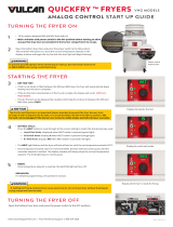
FINDING YOUR WAY AROUND THE BIPH55 SERIES GAS FRYER
TYPICAL CONFIGURATION (BIPH255 SHOWN)
NOTE: The appearance of your fryer may differ slightly from that
shown depending upon configuration and date of manufacture.
Flue
Top Cap
Gas Valve
Control Panel (M2000
Computer Shown)
Gas Valve
Filter Control Handles
Drain Handles
FootPrint Pro Built-in
Filtration Unit
Combustion
Blower
Combustion
Blower
Flue Cap
Basket Hangers
/