Page is loading ...

Manual 2100-518B
Page 1 of 30
WARNING: After ushing is complete, but prior to pump motor start-up, loosen the large screw in
the center of the pump motor(s) to allow air to escape. Once water has seeped out around the screw,
re-tighten. Failure to perform this step will likely result in premature pump motor failure!
PUMP MOTOR REPLACEMENT: Bard Part #8300-003 (UP26-99F)
Manual: 2100-518B
Supersedes: 2100-518A
File: Volume I, Tab 8
Date: 04-23-12
INSTALLATION
INSTRUCTIONS
DOUBLE O-RING
GEOTHERMAL
FLOW CENTERS
Models:
DORFC-1 DORFC-2
BMC, Inc.
Bryan, Ohio 43506
DORFC-1 DORFC-2

Manual 2100-518B
Page 2 of 30
CONTENTS
Getting Other Informations and Publications .........3
General Information
Flow Center Nomenclature .......................................4
Application
Description ................................................................ 4
Safety .................................................................4
Danger .................................................................4
Warning .................................................................4
Caution .................................................................4
Notice .................................................................4
Flow Center Mounting Instructions
Notice .................................................................7
Stud Wall .................................................................7
Concrete/Masonry Wall .............................................7
Side of Unit ...............................................................7
Piping Installation
Description .............................................................. 10
Actual Photo Images ..........................................10-11
Multiple Unit to Single Loop Connection
Description .............................................................. 12
Flow Center Wiring
Description .............................................................. 16
Flushing & Charging
General ...............................................................18
Procedures for Adding Antifreeze ...........................18
Flushing & Filling Earth Loop & Units .....................22
Flushing Earth Loop Only .......................................22
Flushing Unit Only ...................................................23
Flow Center Initial Startup
General ...............................................................24
Procedures for Pressurizing the System .................24
Pressure/Temperature Plugs ..................................24
Troubleshooting
Troubleshooting Table .............................................27
Antifreeze Selection & Use
General ...............................................................28
Methanol ...............................................................28
Ethanol ...............................................................28
Propylene Glycol .....................................................29
Potassium Acetate (GS4) ........................................29
Antifreeze Verication ............................................. 30
Figures
Figure 1A Performance Model DORFC-1 .................5
Figure 1B Performance Model DORFC-2 .................5
Figure 2 Flow Center Dimensions .......................... 6
Figure 3 Pump Horizontal Applications ..................8
Figure 4A Mounting - Studded Wall .......................... 9
Figure 4B Mounting - Masonry Wall ..........................9
Figure 5A Flow Center Connection to GV Series ...12
Figure 5B Flow Center Connection to GT Series ...13
Figure 5C Flow Center Connection to QW Series ..14
Figure 6 Multiple Unit Connection to Singular ...... 15
Figure 7 Electrical Connections ............................17
Figure 8 Connecting Flush Cart to Flow Center ... 19
Figure 9A Positioning - Flush Loop .........................20
Figure 9B Positioning - Flush Loop & Unit ..............20
Figure 9C Positioning - Flush Unit ..........................21
Figure 9D Positioning - Operation ...........................21
Figure 10 Pressure Temperature Ports ..................25
Figure 11 Density Verication - Solution Strength ....30
Tables
Table 1 Fusion or Barbed Fittings ....................... 10
Table 2 Electrical Ratings ...................................16
Table 3A GV Series Coil Pressure Drop ...............25
Table 3B GT Series Coil Pressure Drop ................26
Table 3C QW Series Coil Pressure Drop ..............26
Table Troubleshooting......................................27
Table 4 Fluid Volume ..........................................29
Table 5 Percentages by Volume .........................29
Table 6 Propylene Glycol Specic Gravity .......... 30
Table 7 Methanol Specic Gravity ......................30

Manual 2100-518B
Page 3 of 30
GETTING OTHER INFORMATION AND PUBLICATIONS
These publications can help you install the air
conditioner or heat pump. You can usually nd these
at your local library or purchase them directly from the
publisher. Be sure to consult current edition of each
standard.
National Electrical Code .......................ANSI/NFPA 70
Standard for the Installation ...............ANSI/NFPA 90A
of Air Conditioning and Ventilating Systems
Standard for Warm Air ....................... ANSI/NFPA 90B
Heating and Air Conditioning Systems
Load Calculation for Residential ......ACCA Manual J
Winter and Summer Air Conditioning
Duct Design for Residential .............. ACCA Manual D
Winter and Summer Air Conditioning and Equipment
Selection
Closed-Loop/Ground Source Heat Pump ........IGSHPA
Systems Installation Guide
Grouting Procedures for Ground-Source .........IGSHPA
Heat Pump Systems
Soil and Rock Classication for ......................IGSHPA
the Design of Ground-Coupled Heat Pump Systems
Ground Source Installation Standards .............IGSHPA
Closed-Loop Geothermal Systems ..................IGSHPA
– Slinky Installation Guide
FOR MORE INFORMATION, CONTACT
THESE PUBLISHERS:
ACCA Air Conditioning Contractors of America
1712 New Hampshire Avenue
Washington, DC 20009
Telephone: (202) 483-9370
Fax: (202) 234-4721
ANSI American National Standards Institute
11 West Street, 13th Floor
New York, NY 10036
Telephone: (212) 642-4900
Fax: (212) 302-1286
ASHRAE American Society of Heating Refrigerating,
and Air Conditioning Engineers, Inc.
1791 Tullie Circle, N.E.
Atlanta, GA 30329-2305
Telephone: (404) 636-8400
Fax: (404) 321-5478
NFPA National Fire Protection Association
Batterymarch Park
P.O. Box 9101
Quincy, MA 02269-9901
Telephone: (800) 344-3555
Fax: (617) 984-7057
IGSHPA International Ground Source
Heat Pump Association
490 Cordell South
Stillwater, OK 74078-8018

Manual 2100-518B
Page 4 of 30
GEOTHERMAL FLOW CENTERS NOMENCLATURE
FLOW CENTER DESCRIPTION
The DORFC Series Flow Centers are a compact, easy to
mount polystyrene cabinet that contains 3-way valves and
pump(s) with connections for ushing, lling and pumping
uids for geothermal closed loop systems. The proven
design is foam insulated to prevent condensation and full
ow service valves minimize pressure drop.
One or two Grundfos pump models UP26-99 are available
based upon ow requirements and loop design.
Unit and loop connections are designed for double o-ring
ttings with several varieties of connections available
(fusion, threaded, barbed and sweat). Pump motor(s) are
230VAC, 60 Hz, 1-phase.
An attractive light gray polystyrene cabinet (that matches
geothermal unit) with black pump(s) provides an
aesthetically pleasing enclosure for pump(s) and valves.
SAFETY
Warnings, cautions and notices appear throughout this
Manual. Read these items carefully before attempting any
installation, service or troubleshooting of the equipment.
DANGER
Indicates an immediate hazardous situation which, if not
avoided, will result in death or serious injury. DANGER
labels on unit access panels must be observed.
WARNING
Indicates a potentially hazardous situation which, if not
avoided, will result in death or serious injury.
CAUTION
Indicates a potentially hazardous situation or an unsafe
practice which, if not avoided, could result in minor or
moderate injury or product or property damage.
NOTICE
Notication of installation, operation or maintenance
information, which is important, but which is not hazard-
related.
DORFC 2
1 = 1-Pump Version, 208/230V, 60 Hz, 1-phase, 22’ HD @ 16 GPM
2 = 2-Pump Version, 208/230V, 60 Hz, 1-phase, 44’ HD @ 16 GPM
Double
O-Ring
Flow
Center
WARNING
Failure to do so could cause property
damage, bodily harm or death.
CAUTION
Failure to do so could cause property
damage, bodily harm or death.

Manual 2100-518B
Page 5 of 30
Manual 2100-518A
Page 5 of 30
0
10
20
30
40
50
60
70
0 5 10 15 20 25 30 35
Flow (GPM)
Head (Feet)
FIGURE 1B
PERFORMANCE MODEL DORFC-2 FLOW CENTER
0
5
10
15
20
25
30
35
0 5 10 15 20 25 30 35
Flow (GPM)
Head (Feet)
FIGURE 1A
PERFORMANCE MODEL DORFC-1 FLOW CENTER
FLOW CENTER PERFORMANCE
FLOW CENTER PERFORMANCE

Manual 2100-518B
Page 6 of 30
GF
B
D
H
MIS-2658
11.431.5 5.1 6.7 12.719.1
A B C D E F G H
INCHES 13.5 10.3 7.5 12.4 2.0 2.6 5.0 4.7
CM 34.3 26.2
TYPE SHIPPING WEIGHT
DORFC-1 26 LBS
DORFC-2 31 LBS
C
A
DIMENSIONAL DRAWING
FIGURE 2
FLOW CENTER DIMENSIONS

Manual 2100-518B
Page 7 of 30
NOTICE
The Flow Center must be mounted with the pump shaft in
the horizontal position. In other words, it should always be
mounted in a vertical position (not on its back or mounted to
the ceiling). See Figure 3.
The pump should be located as close to the unit as possible
to limit the length of rubber hose kit or interconnect piping
and thus its associated pressure drop.
STUD WALL
Mounting on stud wall with or without drywall can be
accomplished by using two (2) lag bolts through the top and
bottom center holes directly into the stud. See Figure 4A.
CONCRETE/MASONRY WALL
Mounting onto a concrete wall can be accomplished
typically using four (4) 1/4" diameter tapcon cement screws
in the four (4) outer corner mounting holes. See Figure 4B.
SIDE OF UNIT
Mounting on the side of the unit is possible, but
not necessarily recommended because it can inhibit
serviceability and also lead to vibration of the sheet
metal casing. It could also lead to puncturing an internal
refrigerant or water pipe. If necessary, however, the ow
center can be mounted to the sheet metal casing utilizing
four (4) self-drilling screws. (Pay close attention not to
puncture internal components.)
FLOW CENTER MOUNTING
CAUTION
The following instructions represent
industry accepted installation practices for
closed-loop earth coupled (ground loop)
installations. Instructions are provided to
assist the contractor in installing trouble
free ground loops. These instructions are
recommendations only. State/provincial and
local codes MUST be followed and installation
MUST conform to ALL applicable codes. It is
the responsibility of the installing contractor
to determine and comply with ALL applicable
codes and regulations.

Manual 2100-518B
Page 8 of 30
OK
HORIZONTAL
OK
IMPELLER SHAFT
HORIZONTAL
IMPELLER SHAFT
MIS-2659
NO
IMPELLER SHAFT
CAN NOT BE
VERTICAL
FIGURE 3
PUMP HORIZONTAL APPLICATIONS

Manual 2100-518B
Page 9 of 30
1/4" TAPCON SCREWS
MIS-2660
1/4" LAG BOLTS
DIRECTLY INTO STUD
FIGURE 4
MOUNTING
FIGURE 4A
Studded Wall Mounting
FIGURE 4B
Masonry Wall Mounting

Manual 2100-518B
Page 10 of 30
The Flow Center features Double O-Ring ttings for
installation exibility and ease of installation – maintaining
a reliable connection. Table 1 illustrates the connection
options available for Flow Centers. Pressure drop in
piping systems should be calculated to ensure adequate
ow through the unit. All piping should be properly
insulated with closed cell insulation of 1/2" wall thickness.
Piping insulation should be glued and sealed to prevent
condensation using closed cell insulation glue. The swivel
connectors on the ow center and at the unit are designed
to be hand-tightened only.
NOTE: Apply petroleum jelly to O-Rings to prevent
damage and aid in insertion.
Loop side piping is typically polyethylene piping directly into
the ow center. Connection to the ow center can be made
with either a fusion or barbed tting as shown in Table 1.
Connection between the ow center and the geothermal
heat pump typically would be made using the hose kit
(DORLFCK-1), which contains all ttings necessary for
connection between the heat pump and the ow center as
shown in Figure 5. Other variety of materials may also be
used for this connection - such as PE or copper piping.
1-1/4" Socket Fusion X
Double O-ring
DORF125-S
1" Hose Barb X
Double O-ring
DORB1-S-4HC
1" MPT X Double O-ring
DORMP1-S
Description Part Number
1-1/4" PE Fusion X Double O-Ring DORF125-S
Double O-Ring Loop Flow Center Kit DORLFCK-1
1" Barb X Double O-Ring (includes {4} hose clamps) DORB1-S-4HC
1" MPT X Double O-Ring DORMP1-S
1" FPT X Double O-Ring DORFP1-S
1" Copper Sweat X Double O-Ring (includes {2} P/T ttings) DORS1-S
1" Hose Barb X Double O-Ring 90° Elbow (includes {4} hose clamps and {2} P/T ttings) DORB1-90-4HC
1" MPT X Double O-Ring, 90° Elbow (includes {2} P/T ttings) DORMP1-90
Quick Connect Cam Lock X Double O-Ring 90° Elbow DORCL1-90
Male Garden Hose Thread X Double O-Ring (1-piece per box) DORGHMT
PIPING INSTALLATION
TABLE 1
NOTE: All
ttings boxed in pairs (2-pieces each) will exception of DORGHMT.

Manual 2100-518B
Page 11 of 30
1" Swivel X Double O-ring
DORFP1-S
1" Copper Sweat X Double O-ring with 1/4"
FPT Port & Pressure/Temperature Test Plugs
DORS1-S
Elbow, 1" Hose Barb X Double
O-ring with 1/4" Port and Pressure/
Temperature Test Plugs
DORB1-90-4HC
Elbow, 1" MPT X Double
O-ring with 1/4" Port and
Pressure/Temperature Test Plugs
DORMP1-90
1" Cam Lever Male X
Double O-ring
DORCL1-90
Garden Hose Male X O-ring
(single) Adapter
DORGHMT
PIPING INSTALLATION (CONTINUED)
NOTES:
1. Apply petroleum jelly to O-Rings to prevent damage and aid in insertion.
2. Use two (2) stainless steel clamps per connection (included quantities of hose clamps with ttings and hose kits are
per this recommendation).
3. Adaptors required from 1" MPT, 1" FPT, Copper, etc. provided by others.

Manual 2100-518B
Page 12 of 30
MULTIPLE UNIT TO SINGLE LOOP
CONNECTION
In instances where multiple units are connected to a singular
loop, our recommendation is to apply a ow center to each
individual system with full-port balancing valves installed
on each unit. See Figure 6.
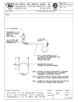
FIGURE 5A
FLOW CENTER CONNECTION TO GV SERIES MODEL
MIS-2621 A
PUMP
WALL BRACKET
FIELD-FABRICATED
WATER IN
HOSE CLAMPS
PIPE TO GROUND LOOP
PIPE FROM
STRAIGHT BARBED
BRASS ADAPTERS
MODULE
WATER OUT
1" FLEXIBLE HOSE
GROUND LOOP
OPTIONAL VISUAL
FLOW METER
NOTE: IF USED
SUPPORT WITH A
NOTE: APPLY PETROLEUM JELLY
TO O-RINGS TO PREVENT DAMAGE
AND AID IN INSERTION.

Manual 2100-518B
Page 13 of 30
FIGURE 5B
FLOW CENTER CONNECTION TO GT SERIES MODEL
NOTE: APPLY PETROLEUM JELLY
TO O-RINGS TO PREVENT DAMAGE
AND AID IN INSERTION
WATER IN
WATER OUT
GOUND LOOP
PIPE FROM
GROUND LOOP
PIPE TO
BRASS ADAPTERS
NOTE: IF USED SUPPORT
WALL BRACKET
WITH A FIELD FABRICATED
1" FLEXIBLE HOSE
HOSE CLAMPS
FLOW METER
OPTIONAL VISUAL
STRAIGHT BARBED
PUMP MODULE
MIS-2827 A

Manual 2100-518B
Page 14 of 30
FIGURE 5C
FLOW CENTER CONNECTION TO QW SERIES MODEL
NOTE: Apply petroleum
jelly to o-rings to prevent
damage and aid in insertion
MIS-2748 A
FLEXIBLE HOSE
for Model No.)
(See Spec Sheet
GROUND LOOP
PIPE FROM
PUMP MODULE
PIPE TO
GROUND
LOOP
WATER
OUT

Manual 2100-518B
Page 15 of 30
GROUND
FULL PORT BALL
VALVE FOR BALANCING
LOOP
4. All units must include P/T ports for flow rate measure and balancing.
FIELD SUPPLIED
MIS-2664
NOTES:
1. Piping is shown schematically. Actual pipe diameter and layout must be determined before installation.
2. Pressure drop calculation must be made to verify that parallel pumping arrangement provides enough head to deliver design flow rate to each unit
when all units are operating.
3. Flow controller should be mounted close enough to unit to maintain short (aprox. 10 ft., 3m) hose kit from Flow Controller to unit.
FIELD SUPPLIED
CHECK VALVE TO
PREVENT SHORT CYCLING
EACH HEAT PUMP
MUST INCLUDE P/T
PORTS TO VERIFY
FLOW RATES
FIGURE 6
MULTIPLE UNIT CONNECTION TO SINGULAR GROUND LOOP

Manual 2100-518B
Page 16 of 30
Power wiring to the Flow Center should conform to all applicable codes. Figure 7 shows the required wiring between the
geothermal heat pump and the ow center. NOTE: the ow center is only available in 208/230 Volt, 60 Hz, 1-phase. The ow
center electrical connection interior of the heat pump control panel is circuit breaker protected (both L1 and L2 power lines).
See Table 2 for the electrical requirements.
MODEL
PUMP
QUANTITY
VOLTS AMPS HP
DORFC-1 1 230 1.07 1/6
DORFC-2 2 230 2.14 1/3
FLOW CENTER WIRING
WARNING
To avoid possible injury or death due to
electrical shock, open the power supply
disconnect switch and secure it in an open
position during installation.
CAUTION
Use only copper conductors for eld installed
electrical wiring. Unit terminals are not
designed to accept other types of conductors.
TABLE 2
ELECTRICAL RATINGS

Manual 2100-518B
Page 17 of 30
L2
L1
3
PUSH
3
PUSH
Terminal Block
FLOW CENTER
CONNECTION
FLOW CENTER
ELECTRICAL
ENTRANCE
MIS-2665
38
Circuit Breakers
Red
37
Black
2
FIGURE 7
ELECTRICAL CONNECTIONS

Manual 2100-518B
Page 18 of 30
All Flushing of earth loops should be performed using a
1.5 HP or larger pump (as specied by IGSHPA). Flushing
can be accomplished using three different methods. The
rst ushing method applies a one-step installation of the
loop, unit and inside piping. The second method allows a
Loop Contractor to use ush cart when installing the loop,
and at a later date, the dealer can install the unit to the
loop using only domestic water to ush the unit. The third
procedure shown is used when replacing the pump, coaxial
refrigerant to water coil, or unit. The following are step-by-
step procedures. Be careful not to rotate the 3-way valves
into a position where air can be introduced into the loop.
Reushing will be required if this occurs. Valve position
can be veried by looking on the end of the valve stem for
the pattern position.
Consult the IGSHPA for more complete ushing and
antifreeze instructions.
Flush in one direction for one hour, deadheading
in increments - checking site glass for air pockets.
Reverse ow in opposite direction, again for one hour,
deadheading in increments - checking site glass for air
pockets.
The presence of air can be detected by “deadheading” the
pump. To deadhead the pump, close off the return to the
pump and watch the water level site glass. Once you have
no more than 1/2" to 3/4" drop in the site glass, you will
have achieved complete air removal.
Power ushing can be achieved using the home’s city water
supply (or well water) connected to the ush cart. This
uses the combined pressure of the ush cart pump and the
home’s water system for faster ushing.
After ushing is complete, but prior to unit start up,
remove the large screw from the center of the ow center
pump(s) to allow air to escape (water will drip out).
Replace the screw after pump has lled with uid.
For nal pressurization, run the unit in heating or cooling
for a period of 20 minutes. Following this 20 minute run
time, pressurize the loop using the ush cart to 50-75 psig in
winter or 40-50 psig in summer.
In areas where entering loop temperatures drop below
40°F (5°C) or where piping will be routed through areas
subject to freezing, antifreeze is needed to prevent the loop
from freezing inside the pipe or heat exchanger. Alcohols
and glycols are commonly used as antifreeze, however,
you should consult with your distributor for assistance in
selecting the antifreeze best suited for your region.
PROCEDURES FOR ADDING
ANTIFREEZE
1. Flush cart should be half full of water.
2. Add measured amount of antifreeze through hose
below the water level (calculate based upon loop).
3. Add antifreeze to loop side only (see valve position in
Figure 9A).
4. Pump and dump (discharge).
5. Turn off pump; close discharge valve.
6. Repeat the procedure to add remaining antifreeze to
loop.
FLUSHING & CHARGING

Manual 2100-518B
Page 19 of 30
SUPPLY
RETURN
MIS-2661
FLUSHING & CHARGING (CONTINUED)
FIGURE 8
CONNECTING FLUSH CART TO FLOW CENTER

Manual 2100-518B
Page 20 of 30
MIS-2662
FLUSH LOOP ONLY
FLUSH LOOP & UNIT TOGETHER
FLUSHING & CHARGING (CONTINUED)
FIGURES 9A & 9B
FLOW CENTER VALVE POSITIONING
/