Generac 004090-2, 004091-2, 004092-2, 004093-2, 004094-2, 004095-2, 004096-2, 004097-2, 004474-0 User manual
- Category
- Power generators
- Type
- User manual

POWER SYSTEMS, INC.
®
Owner’s Manual
Liquid-cooled, Prepackaged
Standby Generators
Model Numbers
(Natural Gas)
004090-2 004091-2
004092-2 004093-2
004094-2 004095-2
004096-2 004097-2
004474-0 (w/TS)
(Liquid Propane Vapor)
004124-1 004125-1
004126-1 004127-1
004128-1 004130-1
004131-1
004475-0 (w/TS)
ONLY QUALIFIED ELECTRICIANS OR CONTRACTORS
SHOULD ATTEMPT INSTALLATION!!

Generac
®
Power Systems, Inc.
INTRODUCTION
Thank you for purchasing this model of the standby gen-
erator set product line by Generac Power Systems.
Every effort was expended to make sure that the infor-
mation and instructions in this manual were both accu-
rate and current at the time the manual was written.
However, the manufacturer reserves the right to change,
alter or otherwise improve this product(s) at any time
without prior notice.
READ THIS MANUAL THOROUGHLY
If you do not understand any portion of this manual,
contact Generac or your nearest Generac Authorized
Service Dealer for starting, operating and servicing pro-
cedures.
Throughout this publication, and on tags and
decals affixed to the generator, DANGER, WARNING,
CAUTION and NOTE blocks are used to alert you to spe-
cial instruction about a particular service or operation
that may be hazardous if performed incorrectly or care-
lessly. Observe them carefully. Their definitions are as fol-
lows:
After this heading, you can read instructions that, if
not strictly complied with, will result in personal injury
or property damage.
After this heading, you can read instructions that, if not
strictly complied with, may result in personal injury or
property damage.
After this heading, you can read instructions that, if not
strictly complied with, could result in damage to equip-
ment and/or property.
NOTE:
After this heading, you can read explanatory state-
ments that require special emphasis.
These safety warnings cannot eliminate the hazards that
they indicate. Common sense and strict compliance with
the special instructions while performing the service are
essential to preventing accidents.
Four commonly used safety symbols accompany the
DANGER, WARNING and CAUTION blocks. The type of
information each indicates is as follows:
This symbol points out important safety information
that, if not followed, could endanger personal safety
and/or property of you and others.
This symbol points out potential explosion hazard.
This symbol points out potential fire hazard.
This symbol points out potential electrical shock
hazard.
The operator is responsible for proper and safe use of
the equipment. We strongly recommend that the opera-
tor read this Owner's Manual and thoroughly under-
stand all instructions before using this equipment. We
also strongly recommend instructing other users to
properly start and operate the unit. This prepares them
if they need to operate the equipment in an emergency.
OPERATION AND MAINTENANCE
It is the operator's responsibility to perform all safety
checks, to make sure that all maintenance for safe oper-
ation is performed promptly, and to have the equipment
checked periodically by a Generac Authorized Service
Dealer. Normal maintenance service and replacement of
parts are the responsibility of the owner/operator and,
as such, are not considered defects in materials or work-
manship within the terms of the warranty. Individual
operating habits and usage contribute to the need for
maintenance service.
Proper maintenance and care of your generator ensure a
minimum number of problems and keep operating
expenses at a minimum. See your Generac Authorized
Service Dealer for service aids and accessories.
Operating instructions presented in this manual
assume that the standby electric system has been
installed by a Generac Authorized Service Dealer or
other competent, qualified contractor. Installation of
this equipment is not a “do-it-yourself” project.
HOW TO OBTAIN SERVICE
When your generator requires servicing or repairs, sim-
ply contact a Generac Authorized Service Dealer for
assistance. Service technicians are factory-trained and
are capable of handling all of your service needs.
When contacting a Generac Authorized Service Dealer
or the factory about parts and service, always supply the
complete model number of your unit as given on the
front cover of this manual or on the DATA CARD affixed
to the unit.
AUTHORIZED SERVICE
DEALER LOCATION
To locate the GENERAC AUTHORIZED SERVICE
DEALER nearest you, please call this number:
1-800-333-1322
OR
Locate us on the web at:
www.generac.com

Table of Contents
Guardian Liquid-cooled 10 kW, 15 kW, 20 kW and 25 kW Generators
Generac
®
Power Systems, Inc. 1
INTRODUCTION ............................................................IFC
SAFETY RULES ........................................................................2
Section 1
GENERAL INFORMATION ........................................................4
Generator ....................................................................................4
Automatic System Operation ......................................................4
Generator AC Connection Systems ............................................4
Main Circuit Breaker....................................................................5
Generator Fuel System ..............................................................5
Engine Protective Devices ..........................................................5
Generator Specifications ............................................................6
Unpacking....................................................................................7
Lifting the Generator ..................................................................7
Engine Specifications ..................................................................7
Fuel Consumption ......................................................................7
Lifting the Generator ..................................................................7
Torque Specifications ..................................................................8
Engine Oil Recommendations ....................................................8
Coolant Recommendations ........................................................8
Before Installation........................................................................8
Section 2
STANDBY GENERATOR INSTALLATION ................................9
Basic Standby Electric System..............................................................9
Emergency Circuit Isolation Method....................................................10
Total Circuit Isolation Method ..............................................................10
Grounding the Generator ....................................................................10
Generator AC Neutral Connections ....................................................10
Transfer Switch Start Signal Connections ..........................................10
Battery Installation ..............................................................................10
Preparation Before Start-Up................................................................11
Section 3
OPERATION ............................................................................12
Using a Standard “GTS” Transfer Switch ..................................12
Control Console Components ..................................................13
Manual Transfer and Startup ....................................................13
Retransfer and Shutdown..........................................................14
Automatic Operation..................................................................14
Weekly Exercise Cycle..............................................................14
Engine Heater ..........................................................................14
Section 4
MAINTENANCE........................................................................15
Maintenance Performed by
Authorized Service Facilities ....................................................15
Overload Protection for Engine DC Electrical System ..............15
Checking Fluid Levels ..............................................................15
Maintenance Owner/Operator Can Perform..............................16
Miscellaneous Maintenance ......................................................17
Section 5
TROUBLESHOOTING ..............................................................18
Section 6
SCHEDULED MAINTENANCE ................................................19
Section 7
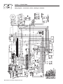
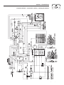
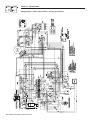
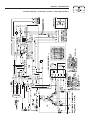
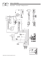
WIRING DIAGRAMS AND SCHEMATICS ..........................22-27
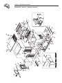
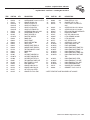
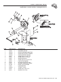
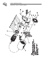
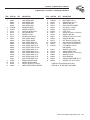
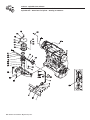
Section 8
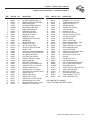
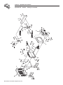
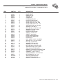
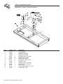
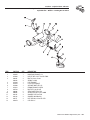
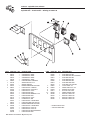
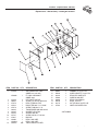
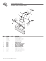
EXPLODED VIEWS AND PARTS LISTS ............................28-45
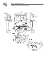
Section 9
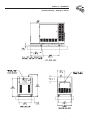
INSTALLATION DRAWINGS ..............................................46-47
Section 10
WARRANTY .......................................................48- Back Cover
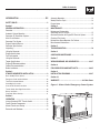
Figure 1- Water Cooled Emergency Power System

2 Generac
®
Power Systems, Inc.
Study these SAFETY RULES carefully before installing,
operating or servicing this equipment. Become familiar
with this Owner’s Manual and with the unit. The genera-
tor can operate safely, efficiently and reliably only if it is
properly installed, operated and maintained. Many acci-
dents are caused by failing to follow simple and funda-
mental rules or precautions.
Generac cannot possibly anticipate every possible cir-
cumstance that might involve a hazard. The warnings in
this manual, and on tags and decals
affixed to the unit are, therefore, not all-inclusive. If you
use a procedure, work method or operating technique
that Generac does not specifically recommend, you
must satisfy yourself that it is safe for you and others.
You also must make sure the procedure, work method
or operating technique that you choose does not render
the generator unsafe.
Despite the safe design of this generator,
operating this equipment imprudently, neglecting its
maintenance or being careless can cause
possible injury or death. Permit only responsible and
capable persons to install, operate or maintain this
equipment.
Potentially lethal voltages are generated by these
machines. Ensure all steps are taken to render the
machine safe before attempting to work on the
generator.
Parts of the generator are rotating and/or hot
during operation. Exercise care near running gen-
erators.
GENER
AL HAZARDS
• For safety reasons, Generac recommends
that this equipment be installed, serviced and
repaired by a Generac Authorized Service Dealer or
other competent, qualified electrician or installation
technician who is familiar with applicable codes,
standards and regulations. The operator also must
comply with all such codes, standards and regula-
tions.
• Installation, operation, servicing and repair of this
(and related) equipment must always comply with
applicable codes, standards, laws and regulations.
Adhere strictly to local, state and national electrical
and building codes. Comply with regulations the
Occupational Safety and Health Administration
(OSHA) has established. Also, ensure that the gener-
ator is installed, operated and serviced in accordance
with the manufacturer’s instructions and recommen-
dations. Following installation, you must not do any-
thing that might render the unit unsafe or in non-
compliance with the aforementioned codes, stan-
dards, laws and regulations.
• The engine exhaust fumes contain carbon monoxide
gas, which can be DEADLY. This dangerous gas, if
breathed in sufficient concentrations, can cause
unconsciousness or even death. For that reason, ade-
quate ventilation must be provided. Exhaust gases
must be piped safely away from any building or
enclosure that houses the generator to an area where
people, animals, etc., will not be harmed. This
exhaust system must be installed properly, in strict
compliance with applicable codes and standards.
• Keep hands, feet, clothing, etc., away from drive belts,
fans, and other moving or hot parts. Never remove
any drive belt or fan guard while the unit is operating.
• Adequate, unobstructed flow of cooling and ventilat-
ing air is critical in any room or building housing the
generator to prevent buildup of explosive gases and
to ensure correct generator operation. Do not alter
the installation or permit even partial blockage of
ventilation provisions, as this can seriously affect safe
operation of the generator.
• Keep the area around the generator clean and unclut-
tered. Remove any materials that could become haz-
ardous.
• When working on this equipment, remain alert at all
times. Never work on the equipment when you are
physically or mentally fatigued.
Important Safety Instructions
Guardian Liquid-cooled 10 kW, 15 kW, 20 kW and 25 kW Generators
SAVE THESE INSTRUCTIONS – The manufacturer suggests that these rules for safe
operation be copied and posted in potential hazard areas. Safety should be stressed to all
operators, potential operators, and service and repair technicians for this equipment.
SAVE THESE INSTRUCTIONS – This manual contains important instructions that should be
followed during installation and maintenance of the generator and batteries.
The engine exhaust from this product
contains chemicals known to the state
of California to cause cancer, birth
defects or other reproductive harm.
WARNING:
This product contains or emits chemicals
known to the state of California to cause
cancer, birth defects or other reproductive harm.
WARNING:

Generac
®
Power Systems, Inc. 3
• Inspect the generator regularly, and promptly repair
or replace all worn, damaged or defective parts using
only factory-approved parts.
• Before performing any maintenance on the generator,
disconnect its battery cables to prevent accidental
start-up. Disconnect the cable from the battery post
indicated by a NEGATIVE, NEG or (–) first.
Reconnect that cable last.
• Never use the generator or any of its parts as a step.
Stepping on the unit can stress and break parts, and
may result in dangerous operating conditions from
leaking exhaust gases, fuel leakage, oil leakage, etc.
ELE
CTRICAL HAZARDS
• All generators covered by this manual produce dan-
gerous electrical voltages and can cause fatal electrical
shock. Utility power delivers extremely high and dan-
gerous voltages to the transfer switch as well as the
standby generator. Avoid contact with bare wires, ter-
minals, connections, etc., on the generator as well as
the transfer switch, if applicable. Ensure all appropri-
ate covers, guards and barriers are in place before
operating the generator. If you must work around an
operating unit, stand on an insulated, dry surface to
reduce shock hazard.
• Do not handle any kind of electrical device while
standing in water, while barefoot, or while hands or
feet are wet. DANGEROUS ELECTRICAL SHOCK
MAY RESULT.
• If people must stand on metal or concrete while
installing, operating, servicing, adjusting or repairing
this equipment, place insulative mats over a dry
wooden platform. Work on the equipment only while
standing on such insulative mats.
• The National Electrical Code (NEC), Article 250
requires the frame and external electrically conduc-
tive parts of the generator to be connected to an
approved earth ground and/or grounding rods. This
grounding will help prevent dangerous electrical
shock that might be caused by a ground fault condi-
tion in the generator set or by static electricity. Never
disconnect the ground wire.
• Wire gauge sizes of electrical wiring, cables and cord
sets must be adequate to handle the maximum elec-
trical current (ampacity) to which they will be sub-
jected.
• Before installing or servicing this (and related) equip-
ment, make sure that all power voltage supplies are
positively turned off at their source. Failure to do so
will result in hazardous and possibly fatal electrical
shock.
• Connecting this unit to an electrical system normally
supplied by an electric utility shall be by means of a
transfer switch so as to isolate the generator electric
system from the electric utility distribution system
when the generator is operating. Failure to isolate the
two electric system power sources from each other by
such means will result in damage to the generator
and may also result in injury or death to utility power
workers due to backfeed of electrical energy.
• Generators installed with an automatic transfer
switch will crank and start automatically when nor-
mal (utility) source voltage is removed or is below an
acceptable preset level. To prevent such automatic
start-up and possible injury to personnel, disable the
generator’s automatic start circuit (battery cables,
etc.) before working on or around the unit. Then,
place a “Do Not Operate” tag on the generator control
panel and on the transfer switch.
• In case of accident caused by electric shock, immedi-
ately shut down the source of electrical power. If this
is not possible, attempt to free the victim from the
live conductor. AVOID DIRECT CONTACT WITH
THE VICTIM. Use a nonconducting implement, such
as a dry rope or board, to free the victim from the live
conductor. If the victim is unconscious, apply first aid
and get immediate medical help.
• Never wear jewelry when working on this equipment.
Jewelry can conduct electricity resulting in electric
shock, or may get caught in moving components
causing injury.
F
IREHAZARDS
• Keep a fire extinguisher near the generator at all
times. Do NOT use any carbon tetra-chloride type
extinguisher. Its fumes are toxic, and the liquid can
deteriorate wiring insulation. Keep the extinguisher
properly charged and be familiar with its use. If you
have any question pertaining to fire extinguishers,
consult your local fire department.
EXPLOSION HAZARDS
• Properly ventilate any room or building housing the
generator to prevent build-up of explosive gas.
• Do not smoke around the generator. Wipe up any fuel
or oil spills immediately. Ensure that no combustible
materials are left in the generator compartment, or
on or near the generator, as FIRE or EXPLOSION
may result. Keep the area surrounding the generator
clean and free from debris.
• Generac generator sets may operate using one of sev-
eral types of fuels. All fuel types are potentially FLAM-
MABLE and/or EXPLOSIVE and should be handled
with care. Comply with all laws regulating the storage
and handling of fuels. Inspect the unit’s fuel system
frequently and correct any leaks immediately. Fuel
supply lines must be properly installed, purged and
leak tested according to applicable fuel-gas codes
before placing this equipment into service.
• Diesel fuels are highly FLAMMABLE. Gaseous fluids
such as natural gas and liquid propane (LP) gas are
extremely EXPLOSIVE. Natural gas is lighter than air,
and LP gas is heavier than air; install leak detectors
accordingly.
Important Safety Instructions
Guardian Liquid-cooled 10 kW, 15 kW, 20 kW and 25 kW Generators

4 Generac
®
Power Systems, Inc.
GENERATOR
This equipment is an water-cooled, engine-driven gen-
erator set. The generator is designed to supply electrical
power that operates critical electrical loads during util-
ity power failure. The unit has been factory-installed in
a weather resistant, all metal sound attenuated enclo-
sure and is intended for outdoor installation only. Use
this generator as a source of electrical power for the
operation of 120 and/or 240 volts, single or 3-phase
loads, or 120 and/or 208 volts, 3-phase loads.
These models are available. They are rated as follows:
Model 004090: Provides 10,000 watts (10 kW) of 1-phase power.
Model 004091: Provides 10,000 watts (10 kW) of 3-phase power.
Model 004124: Provides 10,000 watts (10 kW) of 1-phase power.
Model 004125: Provides 10,000 watts (10 kW) of 3-phase power.
Model 004092: Provides 15,000 watts (15 kW) of 1 phase power.
Model 004093: Provides 15,000 watts (15 kW) of 3 phase power.
Model 004126: Provides 15,000 watts (15 kW) of 1 phase power.
Model 004127: Provides 15,000 watts (15 kW) of 3 phase power.
Model 004094: Provides 20,000 watts (20 kW) of 1-phase power.
Model 004095: Provides 20,000 watts (20 kW) of 3-phase power.
Model 004128: Provides 20,000 watts (20 kW) of 1-phase power.
Model 004096: Provides 25,000 watts (25 kW) of 1 phase power.
Model 004097: Provides 25,000 watts (25 kW) of 3 phase power.
Model 004130: Provides 25,000 watts (25 kW) of 1 phase power.
Model 004131: Provides 25,000 watts (25 kW) of 3 phase power.
Model 004474: Provides 25,000 watts (25 kW) of 1 phase power.
Model 004475: Provides 25,000 watts (25 kW) of 1 phase power.
WARNING: If this generator is used to power
electrical load circuits normally powered by a
utility power source, you are required by code to
install a transfer switch. The transfer switch must
effectively isolate the electric system from the
utility distribution system when the generator is
operating (NEC 701). Failure to isolate an electri-
cal system by such means results in damage to
the generator and may also result in injury or
even death to utility power workers due to back-
feed of electrical energy.
AUTOMATIC SYSTEM OPERATION
When this generator along with its transfer switch has
been installed and interconnected, a circuit board in the
generator panel constantly monitors utility power
source voltage. Should that voltage drop below a preset
value, and remain at such a low state for a preset
amount of time, the generator cranks and starts. After
the generator starts, the transfer switch transfers load
circuits so the generator can power them.
When utility source voltage has been restored, the
switch re-transfers back to the utility source voltage and
the generator then shuts down.
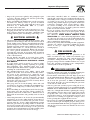
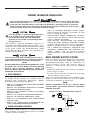
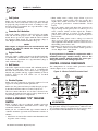
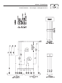
GENERATOR AC
CONNECTION SYSTEMS
The generator was shipped from the factory with its sta-
tor AC output leads connected in one of the “Delta” con-
figurations, as shown in Figure 2. This type of connec-
tion system will supply a 120 and/or 240 volts, 1 or
3-phase output as shown in the illustration.
Figure 2 - Generator AC Connection System
If, however, load voltage requires 120/208 volts, 3-phase
output, generator will require reconnecting of the sta-
tor’s output leads. This task should only be performed
by a qualified Generac service technician. Refer to the
installation manual (Part No. 079699) for details.
Section 1 - General Information
Guardian Liquid-cooled 10 kW, 15 kW, 20 kW and 25 kW Generators

Generac
®
Power Systems, Inc. 5
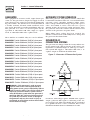
Figure 3 represents a single-phase, 3-wire generator AC
connection system. The stator assembly in this system
consists of a pair of stationary windings, with two leads
brought out of each winding. Each single winding can
supply 120 volts AC, 60 Hertz. When the two windings
are connected in series, a 240 volts, 60 Hertz AC output
results. Typically the two “hot” leads in the circuit are
Wires No. 11 and 44. The “Neutral” leads are the junc-
tion of Wires 22 and 33.
Figure 3 - Generator AC Connection System
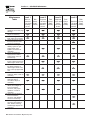
MAIN CIRCUIT BREAKER
The generator’s main circuit breaker is included with the unit as
shipped from the factory. The breaker for each unit is described in
Figure 5 below.
GENERATOR FUEL SYSTEM
Your unit has been factory tested and adjusted using a
natural gas fuel system. If propane (LP) gas is pre-
ferred, contact an authorized service dealer.
WARNING: Gaseous fuels such as natural and LP
(propane) gas are highly explosive. Even the slightest
spark can ignite such fuels and cause an explosion. No
leakage of fuel is permitted. Natural gas, which is lighter
than air, tends to collect in high areas. LP gas is heavier
than air and tends to settle in low areas.
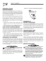
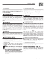
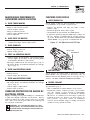
ENGINE PROTECTIVE DEVICES
The engine has several safety switches which cause the
engine to automatically shut down under the following
conditions: low oil pressure, high coolant temperature,
engine overspeed, low coolant level or overcrank.
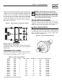
LOW OIL PRESSURE SWITCH:
This switch is normally-closed (N.C.) but is held open
by engine oil pressure during engine running. Should
operating oil pressure drop below about 8-10 psi (55-68
kPa), the switch contacts close and the engine shuts
down automatically (Figure 4).
Figure 4 - Low Oil Pressure Switch
Section 1 - General Information
Guardian Liquid-cooled 10 kW, 15 kW, 20 kW and 25 kW Generators
Model Rating Phase Actual Current C/B Rating* % over rating Circuit Breaker
004090-2 10,000 1 41.7 50 120% 50A BQ2
004091-2 10,000 3 30.1 40 133% 40A BQ3
004124-1 10,000 1 41.7 50 120% 50A BQ2
004125-1 10,000 3 30.1 40 133% 40A BQ3
004092-2 15,000 1 62.5 70 112% 70A BQ2
004093-2 15,000 3 45.2 60 133% 60A BQ3
004126-1 15,000 1 62.5 70 112% 70A BQ2
004127-1 15,000 3 45.2 60 133% 60A BQ3
004094-2 20,000 1 83.3 90 108% 90A BQ2
004095-2 20,000 3 60.2 70 116% 70A BQ3
004128-1 20,000 1 83.3 90 108% 90A BQ2
004096-2 25,000 1 104.2 125 120% 125A BQ2
004097-2 25,000 3 75.3 90 120% 90A BQ3
004130-1 25,000 1 104.2 125 120% 125A BQ2
004131-1 25,000 3 75.3 90 120% 90A BQ3
004474-0 25,000 1 104.2 125 120% 125A BQ2
004475-0 25,000 1 104.2 125 120% 125A BQ2
* Amp Rating of C/B structured under model.
Figure 5 - Main Circuit Breaker

6 Generac
®
Power Systems, Inc.
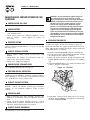
HIGH COOLANT TEMPERATURE SWITCH:
Normally open (N.O.) thermostatic switch has sensing
tip which is immersed in captive coolant. Should
coolant temperature exceed about 230°F (110°C), the
switch contacts close, which causes the engine to shut
down automatically (Figure 6).
Figure 6- High Coolant Temperature Switch
LOW COOLANT LEVEL SWITCH:
Should engine coolant level drop below the level of the
high coolant temperature switch, it is possible for the
engine to overheat without automatic shutdown. To
prevent such overheating without automatic shut down,
the engine has a low coolant level sensor. If the engine
coolant drops too low, the engine automatically shuts
down (Figure 7).
Figure 7 - Low Coolant Level Sensor
OVERSPEED SHUTDOWN:
The CMA circuit board on liquid cooled units receives
AC frequency (rpm) signals directly from the stator AC
power windings, via sensing leads S15 and S16. Should
AC frequency exceed about 72 Hz, circuit board action
will automatically shutdown the engine (Figure 8).
*Rated power of generator is subject to and limited by
such factors as ambient temperature, altitude, engine
condition, and other factors. Engine power will decrease
about 3.5% for each 1000 feet above sea level and will
decrease an additional 1% for each 10°F above 60°F.
Maximum output power of the generator is limited by
maximum engine power.
Section 1 — General Information
Guardian Liquid-cooled 10 kW, 15 kW, 20 kW and 25 kW Generators
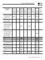
SPECIFICATIONS
GENERATOR SPECIFICATIONS
3-Phase 1-Phase
Mode
l 004097 004095 004093 004091 004096† 004094 004092 004090
004131 004127 004125 004130† 004126 004128 004124
*Rated Max. Cont.
AC Power Output (kW) 25 20 15 10 25 20 15 10
Rated Voltage (volts) 120/240 120/240
Rated Max. Cont.
Current @ 240 V, 1Ø N/A N/A N/A N/A 104.2 83.3 62.5 41.7
Current @ 240 V, 3Ø 75.3 60.2 45.2 30.1 N/A N/A N/A N/A
No. of Rotor Poles 2 4 2 4
Driven Speed of Rotor 3600 3600 1800 1800 3600 3600 1800 1800
Rotor Excitation System Direct excited brush type system
Type of Stator 12 wire reconnectable
Rotor/Stator Insulation Class F
† Models 004474 & 004475 has same specifications
as models 004096 & 004130 below.

Figure8-ControlModule Assembly Circuit Board
OVERCRANK SHUTDOWN:
After 90 seconds of crank-rest cycles, this function ends
cranking if the engine fails to start in that 90-second
span.
DC FUSE
This clearly labeled fuse is located on the front panel of
the control system. It protects the panel wiring and
components from damaging overload. Always remove
this fuse before commencing work on the generator.
The unit will not start or crank if the fuse is blown.
Replace the fuse with one of the same size, type, and rat-
ing. Generac normally uses an AGC fuse rated at 30
amps.
UNPACKING
UNPACKING PRECAUTIONS:
Handle shipping cartons and crates with care. Use care
to avoid damage from dropping, bumping, collision, etc.
Store and unpack cartons with the proper side up, as
noted on the shipping carton.
INSPECTION:
After unpacking, carefully inspect the generator for any
damage that may have occurred during shipment. If
loss or damage is noted at the time of delivery, have the
person(s) making delivery note all damage on the freight
bill or affix his signature under the consignor’s memo of
loss or damage.
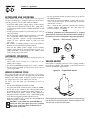
LIFTING THE GENERATOR
WARNING: When lifting or hoisting equipment is used,
be careful not to touch overhead power lines. The
generators weight of more than 900 pounds requires
proper tools, equipment, and qualified personnel to be
used in all phases of handling and unpacking.
SPECIFICATIONS
ENGINE SPECIFICATIONS
Make................................................................................Mitsubishi
Displacement ................................................92 inches
3
(1.5 liters)
Cylinder Arrangement........................................................4, in-line
Valve Arrangement..................................................Overhead Cam
Firing Order..........................................................................1-3-4-2
Number of Main Bearings ............................................................5
Compression Ratio ................................................................9 to 1
No. of Teeth on Flywheel ..........................................................104
Ignition Timing
at 1800 rpm ....................................................35 degrees BTDC
at 3600 rpm ....................................................43 degrees BTDC
Spark Plug Gap ....................................................0.020-0.025 inch
Recommended Spark Plugs
Champion ......................................................................RN11YC4
Oil Pressure......................................................................30-50 psi
Crankcase Oil Capacity..........................4.0 U.S. quarts (3.8 liters)
Recommended Engine Oil..........................................SAE 15W-40
Type of Cooling System ....................Pressurized, closed recovery
Cooling Fan ................................................................Pusher Type
Cooling System Capacity ........................2 U.S. gallons (7.6 liters)
Recommended Coolant..............................Use a 50-50 mixture of
ethylene glycol base.
FUEL CONSUMPTION
Models 004096, 004097, 004130, 004131, 004474, 004475
Using Natural Gas ....................................441 cu. ft. per hour
Using LP Gas ........................175 cubic ft.(4.8 gal.) per hour
Models 004094, 004095, 004128
Using Natural Gas ....................................359 cu. ft. per hour
Using LP Gas ........................143 cubic ft. (4.0 gal.) per hour
Model 004092, 004093, 004126, 004127
Using Natural Gas ....................................277 cu. ft. per hour
Using LP Gas ........................110 cubic ft.(3.1 gal.) per hour
Models 004090, 004091, 004124, 004125
Using Natural Gas ....................................195 cu. ft. per hour
Using LP Gas ..........................77 cubic ft. (2.2 gal.) per hour
NOTE:
Fuel consumption is given at rated maximum con-
tinuous power output when using natural gas rated
at 1000 Btu per cubic foot; or LP gas rated 2520
Btu per cubic foot. Actual fuel consumption
obtained may vary depending on such variables as
applied load, ambient temperature, engine condi-
tions and other environmental factors.
Section 1 — General Information
Guardian Liquid-cooled 10 kW, 15 kW, 20 kW and 25 kW Generators
Generac
®
Power Systems, Inc. 7

8 Generac
®
Power Systems, Inc.
TORQUE SPECIFICATIONS
Cylinder Head ......................................15 (+ 90° + 90°) ft.lb.
Intake Manifold ..........................................................13 ft.lb.
Exhaust Manifold ......................................................13 ft.lb.
ENGINE OIL RECOMMENDATIONS
The unit has been filled with 15W-40 engine oil at the
factory. Use a high-quality detergent oil classified “For
Service CC, SD, SE, SF.” Detergent oils keep the engine
cleaner and reduce carbon deposits. Use oil having the
following SAE viscosity rating, based on the ambient
temperature range anticipated before the next oil
change:
CAUTION: Any attempt to crank or start the
engine before it has been properly serviced with
the recommended oil may result in an engine
failure.
COOLANT RECOMMENDATIONS
Use a mixture of half low silicate, ethylene glycol base
anti-freeze and half soft water. Cooling system capacity
is about 8 U.S. quarts (8.5 liters). Use only soft water
and only low silicate anti-freeze. If desired, add a high
quality rust inhibitor to the recommended coolant mix-
ture. When adding coolant, always add the recom-
mended 50-50 mixture.
Do not use any chromate base rust inhibitor with eth-
ylene glycol base anti-freeze or chromiumhydroxide
(“green slime”) forms and will cause overheating.
Engines that have been operated with a chromate base
rust inhibitor must be chemically cleaned before
adding ethylene glycol base anti-freeze. Using any
high silicate anti-freeze boosters or additives will also
cause overheating. We also recommend that you DO
NOT use any soluable oil inhibitor for this equipment.
BEFORE INSTALLATION
Before installing this equipment, check the ratings of
both the generator and the transfer switch. Read
“Emergency Isolation Method” and “Total Circuit
Isolation Method” in the installation manual (Part No.
079699).
The generator’s rated wattage/amperage capacity must
be adequate to handle all electrical loads that the unit
will power. You may have to group the critical (essential)
loads together and wire them into a separate “emer-
gency” distribution panel.
This generator can be installed in conjunction with a
standard Generac “GTS” type transfer switch, if
desired.
The standard transfer switch has no sensing or con-
trolling circuit boards. Instead, the generator control
console houses a “Control Module Assembly”, which
controls all phases of operation, including engine start
up and load transfer.
Section 1 — General Information
Guardian Liquid-cooled 10 kW, 15 kW, 20 kW and 25 kW Generators
Temperature Oil Grade (Recommended)
Above 80° F (27° C) SAE 30W or 15W-40
32° to 80° F (-1° to 27° C) SAE 20W-20 or 15W-40
Below 32° F (0° C) SAE 10W or 15W-40

Generac
®
Power Systems, Inc. 9
If an open bottom is used, the engine-generator is
to be installed over non-combustible materials
and should be located such that combustible
materials are not capable of accumulating under
the generator set.
Only qualified, competent installation contractors or
electricians thoroughly familiar with applicable codes,
standards and regulations should install this standby
electric power system. The installation must comply
strictly with all codes, standards and regulations per-
taining to the installation.
After the system has been installed, you must not do
anything that might render the installation in noncom-
pliance with such codes, standards and regulations.
NOTE:
For more information about the installation of a stand-
by system, you can order Engine-Generator Standby
Electric Power Systems Installer’s Guide and
Reference Manual (part #046622) from your Generac
Authorized Service Dealer.
NFPA STANDARDS
The following published standards booklets pertaining
to standby electric systems are available form the
National Fire Protection Association (NFPA),
Batterymarch Park, Quincy, MA 02269:
• NFPA No. 37, STATIONARY COMBUSTION ENGINES
AND GAS TURBINES.
• NFPA No. 76A, ESSENTIAL ELECTRICAL SYSTEMS
FOR HEALTH CARE FACILITIES.
• NFPA No. 220, STANDARD TYPES OF BUILDING
CONSTRUCTION
• NFPA No. 68, GUIDE FOR EXPLOSION VENTING
• NFPA No. 70, NATIONAL ELECTRICAL CODE.
• NFPA No. 30, FLAMMABLE AND COMBUSTIBLE
LIQUIDS CODE.
• NFPA No. 10, INSTALLATION, MAINTENANCE AND
USE OF PORTABLE FIRE EXTINGUISHERS.
OTHER PUBLISHED STANDARDS
In addition to NFPA standards, the following informa-
tion pertaining to the installation and use of standby
electric systems is available:
• Article X, NATIONAL BUILDING CODE, available
from the American Insurance Association, 85 John
Street, New York, N.Y. 10038.
• AGRICULTURAL WIRING HANDBOOK, obtainable
from the Food and Energy Council, 909 University
Avenue, Columbia, MO, 65201.
• ASAE EP-364.2, INSTALLATION AND MAINTE-
NANCE OF FARM STANDBY ELECTRIC POWER,
available from the American Society of Agricultural
Engineers, 2950 Niles Road, St. Joseph, MI 49085.
• A52.1, AMERICAN NATIONAL STANDARD FOR
CHIMNEYS, FIREPLACES AND VENTING SYS-
TEMS, available from the American National
Standard Institute, 1430 Broadway, New York, N.Y.
10018.
BASIC STANDBY ELECTRIC SYSTEM
Figure 2.1 shows a schematic diagram of a basic stand-
by electric system. Both the UTILITY power supply and
the STANDBY (generator) output are connected to an
approved transfer switch. The transfer switch is
required by electrical code and serves the following
functions:
• Permits the LOAD circuits to be connected to only one
power supply at a time.
• Prevents electrical backfeed between the generator
and the UTILITY power circuits.
Notice that both the STANDBY and the UTILITY power
supplies to the transfer switch are protected against
overload by a main line circuit breaker.
NOTE:
Generac recommends the use of a Generac power
systems “GTS” type transfer switch in conjunction
with this generator.
Figure 2.1 – Basic Standby Electric System
◆
◆
Section2—Installation
Guardian Liquid-cooled 10 kW, 15 kW, 20 kW and 25 kW Generators
STANDBY GENERATOR INSTALLATION
Connecting this generator to an electrical system normally supplied by an electric utility shall be by
means of a transfer switch (such as the Generac “GTS” type transfer switch), so as to isolate the electric
system from the utility distribution system when the generator is operating. Failure to isolate the
electric system by these means will result in damage to the generator and may also result in injury
or death to utility workers due to backfeed of electrical energy.

10 Generac
®
Power Systems, Inc.
EMERGENCY CIRCUIT
ISOLATION METHOD
This prevents overloading the generator by keeping elec-
trical loads below the wattage/amperage capacity of the
generator. If the generator is powering only critical
loads, within the wattage/amperage capacity, during util-
ity power outages, you might consider using the emer-
gency circuit isolation method.
Critical electrical loads are grouped together and wired
into a separate “Emergency Distribution Panel.” Load
circuits powered by that panel are within the
wattage/amperage capacity of the generator set. When
this method is used, it is difficult to overload the gener-
ator. The transfer switch must meet the following
requirements:
• It must have an ampere rating equal to the total
amperage rating of the emergency distribution panel
circuit.
• Have it installed between the building’s main distribu-
tion panel and the emergency distribution panel.
TOTAL CIRCUIT ISOLATION METHOD
When a generator capable of powering all electrical
loads in the circuit is to be installed, you may use the
“Total Circuit Isolation Method.” It is possible for the
generator to be overloaded when this isolation method
is employed. The following apply to the transfer switch
in this type of system.
• Ampere rating of the transfer switch must equal the
ampere rating of the normal incoming utility service.
• The transfer switch is installed between the utility
service entrance and the building distribution panel.
GROUNDING THE GENERATOR
The National Electrical Code requires the frame and
external electrically conductive parts of this equipment
to be properly connected to an approved earth ground
and/or grounding rods. For that purpose, a GROUND
LUG (Figure 2.2) is provided on the generator mounting
base. Consult a qualified electrician for grounding
requirements in your area. Grounding procedures must
meet local regulations.
Do not connect the ground wire to any pipe that
carries a flammable or explosive substance – FIRE
or an EXPLOSION may result.
Proper grounding helps protect personnel against electri-
cal shock in the event of a ground fault condition in the
generator or in connected electrical devices. In addition,
grounding helps dissipate static electricity that often
builds up in ungrounded devices.
Figure 2.2 – Generator Grounding Lug (typical)
GENERATOR AC
NEUTRAL CONNECTIONS
Generac uses an UNGROUNDED AC neutral. Grounding
is recommended only at the main service entrance. If the
neutral wire is grounded and one of the phase loads
becomes grounded, the excessive current opens the load
circuit breaker or collapses the generator field. The actu-
al result depends on the electrical characteristics of the
particular installed generator.
TRANSFER SWITCH START
SIGNAL CONNECTIONS
If your generator is to be installed with an automatic
transfer switch, such as a Generac GTS-type switch, it
will be necessary to connect the two-wire start
control system.
Connect the two-wire start signal from the automatic
transfer switch to the automatic start connection, which is
located in the right hand corner inside the control panel.
Match wires 178 and 183 in the transfer switch to 178
and 183 on the terminal strip in the control panel. The
conductors for the two-wire start circuit must be in their
own conduit.
BATTERY INSTALLATION
Standby generators installed with automatic trans-
fer switches will crank and start automatically
when normal (utility) source voltage is removed or
is below an acceptable preset level. To prevent
such automatic start-up and possible injury to per-
sonnel, do not connect battery cables until you are
certain that normal source voltage at the transfer
switch is correct and you are ready to place the
system into operation.
Storage batteries give off explosive hydrogen gas.
This gas can form an explosive mixture around
the battery for several hours after charging. The
slightest spark can ignite the gas and cause
Section2—Installation
Guardian Liquid-cooled 10 kW, 15 kW, 20 kW and 25 kW Generators

Generac
®
Power Systems, Inc. 11
an explosion. Such an explosion can shatter the bat-
tery and cause blindness or other injury. Any area that
houses a storage battery must be properly ventilated.
Do not allow smoking, open flame, sparks or any spark
producing tools or equipment near the battery.
Battery electrolyte fluid is an extremely caustic
sulfuric acid solution that can cause severe burns.
Do not permit fluid to contact eyes, skin, clothing,
painted surfaces, etc. Wear protective goggles,
protective clothing and gloves when handling a
battery. If you spill the fluid, flush the affected
area immediately with clear water.
Do not dispose of the battery in a fire. The
battery is capable of exploding.
Do not open or mutilate the battery. Released
electrolyte can be toxic and harmful to the skin
and eyes.
The battery represents a risk of high short circuit
current. When working on the battery, always
remove watches, rings or other metal objects, and
only use tools that have insulated handles.
VENTED BATTERIES
The electrolyte is a dilute sulfuric acid that is
harmful to the skin and eyes. It is electrically con-
ductive and corrosive. The following procedures
are to be observed:
• Wear full eye protection and protective clothing,
• Where electrolyte contacts the skin, wash it off
immediately with water,
• Where electrolyte contacts the eyes, flush thoroughly
and immediately with water and seek medical atten-
tion, and
• Spilled electrolyte is to be washed down with an acid-
neutralizing agent. A common practice is to use a
solution of one pound (500 grams) bicarbonate of
soda to one gallon (4 liters) of water. The bicarbonate
of soda solution is to be added until the evidence of
reaction (foaming) has ceased. The resulting liquid is
to be flushed with water and the area dried.
Lead acid batteries present a risk of fire because
they generate hydrogen gas. The following proce-
dure are to be followed:
• DO NOT SMOKE when near batteries,
• DO NOT cause flame or spark in battery area, and
• Discharge static electricity from body before touching
batteries by first touching a grounded metal surface.
Servicing of batteries is to be performed or supervised
by personnel knowledgeable of batteries and the
required precautions. Keep unauthorized personnel
away from batteries.
For recommended batteries, see “Specifications.” All
batteries must be at 100 percent state-of-charge before
they are installed on the generator.
When using maintenance-free batteries, it is not neces-
sary to check the specific gravity or electrolyte level.
Have these procedures performed at the intervals spec-
ified in Section 4, “Maintenance.” A negative ground sys-
tem is used. Battery connections are shown on the
wiring diagrams. Make sure all batteries are correctly
connected and terminals are tight. Observe battery
polarity when connecting batteries to the generator set.
Note:
Damage will result if the battery connections are
made in reverse.
PREPARATION BEFORE START-UP
The instructions in this section assume that the standby
generator has been properly installed, serviced, tested,
adjusted and otherwise prepared for use by a competent,
qualified installation contractor. Be sure to read the
“Safety Rules” on Pages 2 and 3, as well as all other safe-
ty information in this manual, before attempting to
operate this (and related) equipment.
PRIOR TO INITIAL START-UP
Prior to initially starting the generator, it must be
properly prepared for use. Any attempt to crank
or start the engine before it has been properly
serviced with the recommended types and quanti-
ties of engine fluids (oil, coolant, fuel, etc.) may
result in an engine failure.
Before starting the generator for the first time, the
installer must complete the following procedures. For
follow-up maintenance information and/or service inter-
vals, please refer to Section 4, “Maintenance.”
Transfer Switch
If this generator is used to supply power to any electri-
cal system normally powered by an electric utility, the
National Electrical Code requires that a transfer switch
be installed. The transfer switch prevents electrical
backfeed between two different electrical systems.
(For additional information, see the applicable transfer
switch manual for this unit.) The transfer switch, as
well as the generator and other standby components,
must be properly located and mounted in strict compli-
ance with applicable codes, standards and regulations.
▼
◆
Section2—Installation
Guardian Liquid-cooled 10 kW, 15 kW, 20 kW and 25 kW Generators

12 Generac
®
Power Systems, Inc.
Fuel System
Make sure the fuel supply system to the generator (a)
delivers the correct fuel at the correct pressure and (b)
is properly purged and leak tested according to code.
No fuel leakage is permitted. See “Specifications” (Page
7) for more information.
Generator Set Lubrication
Check the engine crankcase oil level before operating
and add oil to the proper level – the dipstick “FULL”
mark. Never operate the engine with the oil level below
the dipstick “ADD” mark. See “Specifications” (Page 7)
and “Engine Oil Recommendations” (Page 8).
NOTE:
This engine is shipped from the manufacturer with
15W-40 oil. This oil should be changed after 30
hours of operation.
Engine Coolant
Have the engine cooling system properly filled with the
recommended coolant mixture. Check the system for
leaks and other problems. See “Specifications” (Page 7)
and “Coolant” (Page 8).
Belt Tension
Check the engine fan belt tension and condition prior to
placing the unit into service and at recommended
intervals. Belt tension is correct when a force of approx-
imately 22 pounds (10 kg), applied midway between
pulleys, deflects the belt about 3/8- to 5/8-inch
(10 to 16 mm).
Electrical System
Make sure the generator is properly connected to an
approved earth ground and/or ground rod.
Make sure the generator battery is fully charged, proper-
ly installed and interconnected, and ready for use.
Check to ensure that there are no loose electrical con-
nections. Restrain any loose wires to keep them clear of
any moving generator set components.
USING A STANDARD “GTS” TRANSFER
SWITCH
When required, the pre-packaged standby generator
can be installed with a standard Generac “GTS” type
automatic transfer switch.
When you use a standard GTS type transfer switch, it
controls automatic operation and automatic transfer as
follows:
• Solid state circuits in the transfer switch monitor util-
ity power source voltage.
• When utility source voltage drops below a pre-set
level, transfer switch action closes the circuit. The
engine then cranks and starts as controlled by the
pre-packaged generator’s Control Module circuit
board.
• After the engine starts and when the generator AC
output voltage and frequency have reached a pre-set
value, transfer switch circuits signal the transfer
switch main contacts to actuate to the “Standby”
power source side. Generator AC output then powers
load circuits.
• When the utility power source voltage is restored
above a pre-set level, transfer switch solid state cir-
cuits signal the switch main contacts to move back to
their utility power source side.
• Following re-transfer back to the utility power source
side, transfer switch circuit board action opens the
circuit. Engine then shuts down.
NOTE:
If your generator is installed in conjunction with a
standard GTS type transfer switch, refer to the
applicable transfer switch manual for exact oper-
ating parameters and timing sequences.
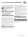
CONTROL CONSOLE COMPONENTS
The components of a water-cooled generator control
console (Figure 8) are as follows:
Figure 8 - Water-Cooled Generator Panel
AC VOLTMETER:
The voltmeter displays generator AC output voltage dur-
ing operation. Voltage is regulated by a solid state volt-
age regulator and is proportional to AC frequency. Refer
to your unit’s DATA PLATE for rated AC voltage.
▼ ▼ ▼ ▼ ▼
Section3—Installation
Guardian Liquid-cooled 10 kW, 15 kW, 20 kW and 25 kW Generators

Generac
®
Power Systems, Inc. 13
AC AMMETER:
Indicated current draw of connected electrical loads
during operation. DO NOT EXCEED YOUR UNIT’S
RATED MAXIMUM CONTINUOUS CURRENT. Refer to
the unit DATA PLATE.
AC FREQUENCY METER:
Indicates generator AC output frequency in “Hertz”
(cycles per second). Frequency is proportional to engine
speed. Units with a 4-pole rotor supplies 60 Hertz at
1800 rpm. Units with a 2-pole rotor supplies 60 Hz at
3600 rpm. Frequency reading with no electrical loads
connected (no-load condition) should be between 59-61
Hertz.
DC VOLTMETER:
The generator is equipped with a belt-driven DC
alternator, which maintains battery state of charge when
the engine operates. The Control Module Assembly also
incorporates a trickle charge circuit which maintains
battery state of charge during non-operating periods.
Battery voltage should read about 12.5 to 14.5 volts DC.
A low battery voltage indicates the battery is
discharging.
HOURMETER:
Indicates time the engine-generator has operated, in
hours and tenths of hours. Use the hourmeter along
with the periodic maintenance schedule for your gener-
ator set.
AUTO/OFF/MANUAL SWITCH:
Use this 3-position switch as follows:
• Set the switch to “Auto” for fully automatic operation.
See “Automatic Operation”.
• Set switch to “Manual” position to crank and start the
generator engine.
• Set switch to “Off” position to shut down an operat-
ing engine. With “Off” selected, operation will not be
possible.
DANGER! With switch set to "auto", engine can
crank and start suddenly without warning. Such
automatic start up normally occurs when utility
source voltage drops below a pre-set level. To
prevent possible injury that might be caused by
such sudden starts, set AUTO/OFF/MANUAL
switch to "off" before working on or around the
unit. Then, place a "do not operate" tag on con-
trol console.
FAULT INDICATOR LAMP:
Lamp goes ON when one or more of the following
engine faults occurs and when engine shuts down.
• Low oil pressure • Overcrank
• High coolant temperature • Overspeed
• Low coolant level
30 AMP FUSE:
Fuse protects the control console’s DC control circuit
against electrical overload. If the fuse has melted open
because of an overload, engine cranking and startup
cannot occur. Should you need to replace the fuse, use
only an identical 30-amp replacement fuse. (Type AGC)
7.5 AMP INLINE FUSE:
A 7.5 Amp inline fuse has been added to the wire har-
ness of all units starting in the second half of 2001. This
inline fuse is connected in the 15A line that runs
between the Auto/Off/Manual switch and position 10 of
the 76009A PCB. This fuse protects the start, fuel, field
boost, and transfer outputs from the PCB and will open
if there is excessive current draw on any one of these
outputs.
NOTE:
This fuse will not remove the + battery input
power from the PCB when it opens. This means the
exercise timer will not be reset. If this fuse does
open, carefully check the wiring to the start, fuel,
field boost and transfer outputs before replacing
the fuse.
METER READING SELECTOR SWITCH:
Switch permits you to select either line-to-line or
line-to-neutral voltage and amperage readings on the
console AC voltmeter and AC ammeter.
SET EXERCISE TIME SWITCH:
Switch allows you to program the generator to start and
exercise automatically. “See Weekly Exercise Cycle.”
MANUAL TRANSFER AND START UP
To transfer electrical loads to the “Standby” (generator)
power source side and start the engine manually, refer
to the Owner’s Manual of your particular transfer
switch.
Section 3 - Operation
Guardian Liquid-cooled 10 kW, 15 kW, 20 kW and 25 kW Generators

14 Generac
®
Power Systems, Inc.
RETRANSFER AND SHUTDOWN
When utility power source voltage has been restored,
electrical loads may be transferred back to that source
and the generator can be shut down as follows:
• Verify that utility power supply voltage to the transfer
switch has been positively turned “Off,” using what-
ever means provided (such as utility main line circuit
breaker).
• Set the generator’s main circuit breaker to its “Off” or
“Open” position.
• Let the generator engine run at no-load for a few min-
utes, to stabilize internal unit temperatures.
• On the generator console, set the Auto-Off-Manual
switch to “Off”. Wait for engine to come to a com-
plete stop.
• For transfer to utility position, refer to the Owner’s
Manual of your particular transfer switch.
• Turn on the utility power supply to the transfer
switch, using whatever means provided (such as a
utility main line circuit breaker). The utility power
source now powers the loads.
AUTOMATIC OPERATION
To set the system for fully automatic operation, proceed
as follows:
• Check that load circuits are connected to the
utility power supply.
• Set the Auto/Off/Manual switch to its “Auto” position.
• Set the generator main circuit breaker to its “On” or
“Closed” position.
WEEKLY EXERCISE CYCLE
The generator will start and exercise once every 7 days.
During this weekly exercise, the unit runs for about 20
minutes and shuts down. Transfer of loads to genera-
tor output does not occur during the exercise.
To select day and time for exercising, proceed as
follows:
• Set the Auto/Off/Manual switch to OFF.
• Set generator main circuit breaker to OFF or OPEN.
• Locate the rocker switch on the control panel identi-
fied with the words “Set Exercise Time” (Figure 9).
• Push “Set Exercise Time” switch to ON position for
20 to 30 seconds and then release. Switch will spring
back into its original position when released.
• Wait 30 seconds before setting the Auto/Off/Manual
switch to “AUTO” position.
CAUTION: If you switch the Auto/Off/Manual
switch too soon, the engine may start. If engine
does start, it will shut down automatically in
about two (2) minutes.
• Set the generator main circuit breaker to its ON or
CLOSED position.
• Generator is now programmed to start and exercise
every 7 days thereafter, on day and time of day the
switch was actuated.
• Place a sign on the generator control panel and the
transfer switch, indicating the day and time the
generator will be exercising.
NOTE:
If battery terminals are disconnected or control
panel fuse is removed, the exercise timer needs to
be reset for correct automatic exercise operation.
Figure 9 - “Set Exercise” Switch
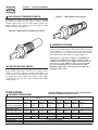
ENGINE HEATER
Your Generac standby generator comes equipped with a
block heater (Figure 10), similar to the block heaters
used in automotive applications.
Figure 10 - Engine Block Heater
Refer to applicable wiring diagram(s) and electrical schematic(s) at
back of manual for wiring connections. Customer supplies a 120V
15A Utility fed circuit for the block heater.
Section 3 — Operation
Guardian Liquid-cooled 10 kW, 15 kW, 20 kW and 25 kW Generators

Generac
®
Power Systems, Inc. 15
MAINTENANCE PERFORMED BY
AUTHORIZED SERVICE FACILITIES
A. EVERY THREE MONTHS
1.Check battery state of charge and condition.
2.Inspect and test fuel system.
3.Check transfer switch.
4.Inspect exhaust system.
5.Check engine ignition system.
6.Check fan belts.
B. ONCE EVERY SIX MONTHS
1.Test Engine Safety Devices (low oil pressure, low
coolant level, high coolant temperature).
C. ONCE ANNUALLY
1.Test engine governor; adjust or repair, if needed.
2.Clean, inspect generator.
3.Flush cooling system.
D. FIRST 100 OPERATING HOURS
1.Change engine oil and oil filter. (After initial change,
service engine oil and filter at 150 operating hours
or 6 months, whichever comes first.)
2.Retorque cylinder head. (See Torque Specs, page 7.)
3.Retorque intake and exhaust manifold. (See Torque
Specs, page 7.)
E. EVERY 500 OPERATING HOURS
1.Service air cleaner.
2.Check starter.
3.Check engine DC alternator.
F. EVERY 800 OPERATING HOURS
1.Retorque cylinder head. (See Torque Specs, page 7.)
2.Retorque intake and exhaust manifold. (See Torque
Specs, page 7.)
3.Check engine compression.
4.Check valve clearance.
OVERLOAD PROTECTION FOR ENGINE DC
ELECTRICAL SYSTEM
Engine cranking, start up and running are controlled by
a solid state Engine Controller circuit board. Battery
voltage is delivered to that circuit board via a 30 amp
fuse. These overcurrent protection devices will open if
the circuit is overloaded.
CAUTION! If a circuit breaker opens or a fuse
element melts, you should find the cause of the
overload before resetting the circuit breaker or
replacing the fuse.
CHECKING FLUID LEVELS
CHECK ENGINE OIL
Check engine crankcase oil level (Figure 11) at least
every 20 hours of operation, or prior to use.
• Remove oil dipstick and wipe dry with a clean,
lint-free cloth.
• Install oil dipstick, then remove again.
• Oil should be between FULL and ADD marks.
• If oil level is below the dipstick ADD mark, remove oil
fill cap. Add the recommended oil to bring oil level
up to the FULL mark. DO NOT FILL ABOVE THE
“FULL” MARK. See page 6 for recommended oils.
Figure 11 - Oil Dipstick and Oil Fill Cap
c
ap
BATTERY FLUID
Check battery electrolyte fluid at least once weekly.
Fluid should cover separators in all battery cells. If
fluid level is low, add distilled water to cover tops of sep-
arators. DO NOT USE TAP WATER IN BATTERY.
ENGINE COOLANT
Check coolant level in coolant recovery bottle. See
Specifications, page 8
• Add recommended coolant mixture as necessary.
• Periodically remove radiator pressure cap to make
sure the coolant recovery system is functioning
properly. Coolant should be at bottom of radiator
filler neck. If coolant level is low, inspect gasket in
radiator pressure cap. Replace cap, if necessary. To
have pressure cap tested, contact an authorized
Generac Service Facility. Inspect cooling system and
coolant recovery system for leaks.
OIL FILL CAP
OIL DIPSTICK
Section 4 — Maintenance
Guardian Liquid-cooled 10 kW, 15 kW, 20 kW and 25 kW Generators

16 Generac
®
Power Systems, Inc.
MAINTENANCE OWNER/OPERATOR CAN
PERFORM
CHECK ENGINE OIL LEVEL
Refer to “Checking Fluid Levels” on page 15.
CHECK BATTERY
• Check battery fluid level each week as outlined under
“Check Fluid Levels”.
• Check battery cables for condition, tightness, corro-
sion or damage. Clean, tighten or replace as
necessary.
EXERCISE SYSTEM
Start the generator engine at least once every seven days
and let it run at least 20 minutes. See page 14, “Weekly
Exercise Cycle”.
INSPECT COOLING SYSTEM
• Inspect engine cooling system at least once each
month.
• Check hoses for damage, deterioration, leaks, etc.
Correct any discrepancies found.
• Check hose clamps for tightness.
CHECK ENGINE COOLANT LEVEL
See “Checking Fluid Levels” on page 15.
PERFORM VISUAL INSPECTION
Complete a thorough visual inspection of the entire
engine-generator monthly. Look for obvious damage,
loose, missing or corroded nuts, bolts and other fasten-
ers. Look for fuel, oil or coolant leaks.
INSPECT EXHAUST SYSTEM
Inspect the exhaust system at least once every three
months. Check all exhaust system pipes, mufflers,
clamps, etc. for condition, tightness, leaks, security,
damage.
CHECK FAN BELT
• Inspect fan belts every three months. Replace any
damaged, deteriorated, worn or otherwise defective
belt.
• Check fan belt tension. Thumb pressure, exerted
midway between pulleys, should deflect about 3/8 to
3/4 inch. Adjust belt tension as required.
INSPECT ENGINE GOVERNOR
Visually inspect electronic governor.
DANGER: Do not attempt to adjust the gover-
nor. Only qualified service facilities should
adjust the governor. Excessively high operating
speeds are dangerous and increase the risk of
personal injury. Low speeds impose a heavy
load on the engine when adequate engine
power is not available and may shorten engine
life. Correct rated frequency and voltage are
supplied only at the proper governed speed.
Some connected electrical load devices may be
damaged by incorrect frequency and/or voltage.
Only qualified service technicians should adjust
the governed speed.
CHANGING ENGINE OIL
Refer to maintenance performed by authorized service
facilities for engine oil and filter change frequencies.
Drain the oil while the engine is still warm from run-
ning. This means warm up the engine, shut it down and
drain immediately as follows:
1.Remove OIL DRAIN HOSE from its retaining clip.
2.Loosen and remove OIL DRAIN HOSE CAP. Drain
oil completely into suitable container.
3.When all oil has drained, install and tighten OIL
DRAIN HOSE CAP, and re-install into its retaining
clip.
4.Turn OIL FILTER (Figure 12) counterclockwise and
remove. Dispose of old filter.
Figure 12 - Oil Filter
5.Apply light coating of new engine oil to seal of new
oil filter. Install FILTER and tighten by hand only.
DO NOT OVERTIGHTEN.
OIL FILTER
Section 4 — Maintenance
Guardian Liquid-cooled 10 kW, 15 kW, 20 kW and 25 kW Generators

Generac
®
Power Systems, Inc. 17
6.Remove OIL FILL CAP (Figure 11, page 15). Add
recommended oil (see SPECIFICATIONS). DO NOT
FILL ABOVE THE DIPSTICK “FULL” MARK.
Crankcase oil capacity is 4.0 U.S. quarts (3.8 liters)
CAUTION: After refilling the crankcase with oil,
always check oil level on dipstick. NEVER
OPERATE ENGINE WITH OIL BELOW THE DIP-
STICK “ADD” MARK.
7.Start engine and check for oil leaks.
COOLANT CHANGE
Every year, have Authorized Service Facility drain, flush
and refill the cooling system. See SPECIFICATIONS
(page 8) for cooling system recommendations.
MISCELLANEOUS MAINTENANCE
CLEANING THE GENERATOR
Keep your generator as clean and as dry as possible.
Dirt and moisture that accumulates on internal genera-
tor windings have an adverse effect on insulation resist-
ance.
Periodically clean generator exterior surfaces. A soft
brush may be used to loosen caked on dirt. You can use
a vacuum system or dry, low pressure air to remove any
accumulations of dirt. The generator is housed inside
an all-weather enclosure, clean the enclosure with a
soft, damp cloth or sponge and water.
Once each year have the generator cleaned and inspect-
ed by an Authorized Service Facility. That facility will
use dry, low pressure air to clean internal windings.
Parts inside the control console should be cleaned and
inspected at this time as well.
Finally, have the insulation resistance of stator and
rotor windings checked. If insulation resistances are
excessively low, the generator may require drying.
BATTERY
All lead-acid storage batteries discharge when not in
use. Refer to specific instructions and warnings that
accompany your battery. If such information is not
available, observe the following precautions when
handling a battery:
• DO NOT use jumper cables and a booster battery to
crank or start the generator engine.
• DO NOT recharge a weak battery while it is installed
in the generator. Remove battery from generator and
recharge in a well-ventilated area, away from fuel
vapors, sparks, heat or flames.
• Battery electrolyte fluid is an extremely caustic
sulfuric solution that can cause severe burns. DO
NOT permit fluid to contact eyes, skin, clothing,
painted surfaces, wiring insulation, etc. If you spill
any battery fluid, flush the affected area with clear
water immediately.
• Always wear safety glasses, rubber apron and gloves
when handling a battery.
• Batteries give off explosive hydrogen gas while
charging. The gas can form an explosive mixture
around the battery for several hours after charging.
Any spark, heat or flames can ignite the gas and
cause an explosion which can shatter the battery,
causing blindness or other serious injury.
BATTERY REPLACEMENT
Generac uses these different types of vented batteries on
units ranging up to 400 kW. When replacing batteries,
use the same number and the type of battery that
follows:
Note:
The BCI number should be located directly
on the battery.
Section 4 — Maintenance
Guardian Liquid-cooled 10 kW, 15 kW, 20 kW and 25 kW Generators
Generac P/N BCI Group No. CCA
058665 27F 700 @ 0 deg. F

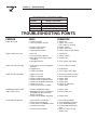
Section5—Troubleshooting
Guardian Liquid-cooled 10 kW, 15 kW, 20 kW and 25 kW Generators
PROBLEM CAUSE CORRECTION
Engine won’t crank. 1. 30 amp fuse blown. 1. Replace fuse.
2. Loose or corroded or defective 2. Tighten, clean or replace
battery cables as necessary.
3. Defective starter contactor. 3. Replace contactor.
4. Defective starter motor. 4. Replace starter motor.
5. Dead or Defective Battery. 5. Remove, change or replace battery.
Engine cranks but won't start 1. Out of fuel. 1. Replenish fuel.
2. Fuel solenoid (FS) is defective 2. Replace solenoid.
3. Open Wire #14 from Engine Control 3. Reconnect wire.
circuit board
4. Spark plugs defective. 4. Clean, regap or replace plugs.
Engine starts hard, runs rough. 1. Flame arrestor (air cleaner) plugged or 1. Clean or replace as needed.
damaged.
2. Plugged fuel line. 2. Unclog fuel line.
3. Defective spark plugs. 3. Clean, regap or replace plugs.
Engine starts then shuts down. 1. Engine oil level is low. 1. Check oil and add oil as needed.
2. Engine is overheated. 2. Check cooling system for leaks.
3. Defective Low Oil Pressure Switch 3. Replace switch.
4. Defective Coolant Temperature Switch 4. Replace switch.
5. Defective Control Module circuit board. 5. Replace board.
6. Coolant Level is Low. 6. Repair leak - Add coolant.
7. Defective Low Coolant Level Switch 7. Replace Switch.
Auto/Off/Manual Switch at OFF, 1. Defective Auto/Off/Manual switch 1. Replace switch.
engine continues to run 2. Open/disconnected wire #15A between 2. Reconnect/close wire.
Auto/Off/Manual switch and Control
Module circuit board.
3. Defective Control Module circuit board 3. Replace board.
No AC output from generator. 1. Check main line circuit breaker. 1. Reset to ON or CLOSED.
2. Check circuit breaker & fuses. 2. Reset and replace, if necessary.
3. Transfer switch set to NORMAL position 3. Set to GENERATOR position.
4. Generator internal failure. 4. Contact an Authorized Generac
facility.
5. Thermal circuit breaker open. 5. Auto-reset - Wait 5 min. and
attempt restart.
PERIODIC REPLACEMENT PARTS
Part Name Generac’s Part Number
Oil Filter # 0A45310244
Radiator Cap # 046627
Air Cleaner # 059402
Spark Plug # 0A45310275
TROUBLESHOOTING POINTS
Page is loading ...
Page is loading ...
Page is loading ...
Page is loading ...
Page is loading ...
Page is loading ...
Page is loading ...
Page is loading ...
Page is loading ...
Page is loading ...
Page is loading ...
Page is loading ...
Page is loading ...
Page is loading ...
Page is loading ...
Page is loading ...
Page is loading ...
Page is loading ...
Page is loading ...
Page is loading ...
Page is loading ...
Page is loading ...
Page is loading ...
Page is loading ...
Page is loading ...
Page is loading ...
Page is loading ...
Page is loading ...
Page is loading ...
Page is loading ...
Page is loading ...
Page is loading ...
-
 1
1
-
 2
2
-
 3
3
-
 4
4
-
 5
5
-
 6
6
-
 7
7
-
 8
8
-
 9
9
-
 10
10
-
 11
11
-
 12
12
-
 13
13
-
 14
14
-
 15
15
-
 16
16
-
 17
17
-
 18
18
-
 19
19
-
 20
20
-
 21
21
-
 22
22
-
 23
23
-
 24
24
-
 25
25
-
 26
26
-
 27
27
-
 28
28
-
 29
29
-
 30
30
-
 31
31
-
 32
32
-
 33
33
-
 34
34
-
 35
35
-
 36
36
-
 37
37
-
 38
38
-
 39
39
-
 40
40
-
 41
41
-
 42
42
-
 43
43
-
 44
44
-
 45
45
-
 46
46
-
 47
47
-
 48
48
-
 49
49
-
 50
50
-
 51
51
-
 52
52


Generac 004090-2, 004091-2, 004092-2, 004093-2, 004094-2, 004095-2, 004096-2, 004097-2, 004474-0 User manual
- Category
- Power generators
- Type
- User manual
Ask a question and I''ll find the answer in the document
Finding information in a document is now easier with AI
Related papers
-
Generac Portable Generator 0043736, 0046265 User manual
-
-
-
-
-
-
-
-
-
Other documents
-
Generac Power Systems Guardian 004988-1 User manual
-
-
-
-
Guardian Technologies 004988-4 User manual
-
-
Panasonic ER430-X8 Owner's manual
-
-
-