
Page is loading ...
Page is loading ...
Page is loading ...

GENERAL INFORMATION
62.9585.01_UL Page 3
I . GENERAL INFORMATION
1. INSTRUCTIONS FOR SAFETY AND USE
1.1 INSTALLATION AND INITIAL OPERATION
1.2 OWNER'S OBLIGATIONS
1.3 USE AS PRESCRIBED
1.4 SAFETY-CONSCIOUS WORKING
1.5 AFTER-SALES SERVICE AND REPAIR
2. TECHNICAL DATA
3. PACKAGING
All the packaging materials used are environmentally friendly.
They may burnt at an incineration plant or sent for recycling.
4. TESTS / CERTIFICATES
All electrical appliances are UL 197 tested.
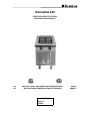
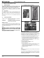
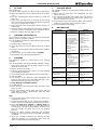
5. SPECIFICATION PLATE
The specification plate (E) is located in each case inside and
outside on the right of the operator panel (C) (Page 5 Fig. 5).
The serial number is marked on the type plate. The 8 digits
give following information:
Y last digit of the year of production
WW week of production
XXXXX running number
S The installation, adjustment and initial
operation of the appliance must be properly
carried out in accordance with the
manufacturer's instructions and may only be
done by an authorised specialist.
S Installations for the supply of electricity must be
carried out by qualified installers in accordance
with the specific national and local regulations.
They bear the responsibility.
S The appliance must not be placed in operation
until the user has become familiar with its
operation. The operating instructions and the
related safety precautions must be followed
precisely. Follow strictly the attention and
warning label indications on the appliances.
S The manager is responsible for ensuring that
all components relevant for safety are in
perfect working order at all times. The
operating condition of these components must
be examined by an authorized technician at
least once a year and any defects remedied if
required.
S The operator of this appliance is responsible
for total observation of the national regulations
concerning operating safety.
S Remain the manual for future reference.
S Closed containers (jars, cans, bottles, tubes,
etc.) must not be heated owing to the danger of
bursting and injuries.
S Spraying the appliance or its parts with a high-
pressure cleaning device may cause
malfunctions and is not to be done.
S The trough heating must not be switched
on if there is no oil in the trough or the oil
level has fallen below the minimum. Opera-
ting the fryer with too low oil level is a fire
risk.
S Food must be placed slowly in the heated
trough, to prevent the oil from bubbling over.
S Mounting a mixer tap near a fryer is prohibited,
since there is a great danger of explosions.
S When the oil trough temperature is high and
food with a high water content is to be fried, the
hot oil may froth up and spit out. Danger of
injury!
S Used oil has a lower ignition point and tends to
bubble up - Danger of injury!
S Oil must not be allowed to drain into the
discharge vessel or transported before it is
cooled down fully.
S For appliances with a downpipe, the hose
should lead into a drain opening which is cov-
ered by a grating such that it cannot be kicked
or tipped, or a drain gutter should run under-
neath the appliance.
S Devices on wheels set up in block configuration
must be checked before each start-up whether
the potential equalization is connected with the
neighbour equipment. The connection may be
done only by authorized technical personnel.
S Appliances on wheels must be fastened to the
building.
S In the event of a permanent fault which
interferes with operation, the appliance must be
switched off and disconnected from the power
supply.
S To perform maintenance and repairs contact
the factory, the factory representative or a local
service company.
S Repair, maintenance work and other
adjustments are only to be carried out by an
authorized specialist. The valid local and
national regulations must be observed. This
applies especially to safety and control
elements. Parts requiring replacement are only
to be replaced by original spare parts. A
service contract is recommended.
S Cleaning and maintenance must be done only
when the heating surfaces are cold. Do not use
inflammable liquids to clean the appliance.
S An obligatory service check is required
annually.
PNC
Appliances
Appliance type
Voltage
Width
Depth
Height
Trough
contents
Power
V
inch
mm
in kW
9CHG584093 WFWROFOOOO 208
19.7
35.4
35.4
500
900
900
6.1 gal
1 x 23 l
12.2
9CHG584094 WFXROFOOOO 240
13
9CHG584095 WFWROAOOOO 208 12.2
9CHG584096 WFXROAOOOO 240
13
9CHG584097 WFWUOFOOOO 208
31.5
35.4
35.4
800
900
900
3.7 gal
2 x 14 l
18.4
9CHG584098 WFXUOFOOOO 240
20.8
9CHG584099 WFWUOAOOOO 208 18.4
9CHG584100 WFXUOAOOOO 240
20.8

INSTALLATION INSTRUCTIONS
Page 4 62.9585.01_UL
II . INSTALLATION INSTRUCTIONS
1. INSTALLATION
The appliance is designed for connection to fixed lines. The
appliances are suitable for setting up as single appliances or as
a group of appliances. They can be set up freely in the room,
side by side, at the side and/or at the back against a wall.
Gaps between two appliances or appliance and sidewall
should be filled with a FDA approved silicone such as Samco
RTV103.
1.1 DISTANCES
If an appliance is set up next to or against temperature-sensi-
tive furniture or similar, a safety gap of approximately 6“ (15
mm) should be maintained or some form of heat insulation fit-
ted.
The walls must be made up of non-combustible material like
tiles or steel.
1.2 HEIGHT ADJUSTMENT
Appliance on feet.
D Turn the lower part of the feed to adjust the appliance high.
The feet are adjustable from 4“ to 8“ (100 to 200 mm). A high
of 8“ (200 mm) can be recommended and results in an appli-
ance high of 35,4“ (900 mm).
Note:
Adjustment of the legs shall provide an unobstructed
clearance of minimal 6“ (150 mm) and maximal 8“ (200
mm) beneath the unit due to sanitary and stability
aspects.
The lower part of the foot must not be unscrewed too far.
The exposure of threads is prohibited.
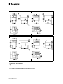
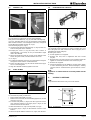
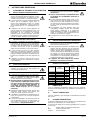
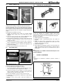
1.3 ASSEMBLING TWO APPLIANCES
The assembly kit contains three of each of the following:
caged nuts (1 / Fig.1) pre-assembled on the right-hand side of
the appliance, hexagonal screws M8x25 (1 / Fig.1), bolts with
retaining rings (2 / Fig.1) and mounting links (3 / Fig.1)
D Remove the control panels from both appliances as in 2.2
D Remove the front panels from both appliances as in 2.1
D Insert the bolts with the retaining rings (2 / Fig.1) from out-
side into the guide in the right-hand connecting plate.
D Keeping the screw (3 / Fig.1) loose, turn it until it is approx-
imately 5 mm deep in the caged nut.
Positioning the appliances:
D Place the appliances next to one other.
D Align for position and height.
Connect the appliances:
D Push the appliances together so that the bolts (1 / Fig.1)
engage in the guides of the appliance to be attached.
D Fit the mounting link (3 / Fig.1) into the inside of the second
appliance's left connecting plate.
D Tighten the screws.
Note
If required, the caged nuts can also be fitted on the other side
of the appliance.
The connection of two appliances (Fig 1c, arrow) must corre-
spond to the hygienic regulations respective the standard
NSF/ANSI 4. All resulting joints and seams in a splash zone
shall be sealed and smooth.
Appliance on feet: Alignment is carried out by screwing the
lower foot parts in or out.
Appliance on
steel plinth:
Irregularities or differences in height can
be equalized by inserting one or several
strips of chrome nickel steel.
a
b
c
Fig.1 Lateral connection
(1)
(2)
(1)
(2)
(2)
(3b)
(3a)
(3c)
(1)
(3)
(2)
1
(3c)

INSTALLATION INSTRUCTIONS
62.9585.01_UL Page 5
1.4 SIDEWALL (D)
The assembly kit contains two of each of the following:
hexagonal screws M8x25 (1 / Fig.1), bolts with retaining rings
(2 / Fig.1), mounting links (3 / Fig.1), hexagonal screws M8x16
with serrated washers and hexagonal nuts M8, hexagonal
screws M5 with serrated washers (4 / Fig.2)
and a fastening angle (5 / Fig.2).
D Insert the bolts with the retaining rings (2 / Fig.1a) from out-
side into the guide in the sidewall.
D Keeping the screw (1 / Fig.1a) loose, turn it until it is
approximately 5 mm deep in the pre-assembled caged
nuts in the sidewall.
D Attach the fastening angle (5 / Fig.2b) to the bottom of the
frame using the screws, serrated washers and nuts.
D (4 / Fig.2).
D Position the sidewall and screw it on from below using two
hexagonal screws and the serrated washers.
D Fit the mounting link (3 / Fig.1b) into the inside of the appli-
ance's connecting plate.
D Align the sidewall and firmly tighten all screws.
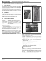
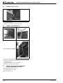
1.5 STEEL PLINTH
To assemble the plinth you will need:
• Right and left side plinth (1 / Fig.3).
• Plinth for the front and, for free-standing appliances, for the
rear also (2 / Fig.3).
D Push the side plinth (1 / Fig.3) onto the legs from front to
rear using the fastener. The larger gap (b / Fig.3) on the
fastener must be at the bottom.
D Affix the fasteners (3 / Fig.3) to the plinth (2 / Fig.3).
D The larger gap (b / Fig.3) on the fastener must be at the
bottom.
D Attach the plinth with the fasteners (3 / Fig.3) onto the feet.
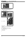
1.6 ASSEMBLING ON CASTORS
The assembly kit for mounting on castors contains two cross
bars (2/Fig.4a) each with a fixed rear wheel (1/Fig.4a) and a
turnable front wheel (3/Fig.4a).
Mounting the castors:
D Put the appliance on supports.
D Remove the feet; each is tightened with four screws
(Fig.4b).
D Bring the two cross bars into the correct position below the
appliance and fasten it with 8 screws arrows (Fig.4a).
D Remove the supports.
D Fasten the appliance to the building. Use the hole to attach
a chain descending from the wall (arrow/Fig.4c). Making
sure the chain is shorter than the gas and electric connec-
tions.
Note:
Appliances on wheels must be secured by fasten it to the
building.
2. ACCESS TO INTERIOR
Note:
Only authorized technicians may access the interior.
a
b
Fig.2 Assemblage of sidewall
a
b
Fig. 3 Plinth assembly
1
()
(5)
(4)
1
(3c)
1
()
(5)
(4)
(1)
(2)
(3)
b
b
1
(3c)
(1)
(2)
(3)
a
b
c
Fig.4 Assemblage on castors
Fig. 5 General view
1
()
(5)
(4)
1
(3c)
1
(3c)
1
3
1
3
D
D
B
C
E

INSTALLATION INSTRUCTIONS
Page 6 62.9585.01_UL
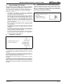
2.1 FRONT PANELS (A) and (B)
D Unscrew screws (1 or 3). Also, in the case of a built-in oven,
unscrew screws (2 and/or 4) on the inside of the oven.
D Pull the panel away forwards and downwards.
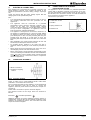
2.2 CONTROL PANEL (C)
D Remove the knob.
D Loosen the screws underneath (1 / Fig.7a) and remove the
base plate.
D Loosen the screws (2 / Fig.7b) and 3 / Fig.7c)
D Remove the panel.
2.3 OVEN, STORAGE SPACE, HOT CABINET
D Remove panels A, B and C.
D Undo screws (5).
D Pull out element.
D
Fig.6 Front panel
ab
Fig. 7 Control panel
c
(1)
1
(3c)
(1)
1
(3c)
(2)
(3)

INSTALLATION INSTRUCTIONS
62.9585.01_UL Page 7
4. ELECTRICAL CONNECTION
Each appliance is accompanied by a complete connection and
wiring diagram enclosed. This contains full details of the
technical specifications (electrical rating, voltage, amperage
etc.)
Check and ensure that the mains voltage agrees with the
voltage given on the specification plate.
N.B.:
• The corresponding arrangements must be made on-site for
the earthing connection and fuse protection for the
appliances.
• The appliance must be connected to a potential
equalization system with a minimum conductor cross-
section of 10 mm². The correspondingly marked
connection terminal must be used for this purpose. When
set up in block configuration, all appliances must be
interconnected as potential equalization.
• The appliance is designed for connection to fixed lines. If
the appliance is fitted directly to a masonry plinth without
an appliance plinth, the supply must be located at the
prescribed place. In this case, the protecting tube may not
protrude from the plinth. If a CNS base is used, the
protecting tube may not protrude more than 10 cm from the
floor.
• After installation, the shock-hazard protection for live and
functionally insulated parts must be secured.
• An isolating device working on all poles and with a
minimum contact opening of 3 mm must be provided on
site.
• When faulty-current circuit breakers are used, ones for a
rated tripping current of 30 mA should be used.
• When using a faulty current-operated circuit-breaker (in the
case of an existing circuit-breaker and for new installations)
only a
one pulse-current sensitive faulty current-operated
circuit-breaker may be connected in series in conjunction
with these appliances.
4.1 CONNECTION TERMINALS
Power is taken from a ready-installed electric cable which
protrudes 1.5 m from the floor or the wall.
The connection terminals for the appliance are located behind
the front right-hand cover (B). In order to connect the
appliance, the front panel must be removed (see Chapter 2.1
on page 6).
Power cable connection as per the electrical diagram.
The terminal screws on the range frame are marked as
follows:
Earth wire Potential equalization
Additional terminals for power optimizing systems (EO/SI) or
potential-free contacts (PK) for the external monitoring of the
appliance are available as options. The connections are made
as per the electrical diagram.
4.2 CONNECTION TO THE POTENTIAL
EQUALIZATION SYSTEM
The appliance is to be connected to a potential equalization
system with a minimum conductor cross-section of 10 mm².
Use the appropriately marked terminal studs for this purpose
(EN 60 335). The connection consists of an M6 threaded bolt
and is located on the frame of the appliance.
Connection as per sketch.
A = Mains connection
G = Appliance outgoing
section
Fig.9 Connection terminals
1 Cable shoe * 6 mm
2Nut M 6
3 Spring washer M 6
4 Washer M 6
Fig.10 Connection to the potential equalization system

OPERATING INSTRUCTIONS
Page 8 62.9585.01_UL
III . OPERATING INSTRUCTIONS
1. GENERAL
The appliance is used for deep frying. In operation the basket
is suspended.
The oil trough temperature is thermostatically controlled accor-
ding to the preset working temperature. An additional safety
thermostat (STB) prevents unacceptably high temperatures
from being reached.
In the case of appliances with two troughs, these can be used
iAccessories supplied:
- frying baskets,
- basket rest grid,
- cover,
- outlet pipe.
Additional equipment:
- GN container,
- oil strainer
ndependently.
2. OPERATION
2.1 MAINS SWITCH (1/Fig.11)
ON / OFF switch for the relevant fryer part.
When the appliance is switched on, the green operation lamp
(2) lights up. The fryer in question is switched off when the
rotary switch is at 0.
0 = Off
2.2 TEMPERATURE SELECTION
The temperature can be adjusted steplessly between 212°F
and 356°F (100 and 180°C) via a thermostatic switch (3).
The white control lamp (4) goes out when the preset tempera-
ture is reached. The lamp lights up as long as the heating is
switched on. The fryer is ready for operation when the lamp
has switched off at least once.
2.3 PREPARATION
D Raise fryer cover.
D Remove basket from the oil.
D Suspend it in the slots behind the hanger.
D Fill with frying oil up to the (max. and min.) oil level mark.
Note
• Observe max. and min. marking.
• The oil filling capacity is 3.7 gal or 6.1 gal (14 or 23 litres)
per container.
• Animal or vegetable fats which are solid in the cold state
are less suitable for the fryer.
• The oil used must be replaced after each use.
• If the oil level is too low, fryer performance drops and the
oil gets overheated.
2.4 WORKING PROCESS
2.4.1 PREHEATING
D Turn the mains switch (1) to position .
D The green control lamp (2) lights up.
D Turn the thermostat switch (3) to position .
D Wait until the green control lamp (2) extinguishes.
2.4.2 DEEP FRYING
D Turn the mains switch (1) to position I.
D The green control lamp (2) lights up.
D Set the desired temperature on the thermostat switch (3).
D The white operating light (4) lights up.
2.4.3 STANDBY
As soon as the white operating light (4) extinguishes (the ther-
mostat switches the heating off), the fryer is ready to load. If no
food is placed in the oil, the heating switches on and off inter-
mittently. The white operating light (4) lights up periodically
and extinguishes again.
3. DEEP FRYING PROCEDURE
D Submerge the food in the oil, i.e. place it on the supporting
grid.
D Shake the food to and fro.
After the deep frying process:
D Lift the basket out.
D Shake it.
D Hang it in the suspension bracket to drain.
3.1 WORKING RULES
A large amount of food in the basket causes excessive
cooling of the oil. At low temperatures the food absorbs
fat and becomes unusable.
The maximum amount of food (pommes frites) to be fried is:
- for the 3.7 gal (14 lt.) trough1.5 kg
- for the 6.1 gal (23 lt.) trough 3 kg
3.1.1 TEMPERATURES
- When prefrying at 300°F (150°C) fill the basket to 2/3
at most.
- For final frying at 356°F (180°C) fill the basket to 1/3 at
most.
1 Mains switch
2 Green operating
indicator
3 Thermostat
switch
4 White control
lamp
Fig.11 Switch and operating indicator
Position to melt solid fat with reduced power
rating.
Position for deep frying with full power.
Position for power off.
1
2
3
4
I
0
Food for deep frying Temperature
setting
°F °C
Fish 338 170
Chicken thighs, frozen 338 170
Breaded cutlets 338 170
Pommes frites, frozen 556 180
Raw, preliminary frying 320 160
Ready fry 356 180

OPERATING INSTRUCTIONS
62.9585.01_UL Page 9
4. OIL CARE
Filter oil after use:
D Turn the mains switch (1) to 0. Wait until the oil has cooled.
D Attach the extension piece for draining the oil to the drain
cock.
D Place the collecting basin with the strainer in it under the
drain hole.
D Slowly open the drain cock by pushing up the locking
device on the lever and simultaneously loosening the drain
cock lever by 1/4 turn anti-clockwise.
D Drain about 1/3 of the oil through the strainer into the col-
lecting basin.
D Clean the strainer and pour the oil back into the oil bath. In
the event of strong contamination, drain and filter all the oil.
D After use, cover the oil trough with the cover.
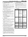
5. CHANGING THE FRYING OIL
The oil must be changed as soon as it becomes dark brown
with use. To do so, proceed as follows:
D Turn the mains switch (1) to 0. Allow the oil in the oil trough
to cool down fully.
D Open the door in the base unit.
D Attach the extension piece for draining the oil to the drain
cock.
D Place the collecting basin under the drain opening without
the strainer.
D Open the drain cock and drain all the oil carefully.
D Used frying oil must be regularly disposed of.
6. CLEANING
The appliance should be cooled before every cleaning
operation.
D Turn off the drain cock and pour boiling water with a degre-
asing agent (soda) into the oil trough (about 2“ (5 cm)
above the oil level mark).
D Allow to stand for 30 minutes.
D Clean the grid insert, baskets, strainer, cover and collecting
basin outside the appliance.
D Clean the oil troughs with a stiff brush (not a steel brush).
D Drain the water.
D The residues of the degreasing agent disintegrate the
frying fat. After cleaning rinse thoroughly with clean, luke-
warm water and rub dry with a clean cloth.
D Close the drain cock with the handle.
D Fill with clean oil.
D Never wash the control panel with water, just wipe it clean
with a dry cloth.
D Wash rust-resistant chrome nickel steel panels with hot
soapy water to which a fat-dissolving agent has been
added and rub them dry.
Note
D The appliance must not be sprayed with a water jet or
high-pressure cleaner.
D The floor directly in front of, near and behind the appliance
must be cleaned normally without a high-pressure cleaner.
D Never use steel wool, spatulas or ordinary steel wire
brushes for cleaning the surfaces, since the deposition of
steel particles can lead to rust formation. Stainless steel
wool can possibly be used, but only in the grinding
direction.
D Never use chloric products (bleaching dye, hydrogen
chloride etc.) for cleaning chrome nickel steel, even if they
are diluted.
D Never use corrosive substances for cleaning the floor
under the appliance (e.g. hydrochloric acid). Clean the
appliance with commercial cleaning agents.
7. SHUTTING DOWN
The following should be observed when shutting down for a
long period:
D Never store the fryer where the temperature can drop
below 32°F (0 C°).
D Do not leave the troughs full of water, since this prevents
the normal passivation of the steel and the surfaces are
thus less resistant to corrosion.
D Rub all chrome nickel steel surfaces with a cloth soaked in
vaseline oil, to lay down a thin protective coating.
D Air the installation site regularly.
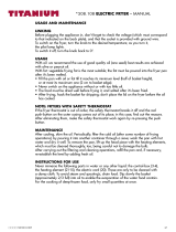
8. MALFUNCTION
Malfunction Possible cause Remedy
Fryer does not heat up. • The STB limiter has
tripped.
• Defective thermostat.
• The oil temperature
has exceeded 230°C.
• The capillary tube sen-
sor is damaged.
• The heating is opera-
ting in the trough wit-
hout oil.
• Oil level is too low.
• No power.
• Defective ON-OFF
switch.
- Contact the nearest
service station by
telephone.
- Inform After-Sales
Service.
- Inform After-Sales
Service.
- Inform After-Sales
Service.
Fill with oil.
- Top up with oil.
- Check fuses, plug, sok-
ket.
- Inform After-Sales
Service.
Fryer does not heat up but
lamps go on.
• Defective heating
element.
• Fryer 23 lt.:
If the control contactor
is faulty, the fryer only
has half power.
• Fryer 2x14 lt.:
The STB has triggered
(operating lamp is on.
Control lamp does not
light.)
- Inform After-Sales
Service.
- Inform After-Sales
Service.
- Inform After-Sales
Service.
Fryer overheats; the oil
smokes; the power is too
weak.
• Oil level too low. - Fill with oil up to the
max. mark.
Fryer does not heat up
quickly enough (12 minu-
tes instead of 6).
• One phase of the elec-
tric supply has no cur-
rent.
• Faulty heating element.
- Check fuses, plug, sok-
ket.
- Inform After-Sales
Service.
Fuses blow when swit-
ching on.
• Short-circuit in the
appliance.
- Inform After-Sales
Service.
Residual current circuit
breaker in fuse box swit-
ches off.
• Damp or poor insula-
tion in electric circuit.
- Inform After-Sales
Service.
Page is loading ...
Page is loading ...
Page is loading ...
Page is loading ...
Page is loading ...
Page is loading ...
Page is loading ...
Page is loading ...
-
 1
1
-
 2
2
-
 3
3
-
 4
4
-
 5
5
-
 6
6
-
 7
7
-
 8
8
-
 9
9
-
 10
10
-
 11
11
-
 12
12
-
 13
13
-
 14
14
-
 15
15
-
 16
16
-
 17
17
-
 18
18
-
 19
19


Ask a question and I''ll find the answer in the document
Finding information in a document is now easier with AI
in other languages
- français: Electrolux 584100 Manuel utilisateur
Related papers
-
Electrolux 9CHG584103 User manual
-
-
-
-
-
-
-
-
Electrolux 7PCSE1AU Operating instructions
-
Other documents
-
CONTINENTAL EDISON DF-62 User manual
-
Brandt FRI2202E User manual
-
Bartscher 162550 Operating instructions
-
 Titanium 508108 User manual
-
Bartscher 162913 Operating instructions
-
Bartscher 165530 Operating instructions
-
Atag FR3011A User manual
-
Vollrath Fryer, Cayenne®, Countertop, Standard-Duty User manual
-
-
