OM-129 647 Page 1
SECTION 1 − SAFETY PRECAUTIONS - READ BEFORE USING
rom _nd_11/98
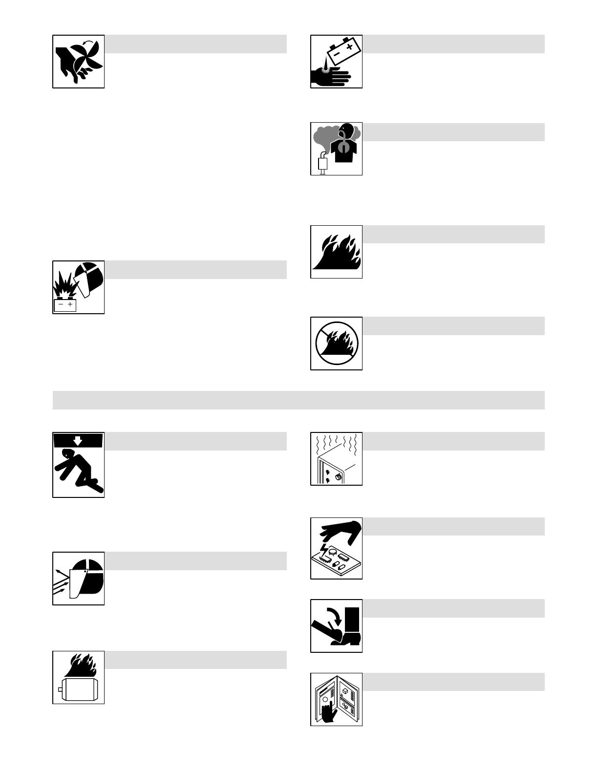
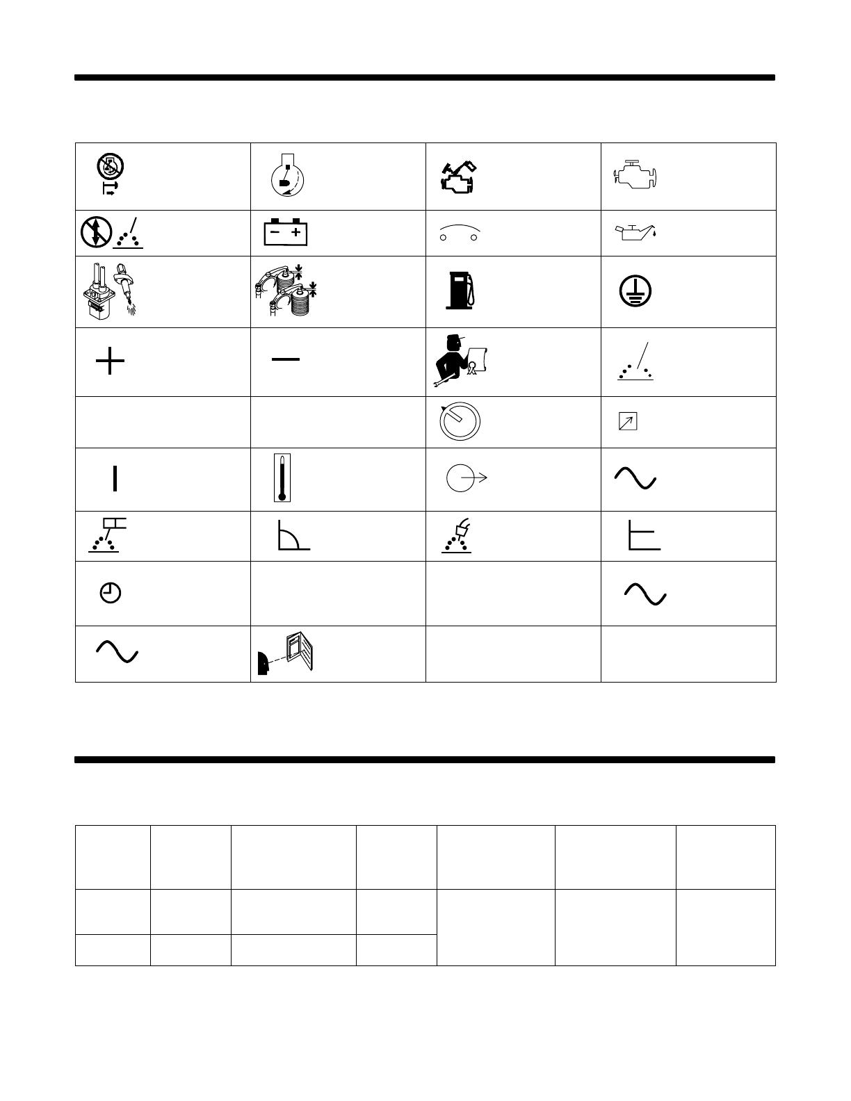
1-1. Symbol Usage
Means Warning! Watch Out! There are possible
hazards with this procedure! The possible hazards are
shown in the adjoining symbols.
Marks a special safety message.
Means “Note”; not safety related.
This group of symbols means Warning! Watch Out! possible
ELECTRIC SHOCK, MOVING PARTS, and HOT PARTS hazards.
Consult symbols and related instructions below for necessary
actions to avoid the hazards.
1-2. Arc Welding Hazards
The symbols shown below are used throughout this manual
to call attention to and identify possible hazards. When you
see the symbol, watch out, and follow the related instructions
to avoid the hazard. The safety information given below is
only a summary of the more complete safety information
found in the Safety Standards listed in Section 1-5. Read and
follow all Safety Standards.
Only qualified persons should install, operate, maintain, and
repair this unit.
During operation, keep everybody, especially children, away.
ELECTRIC SHOCK can kill.
Touching live electrical parts can cause fatal
shocks or severe burns. The electrode and work
circuit is electrically live whenever the output is on.
The input power circuit and machine internal
circuits are also live when power is on. In semiautomatic or
automatic wire welding, the wire, wire reel, drive roll housing, and all
metal parts touching the welding wire are electrically live. Incorrectly
installed or improperly grounded equipment is a hazard.
Do not touch live electrical parts.
Wear dry, hole-free insulating gloves and body protection.
Insulate yourself from work and ground using dry insulating mats
or covers big enough to prevent any physical contact with the
work or ground.
Do not use AC output in damp areas, if movement is confined, or if
there is a danger of falling.
Use AC output ONLY if required for the welding process.
If AC output is required, use remote output control if present on
unit.
Disconnect input power or stop engine before installing or
servicing this equipment. Lockout/tagout input power according
to OSHA 29 CFR 1910.147 (see Safety Standards).
Properly install and ground this equipment according to its
Owner’s Manual and national, state, and local codes.
Always verify the supply ground − check and be sure that input
power cord ground wire is properly connected to ground terminal
in disconnect box or that cord plug is connected to a properly
grounded receptacle outlet.
When making input connections, attach proper grounding
conductor first − double-check connections.
Frequently inspect input power cord for damage or bare wiring −
replace cord immediately if damaged − bare wiring can kill.
Turn off all equipment when not in use.
Do not use worn, damaged, undersized, or poorly spliced cables.
Do not drape cables over your body.
If earth grounding of the workpiece is required, ground it directly
with a separate cable.
Do not touch electrode if you are in contact with the work, ground,
or another electrode from a different machine.
Use only well-maintained equipment. Repair or replace damaged
parts at once. Maintain unit according to manual.
Wear a safety harness if working above floor level.
Keep all panels and covers securely in place.
Clamp work cable with good metal-to-metal contact to workpiece
or worktable as near the weld as practical.
Insulate work clamp when not connected to workpiece to prevent
contact with any metal object.
Do not connect more than one electrode or work cable to any
single weld output terminal.
SIGNIFICANT DC VOLTAGE exists after stopping
engine on inverters.
Stop engine on inverter and discharge input capacitors according
to instructions in Maintenance Section before touching any parts.
Arc rays from the welding process produce intense
visible and invisible (ultraviolet and infrared) rays
that can burn eyes and skin. Sparks fly off from the
weld.
ARC RAYS can burn eyes and skin.
Wear a welding helmet fitted with a proper shade of filter to protect
your face and eyes from arc rays and sparks when welding or
watching (see ANSI Z49.1 and Z87.1 listed in Safety Standards).
Wear approved safety glasses with side shields under your
helmet.
Use protective screens or barriers to protect others from flash and
glare; warn others not to watch the arc.
Wear protective clothing made from durable, flame-resistant
material (wool and leather) and foot protection.
Welding produces fumes and gases. Breathing
these fumes and gases can be hazardous to your
health.
FUMES AND GASES can be hazardous.
Keep your head out of the fumes. Do not breathe the fumes.
If inside, ventilate the area and/or use exhaust at the arc to
remove welding fumes and gases.
If ventilation is poor, use an approved air-supplied respirator.
Read the Material Safety Data Sheets (MSDSs) and the
manufacturer’s instructions for metals, consumables, coatings,
cleaners, and degreasers.
Work in a confined space only if it is well ventilated, or while
wearing an air-supplied respirator. Always have a trained watch-
person nearby. Welding fumes and gases can displace air and
lower the oxygen level causing injury or death. Be sure the
breathing air is safe.
Do not weld in locations near degreasing, cleaning, or spraying
operations. The heat and rays of the arc can react with vapors to
form highly toxic and irritating gases.
Do not weld on coated metals, such as galvanized, lead, or
cadmium plated steel, unless the coating is removed from the
weld area, the area is well ventilated, and if necessary, while
wearing an air-supplied respirator. The coatings and any metals
containing these elements can give off toxic fumes if welded.