Page is loading ...

COMSPHERE
3825
P
LUS
MODEM
USER’S GUIDE
Document No. 3825-A2-GB30-20
November 1996

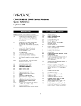
Your modem needs a serial cable to connect it to your computer. One end must have
a 25-pin plug, and the other end must have a socket that matches the modem port
on your computer.
This is a 25-pin
or a 9-pin
connector.
Quick Installation for the COMSPHERE 3825
Plus
Modem
Plug the serial cable
into your modem.
Plug the serial cable into the
serial port of your PC.
Plug your phone into the modem jack
marked PHONE.
Take one end of the line cord
(included with your modem) and
plug it into the modem jack
marked LINE. (See your User's
Guide for information about
leased-line connections.)
Take the other end of the line cable and
plug it into your telephone wall outlet.
Plug the small power
connector into the
modem jack marked
POWER.
Plug the transformer at the
other end of the power
cord into a 110 Vac power
outlet. Turn on your
modem and your PC.
B. Get your QuickLink II Fax software ready:
C. Get yourself ready!
A. Get your modem ready:
2. From the Microsoft
Windows Program Manager, select File Run, and then type
a:install (or b:install, if you are using drive B) at the command line. (Under DOS, type
at the C:\>prompt.) Press Enter.
3. Follow the instructions the install program displays on your screen. Let the Auto Detect
feature determine which COM port you are using.
You are now all set to explore a world of information and entertainment. Use QuickLink II Fax
to send and receive faxes, or to dial Bulletin Board Systems and friends. Subscribe to online
services like CompuServe, GEnie, and America Online. Connect with a few of the millions of
people with computers and fax machines.
If you have questions about your modem, refer to page A for contact information.
1. Insert the QuickLink II Fax disk into your disk drive.

COMSPHERE 3825Plus Modem
A November 1996 3825-A2-GB30-20
COMSPHERE
3825
Plus
Modem
User’s Guide
3825-A2-GB30-20
3rd
Edition (November 1996)
Changes and enhancements to the product and to the information herein will be documented and issued as a new release or a limited
revision of this manual.
The 3825Plus modem connects to the Public Switched Telephone Network (PSTN) using the Universal Service Order Code (USOC)
for Permissive mode, RJ11C. An RJ14C jack must be used to connect a two-line telephone to the modem. The Canadian equivalent to
RJ11C is CA11A and the Canadian equivalent to RJ14C is CA14A. For connection to an analog private line, an adapter cable should be
used to facilitate connection to a JM8 jack. The Canadian equivalent is CA40A.
FCC Registration number: (See label on modem)
Ringer Equivalence number (REN): (See label on modem)
Canadian Certification number: (See label on modem)
Canadian DOC Load number: (See label on modem)
Warranty, Sales, and Service Information
Contact your sales or service representative directly for any help needed. For additional information concerning warranty, sales,
service, repair, installation, documentation, or training, use one of the following methods:
• Via the Internet: Visit the Paradyne World Wide Web site at http://www.paradyne.com
• Via Telephone: Call our automated call system to receive current information via fax or to speak with a company representative.
— Within the U.S.A., call 1-800-870-2221
— International, call 813-530-2340
Trademarks
All products and services mentioned herein are the trademarks, service marks, registered trademarks or registered service marks of their
respective owners.
COPYRIGHT E 1996 Paradyne Corporation. All rights reserved.
This
publication is protected by federal copyright law
. No part of this publication may
be copied or distributed, transmitted, transcribed, stored in a retrieval system,
or
translated into any human or computer language in any form or by any means, electronic, mechanical, magnetic, manual or otherwise, or disclosed to third parties
without
the express written permission of Paradyne Corporation, 8545 126th A
venue North, P
.O. Box 2826, Largo, Florida 33779-2826.
Paradyne
Corporation makes no representation or warranties with respect to the contents hereof and specifically disclaims any implied warranties of
merchantability
or
fitness for a particular purpose. Further
, Paradyne Corporation reserves the right to revise this publication and to make changes from time to time in the contents
hereof
without obligation of Paradyne Corporation to notify any person of such revision or changes.
Printed on recycled paper

Safety Instructions
B3825-A2-GB30-20 November 1996
Important Safety Instructions
1. Read and follow all warning notices and instructions marked on the product or included in
the manual.
2. Slots and openings in the cabinet are provided for ventilation. To ensure reliable operation of the
product and to protect it from overheating, these slots and openings must not be blocked or covered.
3. Do not allow anything to rest on the power cord and do not locate the product where persons will
walk on the power cord.
4. Do not attempt to service this product yourself, as opening or removing covers may expose you to
dangerous high voltage points or other risks. Refer all servicing to qualified service personnel.
5. General purpose cables are provided with this product. Special cables, which may be required by the
regulatory inspection authority for the installation site, are the responsibility of the customer.
6. When installed in the final configuration, the product must comply with the applicable Safety
Standards and regulatory requirements of the country in which it is installed. If necessary, consult
with the appropriate regulatory agencies and inspection authorities to ensure compliance.
7. Input power to this product must be provided by one of the following: (1) a UL Listed, CSA
Certified power source with a Class 2 or Limited Power Source (LPS) output for use in North
America, or (2) a certified power source with a Safety Extra Low Voltage (SELV) output for use in
the country of installation.
In addition, if the equipment is to be used with telecommunications circuits, take the following
precautions:
— Never install telephone wiring during a lightning storm.
— Never install telephone jacks in wet locations unless the jack is specifically designed for wet
locations.
— Never touch uninsulated telephone wires or terminals unless the telephone line has been
disconnected at the network interface.
— Use caution when installing or modifying telephone lines.
— Avoid using a telephone (other than a cordless type) during an electrical storm.
— There may be a remote risk of electric shock from lightning.
— Do not use the telephone to report a gas leak in the vicinity of the leak.

COMSPHERE 3825Plus Modem
C November 1996 3825-A2-GB30-20
Notices
!
!
!
!

Safety Instructions
D3825-A2-GB30-20 November 1996
Government Requirements and Equipment Return
Certain governments require that instructions pertaining to modem connection to the public switched telephone network be included in
the installation and operation manual. Specific instructions are listed in the following sections.
United States
Notice To Users Of The Public Switched Telephone Network
1. This equipment complies with Part 68 of the FCC rules. On the equipment is a label that contains, among other information,
the FCC registration number and ringer equivalence number (REN) for this equipment. The label is located on the bottom of
your modem.
2. Page A of this manual contains the Universal Service Order Codes (USOC) associated with the services on which the
equipment is to be connected.
3. The Ringer Equivalence (REN) is used to determine the quantity of devices which may be connected to the telephone line.
Excessive RENs on the telephone line may result in the devices not ringing in response to an incoming call. In most, but not
all areas, the sum of the RENs should not exceed five (5.0). To be certain of the number of devices that may be connected to
the line, as determined by the total RENs, contact the telephone company to determine the maximum RENs for the calling
area.
4. If the modem causes harm to the telephone network, the telephone company will notify you in advance that temporary
discontinuance of service may be required. But if advance notice is not practical, the telephone company will notify the
customer as soon as possible. Also, you will be advised of your right to file a complaint with the FCC if you believe it is
necessary.
5. The telephone company may make changes in its facilities, equipment, operations, or procedures that could affect the
operation of the equipment. If this happens, the telephone company will provide advance notice in order for you to make the
necessary modifications in order to maintain uninterrupted service.
6. If you experience trouble with this equipment, please contact your sales or service representative (as appropriate) for repair or
warranty information. If the product needs to be returned to the company service center for repair, contact them directly for
return instructions using one of the following methods:
• Via the Internet: Visit the Paradyne World Wide Web site at http://www.paradyne.com
• Via Telephone: Call our automated call system to receive current information via fax or to speak with a company
representative.
— Within the U.S.A., call 1-800-870-2221
— International, call 813-530-2340
If the trouble is causing harm to the telephone network, the telephone company may request that you remove the equipment
from the network until the problem is resolved.
7. The user is not authorized to repair or modify the equipment.
8. This equipment cannot be used on public coin service provided by the telephone company. Connection to Party Line Service
is subject to state tariffs. (Contact the state public utility commission, public service commission or corporation commission
for information.)
9. The Telephone Consumer Protection Act of 1991 makes it unlawful for any person to use a computer or other electronic
device to send any message via a telephone fax machine unless such a message clearly contains, in a margin at the top or
bottom of each transmitted page, or on the first page of the transmission, the date and time it is sent, and an identification of
the business, or other entity, or other individual sending the message, and the telephone number of such business, or other
entity, or individual.
In order to program this information, follow the steps outlined in the manual supplied with your fax software.
10. An FCC compliant telephone cord with modular plugs may be provided with this equipment. This equipment is designed to
be connected to the telephone network or premises wiring using a compatible modular jack which is Part 68 compliant.

COMSPHERE 3825Plus Modem
E November 1996 3825-A2-GB30-20
Canada
Notice To The Users Of The Canadian Public Switched Telephone Network
The Canadian Department of Communications label identifies certified equipment. This certification means that the equipment meets
certain telecommunications network protective, operational and safety requirements. The Department does not guarantee the equipment
will operate to the user’s satisfaction.
Before installing this equipment, users should ensure that it is permissible to be connected to the facilities of the local
telecommunications company. The equipment must also be installed using an acceptable method of connection. In some cases, the
company’s inside wiring associated with a single line individual service may be extended by means of a certified connector assembly
(telephone extension cord). The customer should be aware that compliance with the above conditions may not prevent degradation of
service in some situations.
Repairs to certified equipment should be made by an authorized Canadian maintenance facility designated by the supplier. Any repairs
or alterations made by the user to this equipment, or equipment malfunctions, may give the telecommunications company cause to
request the user to disconnect the equipment.
Users should ensure for their own protection that the electrical ground connections of the power utility, telephone line and internal
metallic water pipe system, if present, are connected together. This precaution may be particularly important in rural areas.
The Load Number for this equipment is listed on a label on the modem. The Load Number (LN) assigned to each terminal device
denotes the percentage of the total load to be connected to a telephone loop which is used by the device to prevent overloading. The
termination on a loop may consist of any combination of devices subject only to the requirement that the total of the Load Numbers of
all devices does not exceed 100.
If your equipment is in need of repair, refer to the procedures in the Government Requirements and Equipment Return section.

Safety Instructions
F3825-A2-GB30-20 November 1996
United Kingdom
Ringer Equivalence Number
The Ringer Equivalence Number (REN) is a customer guide indicating approximately the maximum number of items of apparatus that
should be connected simultaneously to the telephone line. The sum of the RENs should not exceed four. This value includes any
BT-provided instrument which may be assumed to have a REN of 1 unless marked otherwise. The REN of this modem is 1.
Connection to Leased Lines
If any other apparatus, including cable or wiring, is connected between the apparatus and the point of connection to any speechband
circuit, then all that other apparatus shall comply with the following:
1. The overall transmission characteristics of all that other apparatus shall be such as to introduce no material effect upon the
electrical conditions presented to one another by the apparatus and the speechband circuit; and
2. All that other apparatus shall comprise only:
(i) apparatus approved for the purpose of connection between the apparatus and a speechband circuit; and
(ii) cable or wiring complying with a code of practice for the installation of equipment covered by this part of BS 6328 or
such other requirements as may be applicable.
This modem is suitable for connection to BT circuits with signalling at a nominal frequency of 2280 Hz and may be connected to
multipoint or point to point circuits. The apparatus does not require signalling or otherwise use the frequency range 0–200 Hz.
No d.c. interaction is intended between the modem and the telephone network.
This apparatus may be directly connected to a speechband circuit or connected to a relevant branch system for speechband circuits.
Connection to Supply Mains
IMPORTANT: The wires in the mains lead supplied with this equipment are coloured in accordance with the following code:
Blue — Neutral
Brown — Live
As the colours of the cores in the mains lead of this equipment may not correspond with the coloured markings identifying the
terminals in your plug, proceed as follows:
• The core which is coloured blue must be connected to the terminal which is marked with the colour N or coloured black.
• The core which is coloured brown must be connected to the terminal which is marked with the letter L or coloured red.
All European Countries
Safety Notice
For pluggable equipment, the mains socket outlet shall be installed near the equipment and be easily accessible.
Interconnection circuits between this modem and any other equipment should be such that the equipment continues to comply with the
requirements of EN41003 for TNV (Telephone Network Voltage) circuits and EN60950 for SELV (Safety Extra Low Voltage) circuits
after making connection between circuits.
The power supply must be properly connected and switched on before the modem will work correctly.

COMSPHERE 3825Plus Modem
G November 1996 3825-A2-GB30-20
Japan
Notices
This equipment is in the 2nd Class category (information equipment to
be used in a residential area or an adjacent area thereto) and conforms
to the standards set by the Voluntary Control Council for Interference by
Information Technology Equipment aimed at preventing radio
interference in such residential area.
When used near a radio or TV receiver, it may become the cause of
radio interference.
Read the instructions for correct handling.
Restrictions
Due to JATE (Japan Approvals Institute for Telecommunications Equipment) regulations, only 3 attempts to dial a number are
permitted in a 3-minute period. If a fourth attempt is made to dial the same number, the modem returns the ERROR return code. This
restriction applies to the number dialed from the command line or from a directory. An occurrence of the restriction is canceled when a
different number is dialed, or when 3 minutes have elapsed.

i3825-A2-GB30-20 November 1996
Table of Contents
Preface
Objectives
and Reader Assumptions
v. . . . . . . . . . . . . . . . . . . . . . . . .
How to Use This Manual
v. . . . . . . . . . . . . . . . . . . . . . . . . . . . . . . . . .
Related Documents
v. . . . . . . . . . . . . . . . . . . . . . . . . . . . . . . . . . . . . .
1. Introduction
Overview 1-1. . . . . . . . . . . . . . . . . . . . . . . . . . . . . . . . . . . . . . . . . . . . . .
Features 1-1. . . . . . . . . . . . . . . . . . . . . . . . . . . . . . . . . . . . . . . . . . . . . . .
3825Plus Modem Front Panel and Status Indicators 1-2. . . . . . . . . . . . .
2. 3825Plus Modem Installation
Overview 2-1. . . . . . . . . . . . . . . . . . . . . . . . . . . . . . . . . . . . . . . . . . . . . .
3825Plus Modem Package
2-1. . . . . . . . . . . . . . . . . . . . . . . . . . . . . . . . .
3825Plus Installation 2-2. . . . . . . . . . . . . . . . . . . . . . . . . . . . . . . . . . . . .
DTE Connection 2-3. . . . . . . . . . . . . . . . . . . . . . . . . . . . . . . . . . . . . . . .
Dial-Line Connection 2-3. . . . . . . . . . . . . . . . . . . . . . . . . . . . . . . . . . . . .
2-Wire Leased-Line Connection 2-3. . . . . . . . . . . . . . . . . . . . . . . . . . . .
T
elephone Connection
2-3. . . . . . . . . . . . . . . . . . . . . . . . . . . . . . . . . . . .
AC Power Transformer Connection 2-3. . . . . . . . . . . . . . . . . . . . . . . . .
Communications Software Installation 2-3. . . . . . . . . . . . . . . . . . . . . . .
Modem Power-Up 2-4. . . . . . . . . . . . . . . . . . . . . . . . . . . . . . . . . . . . . . .
Selecting Factory Configuration Options 2-4. . . . . . . . . . . . . . . . . . . . .
Recovering AT Commands
2-5. . . . . . . . . . . . . . . . . . . . . . . . . . . . . . . .
Initialization Strings 2-6. . . . . . . . . . . . . . . . . . . . . . . . . . . . . . . . . . . . . .
3. Fax Operation
Overview 3-1. . . . . . . . . . . . . . . . . . . . . . . . . . . . . . . . . . . . . . . . . . . . . .
Fax Operation 3-1. . . . . . . . . . . . . . . . . . . . . . . . . . . . . . . . . . . . . . . . . . .

COMSPHERE 3825Plus Modem
ii November 1996 3825-A2-GB30-20
4. AT Commands and S-Registers
Overview 4-1. . . . . . . . . . . . . . . . . . . . . . . . . . . . . . . . . . . . . . . . . . . . . .
Operating Modes
4-1. . . . . . . . . . . . . . . . . . . . . . . . . . . . . . . . . . . . . . . .
Command Guidelines
4-2. . . . . . . . . . . . . . . . . . . . . . . . . . . . . . . . . . . . .
AT Command List 4-2. . . . . . . . . . . . . . . . . . . . . . . . . . . . . . . . . . . . . . .
S-Register List 4-17. . . . . . . . . . . . . . . . . . . . . . . . . . . . . . . . . . . . . . . . . .
Security 4-27. . . . . . . . . . . . . . . . . . . . . . . . . . . . . . . . . . . . . . . . . . . . . . .
5. Remote Access
Overview 5-1. . . . . . . . . . . . . . . . . . . . . . . . . . . . . . . . . . . . . . . . . . . . . .
Remote Access
5-1. . . . . . . . . . . . . . . . . . . . . . . . . . . . . . . . . . . . . . . . . .
A. Result Codes
Overview A-1. . . . . . . . . . . . . . . . . . . . . . . . . . . . . . . . . . . . . . . . . . . . . .
B. Troubleshooting
Overview B-1. . . . . . . . . . . . . . . . . . . . . . . . . . . . . . . . . . . . . . . . . . . . . .
Automatic Firmware Download B-5. . . . . . . . . . . . . . . . . . . . . . . . . . . .
C. Technical Specifications
D. Pin Assignments
EIA-232-E
Pin Assignments
D-1. . . . . . . . . . . . . . . . . . . . . . . . . . . . . . .
JM8 to RJ1
1 Crossover Cable
D-2. . . . . . . . . . . . . . . . . . . . . . . . . . . . . .

T
able of Contents
iii3825-A2-GB30-20 November 1996
E. CCITT V.25bis Dialing Commands and Responses
Overview E-1. . . . . . . . . . . . . . . . . . . . . . . . . . . . . . . . . . . . . . . . . . . . . .
Call Request Commands
E-2. . . . . . . . . . . . . . . . . . . . . . . . . . . . . . . . . .
Call Response
E-2. . . . . . . . . . . . . . . . . . . . . . . . . . . . . . . . . . . . . . . . . . .
Call Answer Commands
E-3. . . . . . . . . . . . . . . . . . . . . . . . . . . . . . . . . .
Program Normal (PRN) E-3. . . . . . . . . . . . . . . . . . . . . . . . . . . . . . . . . . .
Request List of Stored Numbers (RLN) E-3. . . . . . . . . . . . . . . . . . . . . .
List Stored Number Response (LSN) E-3. . . . . . . . . . . . . . . . . . . . . . . .
Command Response
E-4. . . . . . . . . . . . . . . . . . . . . . . . . . . . . . . . . . . . . .
F. Country-Specific Configuration Options
Configuration Options by Country F-1. . . . . . . . . . . . . . . . . . . . . . . . . .
Glossary
Index

v3825-A2-GB30-20 November 1996
Preface
Objectives and Reader
Assumptions
This
manual describes how to install and operate the
3825Plus modem. It is intended for all users of the
3825Plus modem.
How to Use This Manual
Chapter 1 provides information about the 3825Plus
modem’s hardware and software features, including the
front panel and status indicators.
Chapter 2 provides instructions for installing the
modem, selecting factory configuration options,
recovering the ability to use A
T commands, and using
AT command initialization strings.
Chapter 3 provides general information about fax
modem operation.
Chapter 4 provides instructions for displaying and
changing AT commands and S-Registers. These
commands control all aspects of the modem’s operation,
including Security
, which is described in a separate
section of this chapter
.
Chapter 5 shows how to use the Diagnostic Control
Panel (DCP) of a COMSPHERE modem to access and
control a remote 3825Plus modem.
Appendix A lists result codes produced by the modem.
Appendix B provides instructions for performing
diagnostic tests when data communications problems
occur, and explains the Automatic Firmware Download
process.
Appendix C lists the technical specifications of the
3825Plus modem.
Appendix D provides EIA-232-E and JM8 to RJ11
crossover cable pin assignments.
Appendix E provides V.25bis dialing information.
Appendix F shows configuration options whose
validity or default values vary according to country code.
The Glossary provides a description of terms used
throughout this manual.
Related Documents
3980-A2-GB30 COMSPHERE 3800Plus
Modems, User
’
s Guide
6700-A2-GY31 COMSPHERE 6700 Series
Network Management System,
User’
s Guide
6800-A2-GE26 COMSPHERE 6800 Series
Network Management System,
User’
s/System Administrator
’s
Guide
Call your sales representative to order additional
product documentation.

1-13825-A2-GB30-20 November 1996
Introduction
Overview 1-1. . . . . . . . . . . . . . . . . . . . . . . . . . . . . . . . . . . . . . . . . . . . . . . . . . . . . . . . . . . . . . . . . . . . . . . . . .
Features 1-1. . . . . . . . . . . . . . . . . . . . . . . . . . . . . . . . . . . . . . . . . . . . . . . . . . . . . . . . . . . . . . . . . . . . . . . . . . .
3825Plus Modem Front Panel and Status Indicators 1-2. . . . . . . . . . . . . . . . . . . . . . . . . . . . . . . . . . . . . . . .
Status Indicators (LEDs) 1-2. . . . . . . . . . . . . . . . . . . . . . . . . . . . . . . . . . . . . . . . . . . . . . . . . . . . . . . . . . .
Overview
The 3825Plus modem is a member of the
COMSPHERE 3800 Series Modem product line. The
3825Plus is a high-speed dial modem that offers reliable
asynchronous and synchronous operation over dial- or
two-wire leased-line networks. The 3825Plus modem’s
software defineability allows you to add enhancements
and new features as they become available, with no
further investment in hardware, no on-site personnel, and
minimal downtime.
High-speed data transfer and reliable throughput at
data rates as high as 33,600 bps over dial lines is made
possible by employing the latest techniques in modem
modulations, and using CCITT V
.42bis/MNP Class 5 data
compression and CCITT V.42/MNP error correction. In
addition to fast line speeds, the modem can send data to
the DTE at speeds as high as 1
15,200 bps.
The modem’s compatibility with a number of dialing
methods and protocols, such as asynchronous
AT commands and CCITT V.25bis dialing, permits
the 3825Plus to be used in a variety of applications and
environments while also allowing control over modem
configuration, dialing, and diagnostics. The modem offers
two preset factory configurations containing the most
often used modem settings. These factory presets provide
quick configuration for any asynchronous or UNIX
hardware-based dial environment.
Features
The 3825Plus modem has a wide variety of features,
including:
• Dial-Line Modulations: Proprietary extensions of
V.34 (33,600 and 31,200 bps), ITU-T V.34 (up to
28,800 bps), V.32terbo (19,200 and 16,800 bps),
CCITT V.32bis (up to 14,400 bps), V.32 (up to
9600 bps), V.22bis (2400 bps), V.22 (1200 bps),
V.21 (300 bps), Bell 212A (1200 bps), and
Bell 103J (300 bps).
• Two-wire Leased-Line Modulations: Proprietary
extensions of V
.34 (33,600 and 31,200 bps),
ITU-T V.34 (up to 28,800), V.32terbo (19,200 and
16,800 bps), V.32bis (14,400, 12,000, 9600, 7200,
and 4800 bps), V.32 (9600 and 4800 bps), and
V.22bis (2400 bps).
•
Class 1 and Class 2 Group III Fax modulations:
CCITT V.17 (14,400, 12,000, 9600, 7200 bps),
V.29 (9600, 7200 bps) and V.27ter (4800,
2400 bps).
• Convenient migration to new or optional features
through software downloading.
• CCITT V
.42bis and MNP Class 5 data
compression.
• Virtual error-free data integrity with CCITT V.42
and MNP Levels 2–
4 error control.
• Asynchronous dial DTE data rates from
300 bps–115,200 bps.
• Enhanced Throughput Cellular (ETC), which
improves reliability and speed over cellular links.
• Compatibility with the industry de facto standard
A
T Command set.
1

COMSPHERE 3825Plus Modem
1-2 November 1996 3825-A2-GB30-20
• High-speed
transmission using asynchronous,
synchronous, or UNIX devices over full- or
half-duplex dial networks or 2-wire leased lines.
• Support as a remote (tributary) device by the
COMSPHERE 6700 or 6800 Series Network
Management System.
• Compatibility with COMSPHERE 3800Plus, 3800,
and 3900 Series modems’ Remote Access Mode,
which allows users to view the configuration
options of a 3825Plus modem from their front
panel LCD displays.
• Storage of up to 10 telephone numbers to directory
locations.
• Originate Security and three Answer Security
modes.
• Callback Security with telephone directory index or
telephone number.
• Two factory-defined configurations and two
user-defined configuration areas.
3825
Plus
Modem Front Panel
and Status Indicators
The front panel of the 3825Plus
modem is equipped
with 8 LEDs (status indicators) that monitor modem
activity (Figure 1-1).
Status Indicators (LEDs)
The 3825Plus’
s status indicators continuously provide
information on the modem’s operating condition.
Table 1-1 lists the label, color and functionality of each
status indicator
.
495-14694
EC/SQ HS/RI CD OH/APL RD SD TR MR/Pwr
3825
Plus
Figure 1-1. 3825
Plus
Front Panel

Introduction
1-33825-A2-GB30-20 November 1996
Table 1-1
3825
Plus
LEDs
Label
Color Indicates
EC/SQ green Error Control/Signal Quality
ON: The modem is in Error Control mode.
Off: The modem is not in Error Control mode.
Flashing; Predominantly ON: The modem is in Error Control mode and is receiving errors due
to poor VF line signal quality.
Flashing; Predominantly Off: The modem is not in Error Control mode and is receiving errors
due to poor VF line signal quality.
HS/RI green High Speed/Ring Indicate
ON: Modem is operating at the rate for which it is configured.
Off: Modem is operating at a lower rate than that for which it is configured.
Cycling ON and Off: The Ring Indicate signal is being sent to the DTE.
CD green Carrier Detect
ON: The modem has detected a valid modulation carrier signal and is capable of transferring
received data to the DTE.
OH/APL green Off-Hook/Analog Private Line
ON: The modem is off-hook and set for Dial.
Off: The modem is on-hook and set for Dial.
Slow Flashing: Modem is set for Leased (APL).
RD green Receive Data
ON: Received data is being transferred to the DTE.
SD green Send Data
ON: The modem is receiving data from the DTE to transmit.
TR green Terminal Ready
ON: The DTE has turned ON the DTR (Data Terminal Ready) signal or the modem is
configured to ignore DTR.
Off: The DTR signal is Off.
MR/Pwr green Modem Ready/Power
ON: Signifies that Power is ON if the modem is set for Dial and is on-hook. Signifies that
the EIA DSR (Data Set Ready) signal is ON if the modem is off-hook or set for Leased.
Off: Signifies that Power is Off if the modem is set for Dial and is on-hook. Signifies that the
EIA DSR signal is Off if the modem is off-hook or set for Leased.
Slow Flash: Modem is in download-only mode.
Fast Flash: Modem is in cloning mode.
NOTE: In Leased mode, Power is ON when the OH LED is flashing.

2-13825-A2-GB30-20 November 1996
3825
Plus
Modem Installation
Overview 2-1. . . . . . . . . . . . . . . . . . . . . . . . . . . . . . . . . . . . . . . . . . . . . . . . . . . . . . . . . . . . . . . . . . . . . . . . . .
3825Plus Modem Package 2-1. . . . . . . . . . . . . . . . . . . . . . . . . . . . . . . . . . . . . . . . . . . . . . . . . . . . . . . . . . . .
Customer-Supplied Equipment 2-1. . . . . . . . . . . . . . . . . . . . . . . . . . . . . . . . . . . . . . . . . . . . . . . . . . . . . .
3825Plus Installation 2-2. . . . . . . . . . . . . . . . . . . . . . . . . . . . . . . . . . . . . . . . . . . . . . . . . . . . . . . . . . . . . . . .
DTE Connection 2-3. . . . . . . . . . . . . . . . . . . . . . . . . . . . . . . . . . . . . . . . . . . . . . . . . . . . . . . . . . . . . . . . . . . .
Dial-Line Connection 2-3. . . . . . . . . . . . . . . . . . . . . . . . . . . . . . . . . . . . . . . . . . . . . . . . . . . . . . . . . . . . . . . .
2-Wire Leased-Line Connection 2-3. . . . . . . . . . . . . . . . . . . . . . . . . . . . . . . . . . . . . . . . . . . . . . . . . . . . . . . .
Telephone Connection 2-3. . . . . . . . . . . . . . . . . . . . . . . . . . . . . . . . . . . . . . . . . . . . . . . . . . . . . . . . . . . . . . .
AC Power Transformer Connection 2-3. . . . . . . . . . . . . . . . . . . . . . . . . . . . . . . . . . . . . . . . . . . . . . . . . . . . .
Communications Software Installation 2-3. . . . . . . . . . . . . . . . . . . . . . . . . . . . . . . . . . . . . . . . . . . . . . . . . . .
Modem Power-Up 2-4. . . . . . . . . . . . . . . . . . . . . . . . . . . . . . . . . . . . . . . . . . . . . . . . . . . . . . . . . . . . . . . . . . .
Selecting Factory Configuration Options 2-4. . . . . . . . . . . . . . . . . . . . . . . . . . . . . . . . . . . . . . . . . . . . . . . . .
Recovering AT Commands 2-5. . . . . . . . . . . . . . . . . . . . . . . . . . . . . . . . . . . . . . . . . . . . . . . . . . . . . . . . . . . .
Initialization Strings 2-6. . . . . . . . . . . . . . . . . . . . . . . . . . . . . . . . . . . . . . . . . . . . . . . . . . . . . . . . . . . . . . . . .
V.25bis Applications 2-6. . . . . . . . . . . . . . . . . . . . . . . . . . . . . . . . . . . . . . . . . . . . . . . . . . . . . . . . . . . . . .
Synchronous Leased-Line Applications 2-6. . . . . . . . . . . . . . . . . . . . . . . . . . . . . . . . . . . . . . . . . . . . . . .
AT&T Exclusive Dialing for DATAKIT Applications 2-6. . . . . . . . . . . . . . . . . . . . . . . . . . . . . . . . . . . .
Overview
This chapter describes how to connect both provided
and customer
-supplied cables to the modem. In addition,
it describes how to recover AT commands when the
modem is in Dumb mode and how to enter initialization
strings for unique applications.
3825
Plus
Modem Package
After opening the modem’
s package, check for damage
and verify that the following items are present:
• This user’
s guide
• 3825Plus modem
• Power transformer
• One 6-position, 4-wire modular cord
• Fax software and documentation
If any hardware components are damaged, notify your
sales representative. Return equipment using the
procedures described in the
Government Requir
ements
and Equipment Return section in the front of this book.
Customer-Supplied Equipment
The following customer
-supplied equipment is
required to complete a data communications system using
a 3825
Plus modem:
• A DTE (a computer or a terminal) with an available
RS-232-E serial port.
• A shielded RS-232-E cable with a male DB-25
connector at one end to attach to the modem.
• One of the following modular dial or leased
network interfaces:
— RJ1
1C or RJ14C for dial applications
— JM8 for 2-wire leased network interface
•
For leased-line applications, a JM8 to RJ1
1
crossover cable (see Appendix D).
2

COMSPHERE 3825Plus Modem
2-2 November 1996 3825-A2-GB30-20
3825
Plus
Installation
Before
installing your standalone modem, make sure
your installation site is clean and well-ventilated. Allow
space around the modem for installing cables and
telephone cords, and make sure the modem is located
within reach of the ac power outlet. The distance between
your modem and DTE (computer or terminal) should not
exceed 50 feet if DTE data rates exceed 19,200 bps.
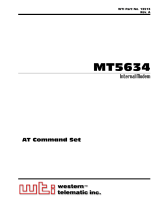
The rear panel of the 3825Plus modem (Figure 2-1)
has the following switches and connectors:
• An ON/Off power switch.
• A power receptacle for ac power transformer.
• A 25-pin DB-25 receptacle for your computer.
• A 6-pin modular jack for external telephone set use
only.
• A 6-pin modular jack for dial (PSTN) lines or
2-wire leased lines.
On/Off
Power
Computer
Phone
Line
Customer-Supplied
Cable
495-14695

3825Plus Modem Installation
2-33825-A2-GB30-20 November 1996
DTE Connection
Use the following procedure to connect the RS-232-E
cable from the modem to the DTE:
" Procedure
1.
Make sure the modem’
s rear panel power switch is
Off.
2. Connect the DB-25-P (male) connector on the cable
to the DB-25-S (female) connector labeled
COMPUTER (Figure 2-1) on the modem’s rear
panel. Use a small screwdriver to tighten the cable
to the modem.
3. Connect the DB-25-P connector on the cable to the
DB-25-S connector on the DTE. Use a small
screwdriver to tighten the cable to the DTE.
Dial-Line Connection
Use the following procedure to connect a 3825Plus to
the dial network interface.
" Procedure
1. Insert the 6-position, 4-conductor modular plug into
the jack labeled LINE, Figure 2-1.
2. Insert the other end of the modular cord into the
dial network interface.
2-Wire Leased-Line
Connection
Use the following procedure to connect a 3825Plus
modem to the 6-pin, center pair, leased-line network
interface. A description of the JM8 to RJ1
1C crossover
cable required can be found in Appendix D.
" Procedure
1. Insert the 6-position, 4-conductor modular plug into
the jack labeled LINE, Figure 2-1.
2. Insert the other end of the modular cord into the
leased-line network interface.
Telephone Connection
Use the following procedure to connect the modem to a
single-line or two-line telephone:
" Procedure
1. Insert the 6-position, 4-conductor modular plug into
the jack labeled PHONE.
2. Insert the other end of the modular cord into the
telephone.
AC Power Transformer
Connection
Use the following procedure to connect the modem to
an ac power outlet:
" Procedure
1.
Make sure the modem’
s power switch is in the Of
f
position.
2. Insert the power transformer’s cylindrical connector
into the modem’s rear panel ac power receptacle
labeled POWER (Figure 2-1).
3. Insert the power transformer into an ac power
outlet.
Communications Software
Installation
A personal computer commands and controls a dial
modem through communications software. This software,
which is installed on the PC, uses the A
T command set to
send instructions to the modem. A dumb asynchronous
terminal, however, does not require this software since it
can directly send A
T commands.
The 3825Plus
can be used with any major
communications software. Refer to your software’
s user
’s
guide for installation procedures. For an overview of how
to use A
T commands and a list of AT commands
supported by the 3825Plus, refer to Chapter 4, AT
Command Set and S-Registers
.

COMSPHERE 3825Plus Modem
2-4 November 1996 3825-A2-GB30-20
Modem Power-Up
Once your modem is properly connected to the DTE,
dial or leased lines, and ac outlet, press the modem’
s rear
panel power switch to the ON position. The modem
begins a power
-up self-test in which all front panel LEDs
momentarily light (note that this also occurs on a reset of
the modem), and the Power LED remains ON. The state
of other LEDs depends on your modem’s configuration.
See Table 1-1 in Chapter 1.
On initial power-up, the modem is in Command mode.
To verify that the modem is connected and functioning
properly, enter the following:
TYPE: AT
PRESS: Enter (Return)
The screen displays OK.
If the modem does not return OK, refer to
Appendix B,
Troubleshooting.
Selecting Factory
Configuration Options
After
the modem passes the power
-up self-test, it can
be configured for operation using one of the factory preset
configurations.
The purpose of preset configurations is to simplify the
customization your modem.
These factory preset templates contain the most
commonly used configuration options (straps) for
Asynchronous Dial, UNIX Dial, and Cellular
configurations. Your modem is shipped from the factory
with the Async Dial default configuration options stored
in memory. If UNIX Dial, Cellular (Mobile) or Cellular
(PSTN) is more appropriate for your configuration, then
you must change the factory setting as described as
follows.
NOTE
If you have already changed
certain configuration options, you
may have lost AT command
control. For example, operating in
Synchronous mode or disabling AT
commands results in an inability to
change configuration options. To
regain AT command control, refer
to the
Recovering AT Commands
section for these procedures.
To change a factory template, perform the following
steps (for more information on changing factory templates
using A
T commands, refer to Chapter 4, A
T Commands
and S-Registers
).
" Procedure
1.
Use the A
T&F&W command to load the
appropriate factory configuration to the appropriate
storage area. Enter the following:
TYPE: AT&Fy&Wn
Where: y is one of the following Factory
configurations:
0 for Async Dial
3 for UNIX Dial
5 for Cellular (Mobile)
6 for Cellular (PSTN)
and
Where: n is one of the following storage areas:
0 for Active (Saved)
1 for Customer 1
2 for Customer 2
These three configuration areas are
nonvolatile memory locations.
Active (Saved) contains the most
recently saved changes to any
configuration options. In the event of
power loss, the modem retrieves these
configuration options. Customer 1 and
Customer 2 are user
-defined
configuration storage areas.
2. PRESS: Enter (Return)
The selected factory configuration is saved.
/