Page is loading ...

CTB AND CTBR
CONVECTION OVEN
INSTALLATION - OPERATION - MAINTENANCE
BLODGETT OVEN COMPANY
www.blodgett.com
42 Allen Martin Drive, Essex Junction, Vermont 05452 USA Telephone: (802) 658-6600 Fax: (802)864-0183
PN 11361 Rev X (7/19)
© 2019 - G.S. Blodgett Corporation

Your Service Agency’s Address:
Model
Serial number
Oven installed by
Installation checked by

TABLE OF CONTENTS
INSTALLATION
Oven Description and Specications .................................................................... 2
Delivery and Location ........................................................................................... 3
Stand Assembly .................................................................................................... 4
Oven Assembly..................................................................................................... 6
Oven Assembly to Stand ................................................................................ 6
4” (10cm) Leg Attachment .............................................................................. 7
Caster Installation .......................................................................................... 7
Oven leveling ................................................................................................. 7
Adjustments Associated with Initial Installation ............................................. 7
Utility Connections - Standards and Codes .......................................................... 8
Electrical Connection ............................................................................................ 9
OPERATION
Safety Information .............................................................................................. 10
Solid State Manual ..............................................................................................11
Solid State Digital ............................................................................................... 12
Simple Touch Touchscreen Control .................................................................... 14
CH-Pro3 (Solid State Programmable Digital Control)......................................... 28
Blodgett IQ2™ Vision Control ............................................................................. 31
How Cook & Hold Works .................................................................................... 41
General Guidelines for Operating Personnel...................................................... 42
Suggested Times and Temperatures .................................................................. 43
MAINTENANCE
Cleaning and Preventative Maintenance ............................................................ 44
Troubleshooting Guide ....................................................................................... 35
IMPORTANT
WARNING: Improper installa-
tion, adjustment, alternation,
service or maintenance can
cause property damage, in-
jury or death. Read the instl-
lation, operation and mainte-
nance instructions thoroughly
before installing or servicing
this equipment.
FOR YOUR SAFETY
Do not store or use gasoline or
other ammable vapors or liq-
uids in the vicinity of this or any
other appliance.
The information contained in this
manual is important for the prop-
er installation, use, and mainte-
nance of this oven. Adherence
to these procedures and instruc-
tions will result in satisfactory
baking results and long, trou-
ble free service. Please read
this manual carefully and retain
it for future reference.
ERRORS: Descriptive, typo-
graphic or pictorial errors are
subject to correction. Speci-
cations are subject to change
without notice.

2
Installation
Oven Description and Specications
ELECTRICAL RATINGS- CTB & CTBR
VOLTAGE
KW
PHASE
MAX LOAD (AMPS) ELECTRICAL CONNECTION
AWG*
L1 L2 L3 N
60 HZ
208 5.6 1 27 — 27 — 8
5.6 3 24 12 15 — 10
6.8 1 33 — 33 — 6
6.8 3 20 18 19 — 10
8.0 1 35 — 35 — 6
8.0 3 22 20 21 — 10
220-240 5.6 1 24 — 24 — 8
5.6 3 21 11 14 — 10
6.8 1 28 — 28 — 6
6.8 3 18 16 17 — 10
8.0 1 32 — 32 — 6
8.0 3 20 18 19 — 10
50 HZ
220-240 5.6 1 24 — — 24 Size per local codes
6.8 1 28 — 28 —
8.0 1 35 — — 35
240/415 5.6 3 WYE 11 0 9 3 Size per local codes
6.8 3 WYE 11 9 9 —
8.0 3 WYE 13 11 11 2
230/400 5.6 3 WYE 11 0 10 1 Size per local codes
6.8 3 WYE 11 9 9 —
8.0 3 WYE 13 11 11 2
* Electric connection wiring is sized for 90ºC copper wire at 125% of rated input.
NOTE: Double units can have phase loads partially equalized by matching lines during hook-up. Otherwise, CTB-Double
or CTBR-Double load ratings are twice the above data.
Cooking in a convection oven diers from cooking in a
conventional deck or range oven since heated air is con-
stantly recirculated over the product by a fan in an en-
closed chamber. The moving air continually strips away
the layer of cool air surrounding the product, quickly al-
lowing the heat to penetrate. The result is a high qual-
ity product, cooked at a lower temperature in a shorter
amount of time.
Blodgett convection ovens represent the latest advance-
ment in energy eciency, reliability, and ease of opera-
tion. Heat normally lost, is recirculated within the cooking
chamber before being vented from the oven: resulting in
substantial reductions in energy consumption and en-
hanced oven performance.

3
Installation
Delivery and Location
DELIVERY AND INSPECTION
All Blodgett ovens are shipped in containers to prevent
damage. Upon delivery of your new oven:
• Inspect the shipping container for external damage.
Any evidence of damage should be noted on the
delivery receipt which must be signed by the driver.
• Uncrate the oven and check for internal damage.
Carriers will accept claims for concealed damage if
notied within fteen days of delivery and the ship-
ping container is retained for inspection.
The Blodgett Oven Company cannot assume responsibil-
ity for loss or damage suered in transit. The carrier as-
sumed full responsibility for delivery in good order when
the shipment was accepted. We are, however, prepared
to assist you if ling a claim is necessary.
OVEN LOCATION
The well planned and proper placement of your oven will
result in long term operator convenience and satisfactory
performance.
The following clearances must be maintained between
the oven and any combustible or non-combustible con-
struction.
CTB
• Oven body left side - 0” (0cm)
• Oven body back - 0” (0cm)
CTBR
• Oven body right side - 0” (0cm)
• Oven body back - 0” (0cm)
It is essential that an adequate air supply to the oven be
maintained to provide a sucient ow of combustion and
ventilation air.
• Area must be accessible for proper servicing.
• Keep the oven area free and clear of all combus-
tibles such as paper, cardboard, and ammable
liquids and solvents.
• To ensure proper operation, ventilation must not be
obstructed in any way. Tripping of the blower motor
thermal overload protective device is caused by ex-
cessive ambient temperature on the control side of
the oven resulting from insucient ventilation. This
condition must be corrected immediately to avoid
permanent damage to the oven.
Before making any utility connections to this oven, check
the rating plate to be sure the oven specications are
compatible with the electrical services supplied for the
oven.
1. The rating plate is attached to the underside of the
oven upper ledge above the control panel.
• Do not place strong sources of heat such as open
ame ranges, griddles, or charbroilers near the
oven. If such an instance exists, it is highly recom-
mended to purchase a heat shield, available from
Blodgett.
• Note that if temperatures are too high, a safety shut-
down may occur.
• Failure to comply may invalidate the oven warranty.

4
Installation
Stand Assembly
STAND OPTIONS
Small Stands Without Shelves
• The 5-3/4” (15cm) stand is used for a single oven,
when short legs are required for countertop use.
• The 7” (18cm) stand is used for a double stacked
oven, when the oven is to be located on the oor.
Stands With Shelves
• Three stands, 16” (40cm), 19” (48cm), and 24”
(61cm) are available for dierent installation require-
ments.
• The 33” (84cm) stand is used for a single oven when
counter space is limited.
Open Stands With Racks
• The 24” (61cm) or 33” (84cm) open stands are avail-
able with a rack support system located below the
oven.
STAND ASSEMBLY
Small Stands Without Shelves
1. Place stand frame upside down on a work surface.
2. Attach one leg to each of the corner stud bolts on the
bottom of the stand top.
3. Place a lock washer and nut on each stud, and tight-
en securely.
Stands With Shelves
1. Place stand frame upside down on a work surface.
2. Attach one leg to each of the corner stud bolts on the
bottom of the stand top.
3. Place a lock washer and nut on each bolt, and tight-
en. DO NOT tighten leg bolts completely.
4. Place the shelf between the legs so that the smooth
top surface is facing the top of the stand.
5. Align the shelf holes with the bolt holes found near
the bottom of each leg.
6. Insert a carriage bolt from the outside of the leg,
through the leg, and through the shelf corner bracket.
7. Place a lock washer and nut on each bolt, and tighten
securely.
8. Tighten the leg frame bolts.
Figure 1

5
Installation
Stand Assembly
Open Stands With Shelves and Racks
1. Place stand frame upside down on a work surface.
2. Attach one leg to each of the corner stud bolts on the
bottom of the stand top.
3. Place a lock washer and nut on each bolt, and tight-
en. DO NOT tighten leg bolts completely.
4. Attach the rack support angles to the stud bolts on the
bottom of the stand top with the nuts provided.
Each support angle has 2 clips on one end and 1 clip
on the other end. The two clips should be at the back
of the stand facing toward the center.
IMPORTANT - Be sure the support angles and
clips are located correctly for your oven congu-
ration as shown.
5. Position the bottom shelf between the legs so that the
smooth top surface is facing the top of the stand.
6. Align the shelf holes with the bolt holes found near
the bottom of each leg.
7. Insert a carriage bolt from the outside of the leg,
through the leg, and through the shelf corner bracket.
8. Place a lock washer and nut on each bolt, and tighten
securely.
9. Repeat Steps 5-8 for the top shelf.
NOTE: Be sure the slots in the top shelf are aligned
with the support angles.
10. Insert the top of the rack stops into the two back clips
on the angle supports as shown. Insert the bottom of
the rack stops into the slots in the top shelf as shown.
11. Insert the rack supports into the remaining four clips
on the angle supports as shown. Insert the bottom
of the rack supports into the slots in the top shelf as
shown.
12. Tighten all loose bolts.
Figure 2
CTB - Underside of Stand Top
Left
Support
Angle
Right
Support
Angle
Top Shelf
(rear)
Support Angle
Rack
Support
Attach Rack Supports
and Rack Stops
Clips
Rack Stop
Clips
CTBR - Underside of Stand Top
Clips
Left
Support
Angle
Right
Support
Angle
Proper Location of Support Angles
Rear of
Stand
Rear of
Stand

6
Installation
Oven Assembly
OVEN ASSEMBLY TO STAND
Single Section
1. Place the assembled stand in the location where the
oven is going to be used.
2. Remove the side control compartment cover and
open the front control panel of a single oven (or lower
section).
3. With a tool, punch out the knock-outs in the oven bot-
tom near each corner.
4. Set the oven on the stand. Center it to the frame.
5. Align the front, and rear bolt holes of the oven with the
bolt holes in the stand.
6. Insert a bolt and washer, from the top down through
each of the 2 holes.
7. Place a nut and washer on each of the 2 bolts, and
tighten securely.
8. Replace the oven’s side control compartment, and
close the front control panel.
NOTE: For single section ovens only. For double
stacked ovens this step will be completed
once the ovens are stacked.
Figure 3
Double Section
1. Assemble the lower section to the stand as described.
DO NOT replace the side control compartment or
close the front control panel.
2. With a tool, punch out the knock-outs in the oven top
of the lower oven.
3. Remove the side control compartment cover and
open the front control panel of the upper oven.
4. With a tool, punch out the knock-outs in the bottom of
the upper oven near each corner.
5. Set the upper oven on the lower oven.
6. Align the front, and rear bolt holes of the upper oven
with the bolt holes in the bottom oven.
7. Insert a bolt and washer, from the top down through
each of the 2 holes.
8. Place a nut and washer on each of the 2 bolts, and
tighten securely.
9. Replace the control compartment cover, and close
the front control panel on both of the ovens.
Figure 4

7
Installation
Oven Assembly
4” (10CM) LEG ATTACHMENT
1. Lay the oven on its side.
2. Screw one leg into each of the corner nuts.
Figure 5
CASTER INSTALLATION
NOTE: Casters are not supplied for the 4” (10cm) legs,
5-3/4” (15cm) or 7” (18cm) stands.
NOTE: Install the locking casters on the front of the oven.
Install the non-locking casters on the back of the
oven.
1. Insert the caster into the leg. Secure the caster to the
leg by tightening the locknut.
Figure 6
OVEN LEVELING
After assembly, the oven should be leveled and moved
to the operating location.
1. The oven can be leveled by adjusting the feet or cast-
ers located on the bottom of each leg.
ADJUSTMENTS ASSOCIATED WITH INITIAL INSTAL-
LATION
Each oven, and its component parts, have been thor-
oughly tested and inspected prior to shipment. However,
it is often necessary to further test or adjust the oven as
part of a normal and proper installation. These adjust-
ments are the responsibility of the installer, or dealer.
Since these adjustments are not considered defects in
material or workmanship, they are not covered by the
Original Equipment Warranty. They include, but are not
limited to:
• calibration of the thermostat
• adjustment of the doors
• leveling
• tightening of fasteners.
No installation should be considered complete without
proper inspection, and if necessary, adjustment by quali-
ed installation or service personnel.

8
Installation
Utility Connections - Standards and Codes
THE INSTALLATION INSTRUCTIONS CONTAINED
HEREIN ARE FOR THE USE OF QUALIFIED INSTAL-
LATION AND SERVICE PERSONNEL ONLY. INSTAL-
LATION OR SERVICE BY OTHER THAN QUALIFIED
PERSONNEL MAY RESULT IN DAMAGE TO THE OVEN
AND/OR INJURY TO THE OPERATOR.
Qualied installation personnel are individuals, a rm,
a corporation, or a company which either in person or
through a representative are engaged in, and responsible
for:
• the installation of electrical wiring from the electric
meter, main control box or service outlet to the elec-
tric appliance.
• Qualied installation personnel must be experienced
in such work, familiar with all precautions required,
and have complied with all requirements of state or
local authorities having jurisdiction.
U.S. and Canadian installations
All ovens, when installed, must be electrically grounded
in accordance with local codes, or in the absence of lo-
cal codes, with the National Electrical Code, ANSI/NFPA
70-Latest Edition and/or Canadian National Electric Code
C22.2 as applicable.
The ventilation of this oven should be in accordance with
local codes. In the absence of local codes, refer to the
National ventilation code titled, “Standard for the Installa-
tion of Equipment for the Removal of Smoke and Grease
Laden Vapors from Commercial Cooking Equipment”,
NFPA-96-Latest Edition.
General export installations
Installation must conform with Local and National instal-
lation standards. Local installation codes and/or require-
ments may vary. If you have any questions regarding the
proper installation and/or operation of your Blodgett oven,
please contact your local distributor. If you do not have a
local distributor, please call the Blodgett Oven Company
at 0011-802-658-6600.

9
Installation
Electrical Connection
Wiring diagrams are located in the control compartment
area.
Ovens are supplied for operation in several voltage choic-
es, single or three phase grounded circuits.
The electric motor, indicator lights and related switches
are interconnected through the one power source sup-
plied to the oven.
1. The supply conduit enters through the rear of the
oven and electrical block secured to the perforated
panel at the back of the control compartment.
The Blodgett Oven Company cannot assume responsibil-
ity for loss or damage suere

10
Operation
Safety Information
The information contained in this section is provided for
the use of qualied operating personnel. Qualied operat-
ing personnel are those who have carefully read the in-
formation contained in this manual, are familiar with the
functions of the oven and/or have had previous experi-
ence with the operation of the equipment described. Ad-
herence to the procedures recommended herein will as-
sure the achievement of optimum performance and long,
trouble-free service.
Please take the time to read the following safety and op-
erating instructions. They are the key to the successful
operation of your Blodgett oven.
SAFETY TIPS
For your safety read before operating
General safety tips:
• If the oven needs to be moved for any reason, the
supply cord must disconnected from the unit before
removing the restraint cable. Reconnect the restraint
after the oven has been returned to its original loca-
tion.
• DO NOT remove the control panel cover unless the
oven is unplugged.

11
Operation
Solid State Manual
COMPONENT DESCRIPTION
1. SELECTOR SWITCH - controls power to the oven
and selects Cool Down mode.
2. OVEN READY LIGHT - when lit, indicates heater
operation. When the light goes out, the oven has
reached operating temperature.
3. SOLID STATE THERMOSTAT - allows either 8 pre-
set temperatures to be selected in accordance with
customer requirements, or an innite selection of
temperatures from 200-500ºF (95-260ºC).
HEATING
THERMOSTAT
8 Setpoint Temperature
(275, 300, 325, 350,
375, 400, 425, 450ºF)
Customer specic
settings are available.
Figure 7
4. COOK TIMER - used to time the length of the cook-
ing operation. When the set time expires an alarm
sounds.
CONTROL OPERATION
1. Turn the SELECTOR SWITCH (1) to OVEN ON.
2. Set the COOK THERMOSTAT (3) to the desired tem-
perature.
3. Preheat the oven until the OVEN READY (2) light
goes out, indicating the oven has reached operating
temperature.
4. Load product into the oven. Set the COOK TIMER (4)
to the desired time.
5. When the buzzer sounds, remove the product from
the oven. Turn the timer to OFF to silence the alarm.
6. Turn the SELECTOR SWITCH (1) to OVEN OFF.
COOL
DOWN
OVEN OFF
DISCONNECT FROM THE SOURCE OF
SUPPLY BEFORE SERVICING
www.blodgett.com
CIRCUIT
BREAKER
HIGH
FAN
LOW FAN
TIMER
HEATING
THERMOSTAT
1
2
3
4
Figure 8

12
Operation
Solid State Digital
Solid State
1
2
3
8
7
10
4
5
6
9
11
Figure 9
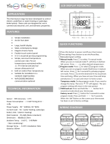
COMPONENT DESCRIPTION
1. SELECTOR SWITCH - turns power to the oven on
or o. Allows selection of Cook or Cool Down modes
and fan speed (if applicable).
2. DISPLAY - displays time, temperature, or other infor-
mation related to oven function.
3. HEAT LAMP - lights when heater is on.
4. PULSE LAMP - lights when Pulsed Fan Mode is
turned on.
5. HOLD LAMP - lights when Hold Mode is turned on.
6. DIAL - used to enter set points in display.
7. START/STOP KEY - starts or stops the timer.
8. TIME KEY - used to show time in the display.
9. TEMP KEY - used to show set temperature in the dis-
play.
NOTE: Actual temperature is shown while the TEMP
key is held down.
10. HOLD KEY - turns Hold Mode on or o.
11. PULSE KEY - turns Pulse Mode on or o.
PROGRAMMING
To set the cook temperature:
1. Press the TEMP (9) key.
2. Rotate the dial (6) to enter the cook temperature.
To set the cook time:
1. Press the TIME (8) key.
2. Rotate the dial (6) to enter the cook time.
NOTE: Time is entered in hours : minutes or minutes
: seconds.
To set the hold time:
1. Press the HOLD key (10) to turn hold mode on.
NOTE: HOLD light is on.
2. Rotate the dial (6) to enter the hold temperature.
3. Press the START/STOP key (7)
To set the pulse time:
1. Press the PULSE KEY (11) to turn pulse mode on.
NOTE: Pulse light is on.
2. Rotate the DIAL (6) to enter the pulse time. Pulse
time is a portion of the pre-set cook time.

13
Operation
Solid State Digital
OPERATION
Cook
1. Turn the SELECTOR SWITCH (1) to the desired posi-
tion.
2. Enter the cook time and temperature.
3. Load product into the oven.
NOTE: The display reads LOAD when the oven is
near set temperature.
4. Push the START/STOP key (7). The timer begins to
count down.
5. When the cook timer reaches 00:00 the buzzer
sounds and the display reads DONE.
6. Press the START/STOP key (7) to silence the buzzer.
7. Remove the product.
Cook with Hold
NOTE: The HOLD light is on when hold mode is on and
o when hold mode is o.
1. Turn the SELECTOR SWITCH (1) to the desired posi-
tion.
2. Enter the cook time and temperature.
3. Press the HOLD key (10). Enter the hold temperature.
4. Load product into the oven.
NOTE: The display reads LOAD when the oven is
near set temperature.
5. Push the START/STOP key (7). The timer begins to
count down.
6. When the cook timer reaches 00:00 the buzzer sounds
and the display reads DONE. The buzzer turns o af-
ter a few seconds. The display reads HOLD until the
oven reaches the hold temperature. Then the timer
begins to count up.
7. Push the START/STOP key (7) to stop the timer.
8. Remove the product.
9. Push the HOLD key (10) to turn o hold mode.
COOK WITH PULSE
NOTE: The PULSE light is on when pulse mode is on and
o when pulse mode is o.
1. Turn the SELECTOR SWITCH (1) to the desired posi-
tion.
2. Enter the cook time and temperature.
3. Press the PULSE KEY (11). Enter the pulse time.
NOTE: Pulse time is a portion of the cook time and
does not increase the previously entered
cook time.
4. Load product into the oven.
NOTE: The display reads LOAD when the oven is
near the set temperature.
5. Push the START/STOP KEY (9). The timer begins to
count down the cook time. The oven remains in pulse
mode for the set pulse time. When the set time ex-
pires, the unit automatically switches to cook mode
and continues counting down.
6. When the cook timer reaches 00:00 the buzzer
sounds and the display reads DONE.
7. Push the START/STOP KEY (9) to turn the buzzer o.
8. Remove the product.

14
Operation
Simple Touch Control
COMPONENT DESCRIPTION
1. TOUCHSCREEN - Interactive display for oven func-
tioning and/or programming.
2. USB Port - Use to transfer recipes and data to/from
the control.
3. HEAT CUTOFF - Used to turn heat source o.
4. CIRCUIT BREAKER – Provides circuit protection for
the oven controls. DO NOT use as a power switch.
5. CONTROL KNOB - Used to change values for time,
temperature, humidity, etc.
Figure 10
1
5
2
4
3

15
Operation
MANUAL MODE COOKING
1. Press POWER to turn on the oven.
2. Press MANUAL to proceed to the manual cook
screen.
Power
Figure 11
Simple Touch Control

16
Operation
Simple Touch Control
MANUAL COOK SCREEN
Actual Temp – Press thermometer to display the actual
cavity temperature.
Temperature Bar - Press the TEMPERTURE BAR and
use the control dial to set the desired oven temperature.
For temperature ranges from minimum to 215°F, the
temperature may be set in 1° increments as the knob is
turned.
For temperature above 215°F, the temperature may be
set in 5° increments.
Press the check mark to save the selection. Press the X
to cancel editing without altering current set point value.
Cook Timer - Press the TIMER STATUS BAR and enter
the desired cook time using the control dial.
Times greater than 1 hour can be set in 5 minute incre-
ments. Times less than 1 hour can be set in 5 second
increments.
Press the check mark to save the selection. Press the X
to cancel editing without altering current set point value.
Add a Minute - Press +1 MIN to add 1 minute of time at
any point during the cook cycle.
Light Activation - Press the LIGHT icon turn the cavity
lights on. The icon will change when activated. The lights
will remain on until the icon is pressed again by the user
OR the timeout period is reached. The default timeout pe-
riod is 5 minutes.
Fan Speed Bar - Press the FAN SPEED BAR to cycle
through the available fan speeds.
Advanced Functions – Press the ADV. FUN icon to ac-
cess the Fan Pulse, Fan Delay and Cook and Hold func-
tions.
Figure 12
Back
Actual
Temperature
Fan
Timer
Advanced
Functions
Start Timer
Stop Timer
Add a Minute
Light
Temperature Bar
Fan Speed Bar
Timer Status Bar

17
Operation
Simple Touch Control
TO OPERATE TIMER
1. Press PLAY to initiate timer. The timer counts down,.
The play button changes to pause.
Press the PAUSE button to stop the timer at current
value. The pause button changes back to play. Press
play to resume timer.
Presst the STOP key to clear the timer.
The +1 MIN key may be selected at any time to add
an additional minute to the current timer.
Timer Status Bar
The color of the timer bar represents a percentage of
original set time.
• GREEN: 50-100% of the time remains
• ORANGE: 25-49% of the time remains
• RED: 0-24% is indicated by Red
2. When the timer reaches zero, an audible alarm is trig-
gered.
NOTE: The timer stops when the door is opened and
resumes when the door is closed.
LIGHT ACTIVATION
Press the LIGHT key to turn on the cavity lights. The icon
turns yellow when activated. The key/relay will remain ac-
tive until pressed again OR the 5 minute default timeout
period is reached.
Play
Pause
Stop
Add a minute
Figure 13
Figure 14

18
Operation
Simple Touch Control
ADVANCED FUNCTIONS
Cook & Hold
The intent of Cook & Hold is to keep the product at a food
safe temperature while not overcooking. Once the cook
cycle is complete, the oven autmatically switches to the
hold time and temperature.
1. From the MANUAL COOK SCREEN, press the ADV.
FUN icon.
2. Press the COOK & HOLD key. Four settings bars ap-
pear: cook temp, cook time, hold temp and hold time.
3. Use the keypad to enter desired cook and hold time
and temperature settings.
4. Press the BACK key to return to the manual cook
screen.
• The C & H icon will replace the timer icon.
• The timer bar will show the cumulative time of
the cook and hold. The cook time will be shad-
ed.
• If the current set point diers from the Cook &
Hold set point, it will change upon returning to
the manual operation screen.
• Press play to initiate Cook & Hold.
5. When the recipe is complete, the oven will maintain
the Hold Temp until a new set temperature has been
dened.
Figure 15
/