Page is loading ...

INSTRUCTION MANUAL
System Controller
VSP-9000
About this manual
• Before installing and using this unit, please read this manual carefully. Be sure to keep it handy for
later reference.
• This manual gives basic connections and operating instructions.

English
1 Introduction
Table of Contents
Precautions (For UL) ...................................2
Safety Cautions............................................3
Major Characteristics..................................8
Accessories..................................................8
Part Names...................................................9
Menu Display..............................................11
System Information ...................................12
Sample System Connection .....................13
Connection and Communication
Setup 1 (VIDEO).........................................15
Connection and Communication
Setup 2 (VIDEO).........................................18
Connection and Communication
Setup 3 (VIDEO/TELEMETRY A)...............21
Connection and Communication
Setup 4 (VIDEO/TELEMETRY B)...............24
Connection and Communication
Setup 5 (VIDEO/TELEMETRY A/B) ...........27
Communication Lines and
Number of Connected Units .....................30
Hard Disk Digital Recorder (DVR)
Operation....................................................32
Multiplexer (MUX) operation .....................36
Dome Camera/Zoom Camera Operation..38
System Setup Overview............................41
Language Selection...................................42
Communication Setup...............................43
b Select a communication item
(COMMUNICATIONS)...................................... 43
b Unit Address Setup...........................................44
Control Setup.............................................47
b Select a Control Item
(ACCEPTED VALUES).....................................47
Password Setup (PASSWORD) ................50
b AT SWITCHING ON (Power ON password)..... 51
Setup (CONFIGURATION).........................52
b Initialize (RESTORE BASIS VALUES)............. 53
b Buzzer and menu display setup
(BUZZER/DISPLAY) ........................................ 53
b Joystick Setup (JOYSTICK) ............................. 54
b Touch screen adjustment
(TOUCH SCREEN SETTING).......................... 55
b Touch Screen Initialization and Reset.............. 56
b Touch screen test (TOUCH TEST) .................. 57
Software Configuration.............................59
b Operating Environment .................................... 59
Connection and Software Installation .....60
b Install the Software........................................... 60
b Making Connections......................................... 60
System Setup (Setup) ...............................61
A General (General Settings) .............................. 62
B Cameras (Camera communication setup)........ 64
C Monitor/Local Mux
(Valid/Invalid setup for hard disk digital recorder
with multiplexer) ............................................... 66
D Enabling (stopping or starting settings) ............ 67
Language Setup (Language) ....................68
b Creating Two Different English Tabs................ 69
Graphics Environment Setup (Maps) ......71
b Display Telephone Number on
Opening Screen ............................................... 72
b Map Screen Explanation .................................. 73
b Sample Equipment Allocation .......................... 76
b Protocol Chart (Autopan).................................. 79
b Protocol Chart (Patrol)...................................... 80
b Changing the Opening screen to “SANYO”...... 81
b Create a map using the graphics tool
and display on opening screen......................... 82
b Basic Graphics ................................................. 84
Specifications ............................................85
b Outer Dimensions (Units: mm) ......................... 85
Appendix ....................................................86
b Communications Chart..................................... 86
b Message Chart ................................................. 88
b Special Code Chart .......................................... 89
Introduction
Preparation
Operation
System Setup
Software
Others

English
Introduction 2
Precautions (For UL)
CAUTION:
Changes or modifications not
expressly approved by the manufacturer may
void the user's authority to operate this
equipment.
This equipment has been tested and found to
comply with the limits for a Class B digital
device, pursuant to part 15 of the FCC Rules.
These limits are designed to provide
reasonable protection against harmful
interference in a residential installation. This
equipment generated, uses and can radiate
radio frequency energy and, if not installed
and used in accordance with the instructions,
may cause harmful interference to radio
communications. However, there is no
guarantee that interference will not occur in a
particular installation. If this equipment does
cause harmful interference radio or television
reception, which can be determined by turning
the equipment off and on, the user is
encouraged to try to correct the interference
by one or more of the following measures:
• Reorient or relocate the receiving antenna.
• Increase the separation between the
equipment and receiver.
• Connect the equipment into an outlet on a
circuit different from that to which the
receiver is connected.
• Consult the dealer or an experienced radio/
TV technician for help.
For the customers in Canada
SERVICE
This unit is a precision instruments and if
treated with care, will provide years of
satisfactory performance. However, in the
event of a problem, the owner is advised not
to attempt to make repairs or open the
cabinet. Servicing should always be referred
to your dealer or Sanyo Authorized Service
Center.
CAUTION
RISK OF ELECTRIC SHOCK
DO NOT OPEN
CAUTION:
TO REDUCE THE RISK OF
ELECTRIC SHOCK, DO NOT REMOVE
COVER (OR BACK).
NO USER-SERVICEABLE PARTS INSIDE.
REFER SERVICING TO QUALIFIED
SERVICE PERSONNEL.
WARNING:
To reduce the risk of fire or
electric shock, do not expose this appliance
to rain or moisture.
The lightning flash with arrowhead
symbol, within an equilateral
triangle, is intended to alert the
user to the presence of
uninsulated “dangerous voltage”
within the product's enclosure that
may be of sufficient magnitude to
constitute a risk of electric shock
to persons.
The exclamation point within an
equilateral triangle is intended to
alert the user to the presence of
important operating and
maintenance (servicing)
instructions in the literature
accompanying the product.
This class B digital apparatus complies
with Canadian ICES-003.

English
3 Introduction
Safety Cautions
Main Unit
WARNING
b
bb
b Never use when unit emits smoke,
unusual noises, or unusual smells.
Using under these abnormal conditions
can cause fires and electric shock.
Immediately unplug the AC adapter power
plug from the outlet, confirm that the
smoke stops, and then request repairs
from the installer or the purchasing source.
Never attempt to repair the unit on your
own, as this is dangerous.
b
bb
b Never disassemble or modify
• Touching the internal parts is
dangerous, and can cause fires and
electric shock.
• Request internal inspection, adjustment,
and repairs from the installer or the
location of purchase.
b
bb
b Never get unit wet
• This unit is not waterproof or dustproof.
Do not install where exposed to rain,
excessive humidity, or excessive dust.
This can cause fires and electric shock.
Do not install in a bath or shower room.
• In the event that water enters the unit
interior, turn OFF power to the unit,
unplug the AC adapter power plug from
the outlet, and contact the installer or
location of purchase. Continued use can
cause fires, electric shock, and unit
breakdowns.
b
bb
b Do not use during thunderstorms
Do not use this during thunderstorms.
In particular, never touch the AC adapter
or connection cables. This can cause
electric shock.
b
bb
b Do not install in unstable location
• The unit may fall or topple, causing
injuries or unit breakdowns.
• In the event that the unit is dropped or
the cabinet is broken, turn OFF power to
the unit, unplug the AC adapter power
plug from the outlet, and contact the
installer or location of purchase.
Continued use can cause fires or
electric shock.
b
bb
b Do not use in locations with explosion
risk
Do not use in locations where flammable
gas or explosive gas may exist in the
atmosphere. This can cause ignition and
explosion.
WARNING
Never put menu display liquid crystal in
your mouth
If the menu display breaks and the liquid
crystal inside has leaked, be careful never
to put it in your mouth. This could cause
poisoning. In the event that it contacts your
mouth or eyes, wash immediately with
water and consult a physician. If it contacts
your hands or clothing, wipe it off with
alcohol etc., and wash it away with water.

English
Introduction 4
Safety Cautions
CAUTION
b
bb
b Transport with care
Unplug the AC adapter power plug from
the outlet, confirm that connection cables
are disconnected, and transport carefully
to avoid dropping the unit or subjecting it to
severe shock.
b
bb
b Cautions for care or long-term disuse
Unplug the AC adapter power plug from
the outlet. Caring for the unit with the AC
adapter connected can cause electric
shock.
b
bb
b Cleaning the interior
For cleaning the interior, consult the
installer or the location of purchase. When
dust has accumulated inside the unit over
time without cleaning, this can cause fires
or unit breakdowns.
b
bb
b Installation location
This unit is comprised of precision
electronic parts. Never install in the
locations described below, as this can
cause operation errors and unit
breakdowns.
• In direct sunlight
• In extreme humidity or where humidity
fluctuates wildly
• Where water could be splashed
• Near heating/cooling equipment or
humidifiers.
• Where cold air from air conditioners
contact the unit directly
• Where dust is extreme
• Near a spark source
• Near magnetic objects
• Near explosive materials
• Where subject to vibration
Provided AC Adapter
DANGER
b
bb
b Only use with 100 to 240V power source
voltage.
This can cause fires and electric shock.
b
bb
b Never disassemble or modify
• Touching the internal parts is
dangerous, and can cause fires and
electric shock.
• Never use as a DC power source unit.
b
bb
b Never get unit wet
• Never submerge in water or get unit wet.
This can cause fires and electric shock.
• Do not use in a bath or shower room.
• In the event that water enters the unit
interior, unplug the power plug from the
outlet, and contact the installer or
location of purchase. Continued use can
cause fires, electric shock, and unit
breakdowns.
DC plug
Power cord
Power plug
AC adapter

English
5 Introduction
Safety Cautions
(Continued)
Provided AC Adapter
WARNING
b
bb
b Use only the provided AC adapter
Use the provided AC adapter. Using a
different AC adapter can cause fires or
electric shock, due to differences in power
cord current capacity.
b
bb
b Never touch the AC adapter with wet
hands
This can cause electric shock.
b
bb
b Power plug
Never use while abnormality is not
corrected.
The following situations can cause fires or
electric shock.
• Never allow dust to accumulate on
power plug or in outlet insertion holes.
Dust and dirt on either contact portion
can cause an electric short or
overheating. Wipe off with a dry cloth.
• When using an outlet where humidity is
high or condensation forms easily, or an
outlet in a kitchen or dusty environment,
unplug the power plug regularly and
wipe off the dust and dirt adhering to the
plug.
• Never pull the power cord to unplug the
power plug.
Always hold the power plug when
unplugging.
• Never leave the power plug plugged into
the outlet while the DC plug is
disconnected from the power source
input terminal on this unit. This can
cause electric shock when touching with
wet hands, or when an infant places the
power plug in his/her mouth.
• Never use an outlet if the power plug is
fully seated but is still loose in the outlet.
This can cause fires due to overheating.
• Never use the power plug when it is
damaged. When the plug has poor
contact, consult the installer or the
location of purchase.
b
bb
b Power cord
Never bundle up the power cord during
use. This can cause overheating, fires and
electric shock.
b
bb
b When using an extension cord
Be careful that the total power
consumption of the connected equipment
does not exceed the rated power of the
extension cord.
Exceeding the rated power can cause
fires.

English
Introduction 6
Safety Cautions
CAUTION
b
bb
b Do not connect to other equipment
The provided AC adapter is exclusively for
this unit. Connecting to other equipment
can cause fires or electric shock.
b
bb
b Power cord
Damaging the power cord in the following
manner can cause fires or electric shock.
When the power cord is damaged, consult
the installer or the location of purchase.
• Never place a heavy object on the
power cord, or expose to heating
equipment, heated surfaces (front
surface of heaters), or direct sunlight.
• Do not stress the power cord with the
weight of the AC adapter unit.
• Never bundle up the power cord during
use.
• Never bend, modify, or staple the power
cord.
b
bb
b Power cord connection
Route the power cord and connecting
cables with care. Tripping over power
cords can cause injuries due to falls or
falling equipment.
b
bb
b Connect power plug securely to outlet
Using with an incomplete connection can
cause fires due to overheating.
b
bb
b Do not place in unstable location
Place the unit in a stable location.
Placing the unit in an unstable location can
cause injuries or unit breakdowns, due to
falling or toppling equipment.
b
bb
b Menu Display
• When used in a cold location, the screen
will initially appear darker than normal.
As the unit internal temperature rises,
the brightness will return to normal.
• The display is a consumable part. When
the screen is darkened, flickering, or not
displaying images, the LED used in the
interior illumination device has expired.
Replace with a new part.
(Approximate service life: About 50,000
hours with the display ON.)
To replace the display, consult the
location of purchase.
• Using a mobile phone within 30cm of
this unit can interfere with the image.
• The display brightness may look
uneven, depending on the display
content.
Safety Cautions for Menu Display
• Never wipe the display with detergents or
liquids containing ammonia.
• When soiled from fingerprints, wipe gently
with a soft cloth. Rubbing harshly with a soft
cloth can cause scratches or display
abnormalities. Also, to protect the screen,
do not wipe with a dry cloth or chemically
treated cloth.
• Do not use gloves with a rough texture.
• The surface is scratched easily. Do not
scrape, hit, or compress with a hard object.
This can cause display unevenness or
breakdowns.
• Do not use scrubbing sponges or sharp
objects on the easily scratched surface of
the display.
• Do not place heavy objects on the screen,
or leave the screen under pressure.
• Do not place a container of water,
chemicals, or small objects in a place where
the display surface could be damaged.

English
7 Introduction
Safety Cautions
(Continued)
Always Observe These Rules for Proper Use
b
bb
b Trademark
Brands and product names described in
this document are trademarks or
registered trademarks of their respective
companies.
b
bb
b When not using for long periods
Unplug the power plug from the outlet.
However, this could damage the functions.
Connect the power and operate the unit
occasionally.
b
bb
b Fogging (Condensation)
Drops of water form on the outside of a
glass containing very cold water. Similarly,
droplets can form on the interior of this
unit. This is called fogging, or
condensation.
Using the unit during fogging can cause a
unit breakdown.
Be careful of fogging when the
environment temperature changes
suddenly, such as when heating the room
quickly.
Fogging does not occur while electrical
current is present.
When fogging could occur...
Turn OFF the unit power, and leave the
unit in its installed position for one to two
hours before use.
b
bb
b Caring for the Unit
Unit
1
Unplug the power plug from the
outlet.
2
Gently wipe away any
contamination, using a soft cloth.
When heavily soiled...
3
Immerse a cloth in neutral
detergent thinned with water,
wring it well, and wipe the unit.
Finish with a dry cloth.
Cautions
• Never use benzene or paint thinner to
clean the unit. The unit could discolor, or
paint could be removed.
• When using chemically treated cloths,
note the cautions on the package.
• Do not expose the unit to volatile
chemicals such as pesticides. Do not
leave the unit in contact with rubber or
plastic products for long periods.
The unit could discolor, or paint could be
removed.

English
Introduction 8
Major Characteristics
• Use joystick for pan/tilt/zoom operations
• Select your language
• Wide-range control of high-speed dome
cameras and receivers
• Automatically test communication
channels
• RS485 communication line
b
bb
b Security
• Communication errors and warning buzzers
• Three-stage passwords and
keyboard-specific settings available
Startup password:
The password screen is displayed upon
turning on the controller.
Alarm reset password:
The password input screen is displayed
when resetting after a warning appears on
the menu display.
Setup password:
The password input screen is displayed
when changing equipment settings.
Licensed Under U.S. Patent No. 4974088
Accessories
Check that all accessories are included.
AC adapter/power cord x 3
• North America: 1
• Europe: 1
• Great Britain: 1
PC (RS232) connection cable x 1
Modular cable x 6
(Straight type: 150cm)
Software (CD-ROM)
• System Setup
• Language Setup
• Graphics Environment Setup
Double-faced tape
(How to disassemble)
Communication
conversion
connectors x 6
• Screws x 2
• Double-faced
tape x 1

English
9 Preparation
Part Names
1 Menu Display (P11)
When the unit is turned on, the main menu is
displayed.
Press the buttons in the menu to display setup
screens, etc. to access settings and operate
the unit.
2 Joystick
This pans, tilts, and zooms the camera.
It is also used to initialize the touch screen
and to exit graphics settings.
3 Contrast adjustment volume
This adjusts the brightness when the menu
display is too dark to see.
1
2
3
Front
Back

English
Preparation 10
Part Names
1 Power terminal
Connect the DC terminal on the AC adapter
provided.
2 Dipswitch (SW)
Used for PC settings, communication settings,
or terminate settings on this unit.
3 PC connection terminal
(COM: RS-232C)
Use for connecting to a PC.
Install software on the provided CD-ROM to a
connected PC to add other languages, etc.
Use the language selection in system setup to
select an added language. This changes the
menu display language.
4 Camera communication
terminal (TELEMETRY A/B)
Connect a provided or separately purchased
modular cable to this terminal.
• Terminal A: Connect a camera.
• Terminal B: Connect a camera.
5 Video communication terminal
(VIDEO)
Connect video equipment (multiplexer, hard
disk digital recorder, etc.)
When connecting this unit with video
equipment, always use the provided modular
cable and communication conversion
connector.
VIDEO
COMSW
ON
1
234
AB
TELEMETRY
12V
1 2 3 4 5
Rear
A Signal
RS485 (RJ-11) Terminal
B Signal
SW
ON
1
234
When using as a system
controller, set to this position.
(OFF)
When using the provided PC
software. (ON: P60)
Use for ON/OFF settings for
each terminate setup.

English
11 Preparation
Menu Display
CAM 1 DVR 1
CAM 1 DVR 1
SEQ
ON
PA N
ON
TOUR
ON
SEQ/
PAN/
TOUR
OFF
ONE PUSH
AF
FOCUS
FAR
FOCUS
NEAR
IRIS
CENTER
GO TO
PRESET
TO SUB
SCREEN
SYSTEM
SETUP
MAP
ENTER
IRIS
IRIS
ADDRESS ?
DVR
MUX
ADDRESS ?
esc
i
SERVICE
GENERAL INFORMATION
GENERAL INFORMATION
UNDER SELECTION
UNDER SELECTION
Present camera.......: 00001
Camera address.......: 00001
Monitor/Unit.........: 00001
A/B/V line...........: V
TELEMETRY
TELEMETRY
Connector.........(A): Video
Protocol..........(A): SANYO SSP
Baudrate..........(A): -----
Connector.........(B): Telemetry
Protocol..........(B): ----------
Baudrate..........(B): -----
VIDEO
VIDEO
Type.................: DVR/MUX
Protocol.............: SANYO DVR/MU
Baudrate.............: 19200
Keyboard address.....: 00001
Firmware version.....:
SEQ
ON
PA N
ON
TOUR
ON
SEQ/
PAN/
TOUR
OFF
ONE PUSH
AF
FOCUS
FAR
FOCUS
NEAR
IRIS
CENTER
GO TO
PRESET
TO SUB
SCREEN
SYSTEM
SETUP
MAP
ENTER
IRIS
IRIS
ADDRESS ?
MUX
DVR
ADDRESS ?
SPOT
MON.
1
SPOT
MON.
2
SPOT
MON.
3
SPOT
MON.
4
MAIN
MONITOR
LIVE
STILL
ZOOM
SEQUENCE
VCR
ent
1-ITALIANO
> 2-ENGLISH
3-FRANÇAIS
4-DEUTSCH
5-********
6-********
7-********
8-********
9-********
10-********
11-********
12-********
ENABLED:
ENGLISH
ENGLISH
LANGUAGE
LANGUAGE
esc
del
enter
123
456
78
.
0
9
1
?
Datum: 00000
00000
00000
Accept.values
Max 00100
00100
Min 00001
00001
Digit
Camera nr.
test ...
test ...
ESC
ESC
CAM 1 MUX 2
CAM 1 MUX 2
esc
del
enter
123
456
78
.
0
9
Datum: 00000
00000
00000
Accept.values
Max 00100
00100
Min 00001
00001
esc
del
enter
123
456
78
.
0
9
Datum: 00000
00000
00000
Accept.values
Max 00100
00100
Min 00001
00001
SEARCH
COPY
MONITOR
2
MUX
PLAY
ENTERCLEAR
STOP
MENU
TIMER
EXIT/OSD
SEQUENCE
REC STOP REC
ALARM ALARM
AUTOPAN AUTOFLIP
AUX
PROG SCAN
PAT RO L
SYSTEM
STILL
1
DVR
1
MENU
MENU
POWER
ON/OFF
MENU
RESET
TO MAIN
SCREEN
ADDRESS ?
AWB
SET
AUX
ON
BLC
ON
ELS
ON
L-L
PHASE
L-L
PHASE
ELS
OFF
BLC
OFF
AUX
OFF
AWB
RESET
PRESET
MEMORY
ZOOM
PRESET
ON
ZOOM
PRESET
OFF
NEXT
BACK
LOCK UNLOCK
ADDRESS ?
MUX
CLOCK
ADJUST
CAM 1 DVR 1
CAM 1 DVR 1
MENUCODE
TO MAIN
SCREEN
ADDRESS ?
AWB
SET
AUX
ON
BLC
ON
ELS
ON
L-L
PHASE
L-L
PHASE
ELS
OFF
BLC
OFF
AUX
OFF
AWB
RESET
PRESET
MEMORY
ZOOM
PRESET
ON
ZOOM
PRESET
OFF
ADDRESS ?
DVR
b System Information
b Main Menu
Message display
Go to user-created map
(System setup nested
screen)
b System Setup
b Address Input
Screen
b Video/Camera Operation
Sub-screen
b Video/Camera Operation
Screen
b Video/Camera Operation
Sub-screen
CAM 1 DVR 1
CAM 1 DVR 1
CAM 1 DVR 1
CAM 1 DVR 1
CAM 1 DVR 1
CODE
: Nested menus
: Password-protected
: Main Menu
: Operation buttons
unavailable
ALARM PLAY
R PLAY
RECALARM
PLAY STOP
PLAY
SPEED
REC STOP
PLAY
SPEED
STILL
TIMER
ON/OFF
CLOCK
ADJUST
MENU
SEQUENCE
AUDIO
MENU
RESET
TO
10 KEY
MAIN
MONITOR
MON2
LOCK
UNLOCK
SEARCH
FR/FI
COPY
EXIT/OSD
ZOOM
CHANNEL
Digit
Dvr nr.
Digit
Mux nr.
CAM 1 DVR 1
CAM 1 DVR 1
Esc to exit
Esc to exit
CAM 1 MUX 1
CAM 1 MUX 1
Esc to exit
Esc to exit
CAM 1 DVR 1
CAM 1 DVR 1
Esc to exit
Esc to exit

English
Preparation 12
System Information
Press the button to display the current initial settings information for this unit. These
settings change when communication line settings have been changed in System Setup.
1 Status of selected equipment
(UNDER SELECTION)
• Present camera (00001)
Currently selected camera channel
• Camera address (00001)
Currently selected camera address
• Monitor/Unit (00001)
Currently selected video equipment (DVR/
MUX) address
• A/B/V line (V)
Currently selected line (displayed line sends
command to camera)
2 Communication status for
video equipment or camera
(TELEMETRY)
Displays the communication settings set in
“2–TELEMETRY”. (P45)
3 Communication status for
video equipment (VIDEO)
Displays the communication settings set in
“1–VIDEO” and the address for this unit. (P44)
• Address for this unit (Keyboard Add): 00001
(P44)
4 Returns to Main Menu.
5 Displays system installer
information.
esc
i
SERVICE
GENERAL INFORMATION
UNDER SELECTION
Present camera.......: 00001
Camera address.......: 00001
Monitor/Unit.........: 00001
A/B/V line...........: V
TELEMETRY
Connector.........(A): Video
Protocol..........(A): SANYO SSP
Baudrate..........(A): -----
Connector.........(B): Telemetry
Protocol..........(B): ----------
Baudrate..........(B): -----
VIDEO
Type.................: DVR/MUX
Protocol.............: SANYO DVR/MU
Baudrate.............: 19200
Keyboard address.....: 00001
Firmware version.....:
CAM 1 DVR 1
ALARM
PLAY
R PLAY
RECALARM
PLAY STOP
PLAY
SPEED
REC STOP
SYSTEM
SETUP
MAP
ENTER
PLAY
SPEED
ADDRESS ?
DVR
STILL
TIMER
ON/OFF
CLOCK
ADJUST
4
1
3
2
5
esc
2-TELEMETRY
2-TELEMETRY
>A-Connector Video
A-Protocol SANYO SSP
A-Baudrate -----
B-Connector Telemetry
B-Protocol ----------
B-Baudrate -----
COMMUNICATIONS
esc
1-VIDEO
1-VIDEO
>Type : DVR/MUX
Protocol : SANYO DVR/MU
Baudrate : 19200
Keyboard Add: 00001
COMMUNICATIONS

English
13 Preparation
Sample System Connection
A When connected to video communication terminal (VIDEO) P15
B When connected to video communication terminal (VIDEO) P18
C When connected to video communication terminal (VIDEO)
and camera communication terminal (TELEMETRY A) P21
VIDEOAB
TELEMETRY
CARDCARD
MENU
RESET
EJECT
Modular
cable
Monitor
RS485 A Terminal
Coaxial cable
Zoom
camera
Zoom
camera
Zoom
camera
Dome
camera
Conversion
connector
CARDCARD
MENU
RESET
EJECT
B
VIDEOAB
TELEMETRY
Modular
cable
Monitor
A/B
RS485 A Terminal
Coaxial cable
Zoom
camera
Zoom
camera
Zoom
camera
Dome
camera
Conversion
connector
CARDCARD
MENU
RESET
EJECT
VIDEOAB
TELEMETRY
Modular
cable
Monitor
A/B
RS485 A Terminal
Coaxial cable
Zoom
camera
Zoom
camera
Zoom
camera
Dome
camera
Conversion
connector

English
Preparation 14
Sample System Connection
D When connected to video communication terminal (VIDEO)
and camera communication terminal (TELEMETRY B) P24
E When connected to video communication terminal (VIDEO)
and camera communication terminals (TELEMETRY A/B) P27
CARDCARD
MENU
RESET
EJECT
B
VIDEOAB
TELEMETRY
Modular
cable
(Competitor camera)
Monitor
A/B
RS485 A Terminal
Coaxial cable
Zoom
camera
Zoom
camera
Zoom
camera
Dome
camera
Conversion
connector
CARDCARD
MENU
RESET
EJECT
VIDEOAB
TELEMETRY
Modular
cable
(Competitor
camera)
Monitor
A/B
RS485 A Terminal
Coaxial cable
Zoom
camera
Zoom
camera
Zoom
camera
Dome
camera
Conversion
connector

English
15 Preparation
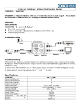
Connection and Communication Setup 1
A When connected to video communication terminal (VIDEO)
b
bb
b Connecting communication conversion connectors
RS-485
MONITOR OUT
MAIN
A
1
IN
2
B
VIDEO
COMSW
ON
1
234
AB
TELEMETRY
12V
3
1
2
1
2
3
3
3
Dome camera
(sold separately)
Zoom camera
(sold separately)
Hard disk digital recorder
with multiplexer function (sold separately)
(A) (B)
Provided communication
conversion connector
Monitor
(sold separately)
AC adapter
(provided)
WH
B
L
S
L
O
R
B
R
B
K
Y
L
R
D
G
R
WH
B
L
S
L
O
R
B
R
B
K
Y
L
R
D
G
R
Green
Red
(A) (B)
Yellow
White

English
Preparation 16
Connection and Communication Setup 1
b
bb
b Making Connections
1
11
1
Connect this unit to equipment
for communication and
operation.
Before connecting, make sure all
equipment is turned off.
2
22
2
Terminate Setup.
SW1: OFF (Fixed)
SW2: OFF (For Camera A)
SW3: OFF (For Camera B)
SW4: ON (For Video)
3
33
3
Connect this unit to its power
source.
1 Connect the DC terminal on the AC
adapter to the power terminal.
2 Plug power plug into AC adapter.
3 Plug power plug into AC power supply.
This unit is turned on, and the main menu
appears on the menu display.
b
bb
b Communication Setup
1
Press the button, then
press the button.
The language selection screen
(LANGUAGE) is displayed. Select a
language if operating in a language other
than English. (P42)
2
Press the button, then
press the button.
Displays the “1–VIDEO” screen for
communications setup
(COMMUNICATIONS).
When communications operations are
performed only through the video
communication terminal (VIDEO) on the
rear of this unit, confirm that the screen is
as shown in Figure 1.
Note: To change the address of this unit
(Keyboard Add), see P44.
• This unit has no power switch.
Turn power ON or OFF by
plugging or unplugging the DC
plug from the AC adapter.
• When a startup password is set,
the password entry screen
appears. (P51)
SW
ON
1
234
VSP-9000
ALARM
PLAY
R PLAY
RECALARM
PLAY STOP
PLAY
SPEED
REC STOP
SEQ
ON
PA N
ON
TOUR
ON
SEQ/
PAN/
TOUR
OFF
ONE PUSH
AF
FOCUS
FAR
FOCUS
NEAR
IRIS
CENTER
GO TO
PRESET
TO SUB
SCREEN
SYSTEM
SETUP
MAP
ENTER
PLAY
SPEED
IRIS
IRIS
ADDRESS ?
DVR
MUX
ADDRESS ?
STILL
TIMER
ON/OFF
CLOCK
ADJUST
CAM 1 DVR 1
CAM 1 DVR 1
SYSTEM
SETUP
SEARCH
COPY
MONITOR
2
MUX
PLAY
ENTERCLEAR
STOP
MENU
TIMER
EXIT/OSD
SEQUENCE
REC STOP REC
ALARM ALARM
AUTOPAN AUTOFLIP
AUX
PROG SCAN
PAT RO L
SYSTEM
STILL
1
DVR
1
ent
1-ITALIANO
> 2-ENGLISH
3-FRANÇAIS
4-DEUTSCH
5-********
6-********
7-********
8-********
9-********
10-********
11-********
12-********
ENABLED:
ENGLISH
ENGLISH
LANGUAGE
LANGUAGE
ent
ent
>1-VIDEO
2-TELEMETRY
3-SERIAL TESTS
COMMUNICATIONS
COMMUNICATIONS
ent
esc
1-VIDEO
1-VIDEO
>Type : DVR/MUX
Protocol : SANYO DVR/MU
Baudrate : 19200
Keyboard Add: 00001
COMMUNICATIONS
COMMUNICATIONS
(Figure 1)

English
17 Preparation
Connection and Communication Setup 1
(continued)
Check Setup:
• Type:
To operate a hard disk digital recorder with
a multiplexer function, this should display
“DVR/MUX”.
• Protocol:
When “DVR/MUX” is selected for “Type”,
“SANYO DVR/MU” is automatically
displayed.
• Baudrate:
“19200” is automatically displayed.
Match the settings of the connected
equipment.
3
Press the button.
Returns to Communication Setup
selection screen.
4
Press the button, select
“2–TELEMETRY”, then press
the button.
The “2–TELEMETRY” screen is
displayed. Check that the settings are as
shown below.
Check Setup:
• A-Connector:
To operate a camera via video equipment,
this should display “Video”.
• A-Protocol:
When “Video” is selected for “A-Connector”,
“SANYO SSP” is automatically displayed.
• A-Baudrate:
Because 1–VIDEO is then set to “Baudrate
(19200)”, “– – – – –” is displayed by default.
5
Press the button.
Returns to Communication Setup
(COMMUNICATIONS).
6
Press the button.
Displays Control Setup (ACCEPTED
VALUES) screen.
For “1–CAMERAS” setup, see P47.
7
Press the button, select
“2–MONITOR/LOCAL
DVR-MUX”, then press the
button.
Set the connected DVR-MUX.
8
This completes the setup.
Proceed to operating the hard
disk digital recorder (P32) or
the camera (P38).
esc
ent
ent
1-VIDEO
>2-TELEMETRY
3-SERIAL TESTS
COMMUNICATIONS
COMMUNICATIONS
ent
esc
2-TELEMETRY
2-TELEMETRY
>A-Connector Video
A-Protocol SANYO SSP
A-Baudrate -----
B-Connector Telemetry
B-Protocol ----------
B-Baudrate -----
COMMUNICATIONS
COMMUNICATIONS
esc
ent
>1-VIDEO
2-TELEMETRY
3-SERIAL TESTS
COMMUNICATIONS
COMMUNICATIONS
ent
(Figure 2)
ent
1-CAMERAS
>2-MONITOR/LOCAL DVR-MUX
3-FUNCTIONS
ACCEPTED VALUES
ACCEPTED VALUES
ent
esc
2-MONITOR/LOCAL DVR-MUX
2-MONITOR/LOCAL DVR-MUX
> 1
11
21
31
41
51
61
71
81
91
ACCEPTED VALUES
ACCEPTED VALUES

English
Preparation 18
Connection and Communication Setup 2
B When connected to video communication terminal (VIDEO)
RS-485
MONITOR OUT
MAIN
A
1
IN
2
B
VIDEO
COMSW
ON
1
234
AB
TELEMETRY
12V
3
1
2
1
2
3
3
3
Dome camera
(sold separately)
Zoom camera
(sold separately)
Zoom camera
(sold separately)
Zoom camera
(sold separately)
Hard disk digital recorder
with multiplexer function (sold separately)
(A) (B)
Provided communication
conversion connectors (Figure 1)
Monitor
(sold separately)
AC adapter
(provided)
Provided communication
conversion connectors
(Figure 2)
WH
B
L
S
L
O
R
B
R
B
K
Y
L
R
D
G
R
B
A
WH
B
L
S
L
O
R
B
R
B
K
Y
L
R
D
G
R
WH
B
L
S
L
O
R
B
R
B
K
Y
L
R
D
G
R
b Connecting communication
conversion connectors (Figure 1)
b
Connecting communication
conversion connectors (Figure 2)
Green
Red
Green
Red
(A) (B)
Yellow
White
Camera

English
19 Preparation
Connection and Communication Setup 2
(continued)
b
bb
b Making Connections
1
11
1
Connect this unit to equipment
for communication and
operation.
Before connecting, make sure all
equipment is turned off.
2
22
2
Terminate Setup.
SW1: OFF (Fixed)
SW2: OFF (For Camera A)
SW3: OFF (For Camera B)
SW4: ON (For Video)
3
33
3
Connect this unit to its power
source.
1 Connect the DC terminal on the AC
adapter to the power terminal.
2 Plug power plug into AC adapter.
3 Plug power plug into AC power supply.
This unit is turned on, and the main menu
appears on the menu display.
b
bb
b Communication Setup
1
Press the button, then
press the button.
The language selection screen
(LANGUAGE) is displayed. Select a
language if operating in a language other
than English. (P42)
2
Press the button, then
press the button.
Displays the “1–VIDEO” screen for
communications setup
(COMMUNICATIONS).
When communications operations are
performed only through the video
communication terminal (VIDEO) on the
rear of this unit, confirm that the screen is
as shown in Figure 1.
Note: To change the address of this unit
(Keyboard Add), see P44.
• This unit has no power switch.
Turn power ON or OFF by
plugging or unplugging the DC
plug from the AC adapter.
• When a startup password is set,
the password entry screen
appears. (P51)
SW
ON
1
234
VSP-9000
ALARM
PLAY
R PLAY
RECALARM
PLAY STOP
PLAY
SPEED
REC STOP
SEQ
ON
PA N
ON
TOUR
ON
SEQ/
PAN/
TOUR
OFF
ONE PUSH
AF
FOCUS
FAR
FOCUS
NEAR
IRIS
CENTER
GO TO
PRESET
TO SUB
SCREEN
SYSTEM
SETUP
MAP
ENTER
PLAY
SPEED
IRIS
IRIS
ADDRESS ?
DVR
MUX
ADDRESS ?
STILL
TIMER
ON/OFF
CLOCK
ADJUST
CAM 1 DVR 1
CAM 1 DVR 1
SYSTEM
SETUP
SEARCH
COPY
MONITOR
2
MUX
PLAY
ENTERCLEAR
STOP
MENU
TIMER
EXIT/OSD
SEQUENCE
REC STOP REC
ALARM ALARM
AUTOPAN AUTOFLIP
AUX
PROG SCAN
PAT RO L
SYSTEM
STILL
1
DVR
1
ent
1-ITALIANO
> 2-ENGLISH
3-FRANÇAIS
4-DEUTSCH
5-********
6-********
7-********
8-********
9-********
10-********
11-********
12-********
ENABLED:
ENGLISH
ENGLISH
LANGUAGE
LANGUAGE
ent
(Figure 1)
ent
>1-VIDEO
2-TELEMETRY
3-SERIAL TESTS
COMMUNICATIONS
COMMUNICATIONS
ent
esc
1-VIDEO
1-VIDEO
>Type : DVR/MUX
Protocol : SANYO DVR/MU
Baudrate : 19200
Keyboard Add: 00001
COMMUNICATIONS
COMMUNICATIONS
/