ALIGNMENTS AND ADJUSTMENT, Continued
Ovens With Constant Pilot
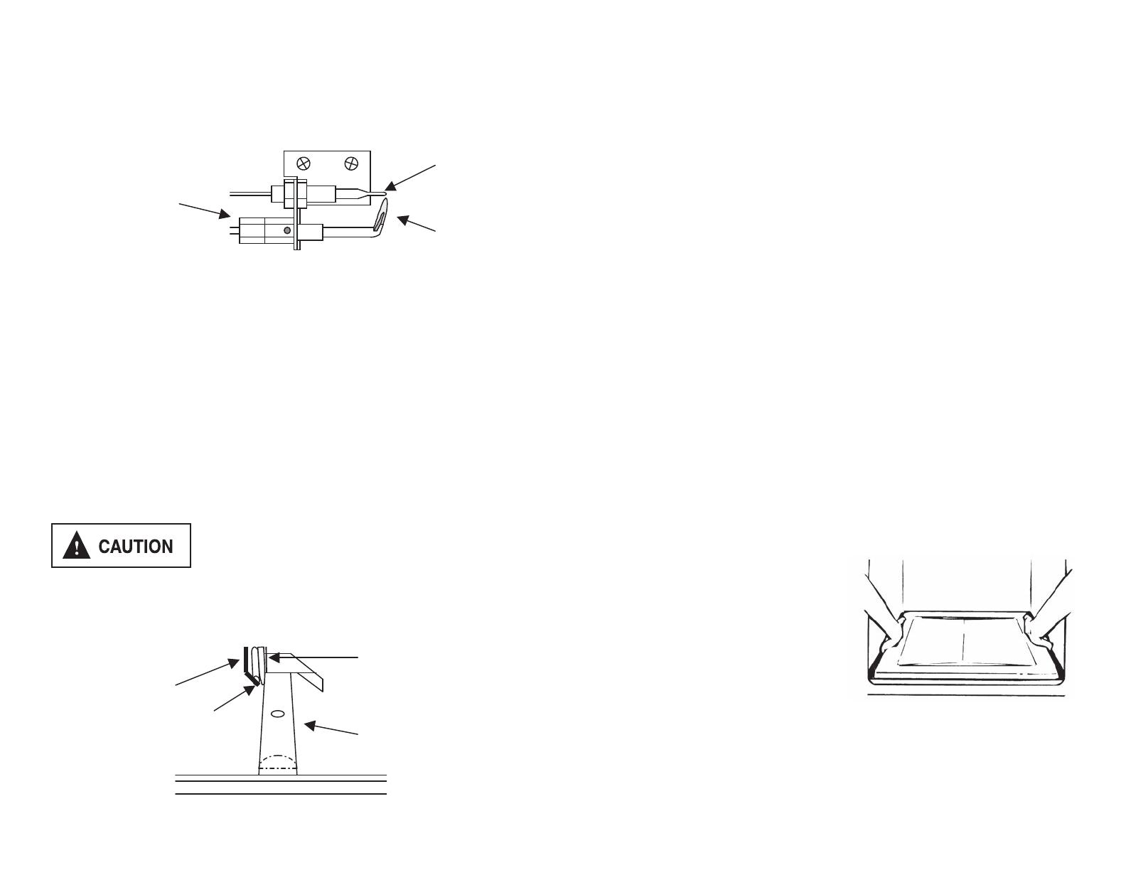
The oven pilot is located along the left hand side of the oven burner. It is fastened under
the flame safety probe. The flame of the oven pilot ignites main burner gas when the
oven is turned on. If the pilot flame is not present, the flame safety device will not allow
pilot gas or main burner gas to flow.
Pilot flame size is set by the adjustment screw located along the side of the thermostat.
The outer tip of the flame should just barely reach the underside of the end of the flame
safety probe. The pilot screw must be adjusted if the range is converted to LP gas.
Light the oven pilot as follows:
• Fully press in and hold the oven control knob to allow pilot gas to flow to the pilot
burner. It will take 30 to 60 seconds to bleed all the air out of the pilot supply line.
• While pressing in the oven control knob, place a lit match or lighter under the pilot
burner to light it.
• Once the pilot burner is lit, continue to hold in the oven control knob for at least 10
seconds.
• If the pilot flame extinguishes when the oven control knob is released, repeat the
above procedure.
• Adjust the size of the oven pilot flame if needed.
ALWAYS LIGHT THE OVEN PILOT WITH ALL CONTROL KNOBS IN THE
“OFF” POSITION.
Make certain the oven is cool when manually lighting
oven pilot.
Ovens with Standby Pilot Battery Spark Ignition: Free-Standing Ranges
Ranges equipped with the battery ignition system have an electrode fastened on the left
hand side of the oven pilot and flame safety probe. In these models, the oven pilot is
used as an ignitor instead of a permanent pilot flame.
ALIGNMENTS AND ADJUSTMENT, Continued
Oven Ignition With Constant Pilot
On ovens with constant pilot ignition, lightly press in the oven control knob and turn it
counterclockwise to the desired temperature setting. If you press the knob in too far to
the pilot lighting position, the knob will not turn. Gently let up on the knob, and the
thermostat shaft will release its safety key to let you rotate the control.
Oven With Standby Pilot Battery Spark Ignition
On ovens with battery spark ignition, turn the oven control knob counterclockwise to the
“STANDBY” position. Fully press in the oven control knob and hold it pressed in for 10
seconds. Pushing in the oven control knob will start all electrodes (top electrodes
included) at a rate of approximately 2 _ pulses per second. While pressing the knob gas
will be introduced at the oven pilot to be lit for use as an oven ignitor.
If you are using the oven for the first time or the oven has not been used in several days,
it may take multiple attempts to successfully light the “STANDBY” ignitor pilot. If the
ignitor pilot will not stay lit after 5 attempts, contact an authorized service technician.
Once the “STANDBY” oven pilot has been lit, lightly press in the oven control knob and
turn it counterclockwise to the desired temperature setting. If you press the knob in too
far to the ignitor lighting position, the knob will not turn. Gently let up on the knob,
and the thermostat shaft will release its safety key to let you rotate the control.
When finished cooking, you may turn the oven control knob back to the “STANDBY”
position. This will turn off the main oven burner, but will keep the oven pilot lit and
ready. If desired, you may turn the knob all the way back to the “OFF” position to shut
off the oven pilot ignitor. If you turn the knob back to the “OFF” position, you must
repeat the battery spark and pilot starting sequence above to use the oven.
If the oven pilot does not ignite and maintain the flame, check for the following:
1. The pilot burner has gone out. Relight the oven pilot.
2. The pilot will not keep the flame safety probe heated. Adjust the size of the pilot
flame. Or, the thermocouple connection at the thermostat may need to be tightened.
3. The flame safety probe may not be properly located. Locate the probe directly
over the pilot burner. On spark ignition ovens, the end of the flame safety probe
must very close to the side of the burner right in front of the flame ports.
4. The pilot burner is not in its proper position. Make sure the rear of the burner is
seated on the injector elbow and the front is bolted onto the burner support.
5. The spark electrode is defective. Contact an authorized service technician.
If the batteries have grown weak and you need to use the oven before you are able to
replace with fresh batteries, the oven can be lit manually. Turn the knob to “STANDBY”
and light the oven pilot as described in the Oven Pilot section.
Hot Oven Restart
If you turn off the oven but then decide to turn it back on before it has cooled to room
temperature, the burner may not light properly. This is due to the thermostat still sensing
a heated oven and not allowing the maximum gas flow rate into the burner. Turn the
control knob all the way to the “BROIL” position to relight the burner. After the burner
lights, you may adjust the oven control to the desired temperature.
Oven Pilot
CAUTION
!
Pilot Burner
Flame Safety Probe
Pilot Flame
Oven Burner
Flame Safety
Probe
Spark Electrode
18
ALIGNMENTS AND ADJUSTMENT, Continued
Ovens With Constant Pilot
The oven pilot is located along the left hand side of the oven burner. It is fastened under
the ame safety probe. The ame of the oven pilot ignites main burner gas when the
oven is turned on. If the pilot ame is not present, the ame safety device will not allow
pilot gas or main burner gas to ow.
Pilot ame size is set by the adjustment screw located along the side of the thermostat.
The outer tip of the ame should just barely reach the underside of the end of the ame
safety probe. The pilot screw must be adjusted if the range is converted to LP gas.
Light the oven pilot as follows:
• Fully press in and hold the oven control knob to allow pilot gas to ow to the pilot
burner. It will take 30 to 60 seconds to bleed all the air out of the pilot supply line.
• While pressing in the oven control knob, place a lit match or lighter under the pilot
burner to light it.
• Once the pilot burner is lit, continue to hold in the oven control knob for at least 10
seconds.
• If the pilot ame extinguishes when the oven control knob is released, repeat the above
procedure.
• Adjust the size of the oven pilot ame if needed.
ALWAYS LIGHT THE OVEN PILOT WITH ALL CONTROL KNOBS IN THE “OFF”
POSITION.
Ovens with Standby Pilot Battery Spark Ignition: Free-Standing Ranges
Ranges equipped with the battery ignition system have an electrode fastened on the left
hand side of the oven pilot and ame safety probe. In these models, the oven pilot is
used as an ignitor instead of a permanent pilot ame.
Make certain the oven is cool when manually lighting
oven pilot.
When baking cakes in glass baking dishes, lower the oven temperature 25ºF to prevent
browning of the bottom and sides before the top becomes brown.
Also when using glass bakeware it would be better to increase the preheat time to have
exact stabilization of the oven’s temperature. To do so allow 20 minutes time for
temperatures up to 350ºF and 30 minutes for temperatures up to 425ºF. Avoid opening the
door as much as possible.
Hot Oven Restart
If you turn off the oven but then decide to turn it back on before it has cooled to room
temperature, the burner may not light properly. This is due to the thermostat still sensing
a heated oven and not allowing the maximum gas ow rate into the burner. Turn the
control knob all the way to the “BROIL” position to relight the burner. After the burner
lights, you may adjust the oven control to the desired temperature.
Oven Racks
The oven racks should be arranged before the oven knob is turned to an “ON” position.
Place the racks so the food is centered in the oven, not the rack.
When more than one utensil is used, be sure to stagger them allowing space between each
one. Do not allow the utensil to touch any part of the oven, especially the glass window.
It is best to use two racks and place food so one utensil is not directly over another.
Rack Removal
Pull the oven rack forward and lift up on the front of the rack so it will clear the rack
keeper.
To replace the oven rack, guide the angled rear portion of the rack under the rack keeper
and slide the rack to the rear.
Never cover the oven racks with aluminum foil. Such practices will trap heat and cause
intense heat in spots which usually give poor results. It can damage the porcelain nish as
well as glass windows in oven doors (if equipped). 11-97
Removable Oven Bottom
First remove the racks from the oven. The
oven bottom lifts from the rear. Grasp each
side of the oven bottom and lift upward from
the rear until the bottom is clear–lift it to
remove from the front.
NOTE: If the oven bottom is replaced
incorrectly it may warp and cause
undesirable baking results.
The oven bottom has a porcelain enamel nish. To make cleaning easier, protect the
oven bottom from excessive spillovers. This is particularly important when baking a fruit
pie or other foods with high acid content. Hot fruit llings or foods that are acidic in
content, such as milk, tomato or sauerkraut, and sauces with vinegar or lemon juice, may
cause pitting and damage to the porcelain enamel surface.
23
When baking cakes in glass baking dishes, lower the oven temperature 25ºF to prevent
browning of the bottom and sides before the top becomes brown.
Also when using glass bakeware it would be better to increase the preheat time to have
exact stabilization of the oven’s temperature. To do so allow 20 minutes time for
temperatures up to 350ºF and 30 minutes for temperatures up to 425ºF. Avoid opening the
door as much as possible.
Hot Oven Restart
If you turn off the oven but then decide to turn it back on before it has cooled to room
temperature, the burner may not light properly. This is due to the thermostat still sensing
a heated oven and not allowing the maximum gas flow rate into the burner. Turn the
control knob all the way to the “BROIL” position to relight the burner. After the burner
lights, you may adjust the oven control to the desired temperature.
Oven Racks
The oven racks should be arranged before the oven knob is turned to an “ON” position.
Place the racks so the food is centered in the oven, not the rack.
When more than one utensil is used, be sure to stagger them allowing space between each
one. Do not allow the utensil to touch any part of the oven, especially the glass window.
It is best to use two racks and place food so one utensil is not directly over another.
Rack Removal
Pull the oven rack forward and lift up on the front of the rack so it will clear the rack
keeper.
To replace the oven rack, guide the angled rear portion of the rack under the rack keeper
and slide the rack to the rear.
Never cover the oven racks with aluminum foil. Such practices will trap heat and cause
intense heat in spots which usually give poor results. It can damage the porcelain finish as
well as glass windows in oven doors (if equipped). 11-97
Removable Oven Bottom
First remove the racks from the oven. The
oven bottom lifts from the rear. Grasp each
side of the oven bottom and lift upward from
the rear until the bottom is clear–lift it to
remove from the front.
NOTE: If the oven bottom is replaced
incorrectly it may warp and cause
undesirable baking results.
The oven bottom has a porcelain enamel finish. To make cleaning easier, protect the
oven bottom from excessive spillovers. This is particularly important when baking a fruit
pie or other foods with high acid content. Hot fruit fillings or foods that are acidic in
content, such as milk, tomato or sauerkraut, and sauces with vinegar or lemon juice, may
cause pitting and damage to the porcelain enamel surface.
23


