Kohler 4EFCD-Low CO Operating instructions
- Category
- Power generators
- Type
- Operating instructions
This manual is also suitable for

Marine Generator Sets
Models:
5ECD/4EFCD--Low CO
7.3ECD/6EFCD--Low CO
TP-6390 1/06a
Operation

TP-6390 1/062
Engine exhaust from this product contains chemicals
known to the State of California to cause cancer, birth
defects, or other reproductive harm.
WARNING
California Proposition 65
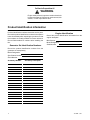
Product Identification Information
Product identification numbers determine service parts.
Record the product identification numbers in the spaces
below immediately after unpacking the products so that
the numbers are readily available for future reference.
Record field-installed kit numbers after installing the
kits.
Generator Set Identificatio n Numbers
Record the product identification numbers from the
generator set nameplate(s).
Model Designation
Specification Number
Serial Number
Accessory Number Accessory Description
Engine Identification
Record the product identification information from the
engine nameplate.
Manufacturer
Model Designation
Serial Number
x:in:007:001

TP-6390 1/06 Table of Contents 3
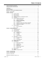
Table of Contents
Product Identification Information 2............................................................
Safety Precautions and Instructions 5........................................................
Introduction 11...............................................................................
Service Assistance 11........................................................................
Maintenance and Service Parts/Related Literature 12............................................
Section 1 Service Views 13...................................................................
Section 2 Operation 15.......................................................................
2.1 Prestart Checklist 15.....................................................
2.2 Marine Inspection 15.....................................................
2.3 Angular Operation 16.....................................................
2.4 Operation in European Union Member Countries 16..........................
2.5 Load Profile 16..........................................................
2.6 Advanced Digital Control Operation 16......................................
2.6.1 Controls and Indicators 16........................................
2.6.2 Starting the Generator Set 17......................................
2.6.3 Stopping the Generator Set 18.....................................
2.6.4 Fault Shutdowns 18..............................................
2.6.5 SmartCraftt System View (SC5000), If Equipped 21.................
2.6.6 Resetting the Controller after a Fault Shutdown 22....................
2.6.7 Continuous Power Mode 22.......................................
2.7 Circuit Protection 22......................................................
2.7.1 Line Circuit Breaker 22...........................................
2.7.2 Fuses 22.......................................................
Section 3 Scheduled Maintenance 23..........................................................
3.1 General Maintenance 23..................................................
3.2 Service Schedule 24.....................................................
3.3 Lubrication System 26....................................................
3.3.1 Oil Specifications 26..............................................
3.3.2 Oil Check 26....................................................
3.3.3 Oil Additions 26..................................................
3.3.4 Oil Change 26...................................................
3.3.5 Oil Filter Change 27..............................................
3.4 Fuel System 27..........................................................
3.4.1 Fuel Specifications 27............................................
3.4.2 Fuel Filter 28....................................................
3.4.3 Fuel System Bleed 28............................................
3.5 Backfire Flame Arrestor 29................................................
3.6 Exhaust System 29......................................................
3.7 Cooling System 30.......................................................
3.7.1 Closed Heat Exchanger 30........................................
3.7.2 Pressure Cap 30.................................................
3.7.3 Seawater Pump 31...............................................
3.7.4 Siphon Break 32.................................................
3.7.5 Anticorrosion Zinc Anode 34.......................................
3.7.6 Seawater Outlet 34...............................................
3.8 Ignition System 35.......................................................
3.9 Battery 37...............................................................
3.10 Generator Storage Procedure 37...........................................
Section 4 Troubleshooting 39.................................................................
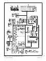
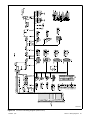
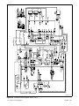
Section 5 Wiring Diagrams 43................................................................
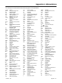
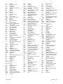
Appendix A Abbreviations 49..................................................................
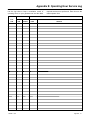
Appendix B Operating Hour Service Log 51.....................................................

TP-6390 1/064

TP-6390 1/06 5Safety Precautions and Instructions
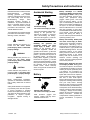
Safety Precautions and Instructions
IMPORTANT SAFETY INSTRUCTIONS.
Electromechanical equipment,
including generator sets, transfer
switches, switchgear, and accessories,
can cause bodily harm and pose
life-threatening danger when
improperly installed, operated, or
maintained. To prevent accidents be
aware of potential dangers and act
safely. Read and follow all safety
precautions and instructions. SAVE
THESE INSTRUCTIONS.
This manual has several types of safety
precautions and instructions: Danger,
Warning, Caution, and Notice.
DANGER
Danger indicates the presence of a
hazard that will cause severe
personal injury, death ,orsubstantial
property damage.
WARNING
Warning indicates the presence of a
hazard that can cause severe
personal injury, death, orsubstantial
property damage.
CAUTION
Caution indicates the presence of a
hazard that will or can cause minor
personal injury or property damage.
NOTICE
Notice communicates installation,
operation, or maintenance information
that is safety related but not hazard
related.
Safety decals affixed to the equipment
in prominent places alert the operator
or service technician to potential
hazards and explain how to act safely.
The decals are shown throughout this
publication to improve operator
recognition. Replace missing or
damaged decals.
Accidental Starting
Accidental starting.
Can cause severe injury or death.
Disconnect the battery cables before
working on the generator set.
Remove the negative (--) lead first
when disconnecting the battery.
Reconnect the negative (--) lead last
when reconnecting the battery.
WARNING
Disabling the generator set.
Accidental starting can cause
severe injury or death. Before
working on the generator set or
connected equipment, disable the
generator set as follows: (1) Move the
generator set master switch to the OFF
position. (2) Disconnect the power to
the battery charger. (3) Remove the
battery cables, negative (--) lead first.
Reconnect the negative (--) lead last
when reconnecting the battery. Follow
these precautions to prevent starting of
the generator set by an automatic
transfer switch, remote start/stop
switch, or engine start command from a
remote computer.
Battery
Sulfuric acid in batteries.
Can cause severe injury or death.
Wear protective goggles and
clothing. Battery acid may cause
blindness and burn skin.
WARNING
Battery electrolyte is a diluted
sulfuric acid. Battery acid can cause
severe injury or death. Battery acid
can cause blindness and burn skin.
Always wear splashproof safety
goggles, rubber gloves, and boots
when servicing the battery. Do not
open a sealed battery or mutilate the
battery case. If battery acid splashes in
the eyes or on the skin, immediately
flush the affected area for 15 minutes
with large quantities of clean water.
Seek immediate medical aid in the case
of eye contact. Never add acid to a
battery after placing the battery in
service, as this may result in hazardous
spattering of battery acid.
Battery acid cleanup. Battery acid
can cause severe injury or death.
Battery acid is electrically conductive
and corrosive. Add 500 g (1 lb.) of
bicarbonate of soda (baking soda) to a
containerwith4L(1gal.)ofwaterand
mix the neutralizing solution. Pour the
neutralizing solution on the spilled
battery acid and continue to add the
neutralizing solution to the spilled
battery acid until all evidence of a
chemical reaction (foaming) has
ceased. Flush the resulting liquid with
water and dry the area.
Battery gases. Explosion can cause
severe injury or death. Battery gases
can cause an explosion. Do not smoke
or permit flames or sparks to occur near
a battery at any time, particularly when
it is charging. Do not dispose of a
battery in a fire. To prevent burns and
sparks that could cause an explosion,
avoid touching the battery terminals
with tools or other metal objects.
Remove all jewelry before servicing the
equipment. Discharge static electricity
from your body before touching
batteries by first touching a grounded
metal surface away from the battery. To
avoid sparks, do not disturb the battery
charger connections while the battery
is charging. Always turn the battery
charger off before disconnecting the
battery connections. Ventilate the
compartments containing batteries to
prevent accumulation of explosive
gases.

TP-6390 1/066 Safety Precautions and Instructions
Battery short circuits. Explosion
can cause severe injury or death.
Short circuits can cause bodily injury
and/or equipment damage.
Disconnect the battery before
generator set installation or
maintenance. Remove all jewelry
before servicing the equipment. Use
tools with insulated handles. Remove
the negative (--) lead first when
disconnecting the battery. Reconnect
the negative (--) lead last when
reconnecting the battery. Never
connect the negative (--) battery cable
to the positive (+) connection terminal
of the starter solenoid. Do not test the
battery condition by shorting the
terminals together.
Engine Backfire/Flash
Fire
Fire.
Can cause severe injury or death.
Do not smoke or permit flames or
sparks near fuels or the fuel system.
WARNING
Servicing the backfire flame
arrester. A sudden backfire can
cause severe injury or death. Do not
operate the generator set with the
backfire flame arrester removed.
Combustible materials. A sudden
flash fire can cause severe injury or
death. Do not smoke or permit flames
or sparks near the generator set. Keep
the compartment and the generator set
clean and free of debris to minimize the
risk of fire. Catch fuels in an approved
container. Wipe up spilled fuels and
engine oil.
Combustible materials. A fire can
cause severe injury or death.
Generator set engine fuels and fuel
vapors are flammable and explosive.
Handle these materials carefully to
minimize the risk of fire or explosion.
Equip the compartment or nearby area
with a fully charged fire extinguisher.
Select a fire extinguisher rated ABC or
BC for electrical fires or as
recommended by the local fire code or
an authorized agency. Train all
personnel on fire extinguisher
operation and fire prevention
procedures.
Engine Fluids and
Chemical Products
Handling caustic engine fluids and
chemical products.
Can cause severe chemical burns,
nausea, fainting, or death.
Most chemicals such as used engine
oil, antifreeze/coolant, rustproofing
agent, inhibiting oil, degreasing
agent, spray paint, and adhesives are
hazardous to health. Read and follow
the user information found on the
packaging. Avoid inhalation and skin
contact. Use only in well-ventilated
areas and use a protective mask
when spraying. Store engine fluids
and chemical products in a locked
cabinet. Contact your local recycling
center for disposal information and
locations.
WARNING
Flammable engine solvents and
cleaners.
Can cause severe injury or death.
Do not smoke or permit flames or
sparks near flammable engine
solvents and cleaners. Read and
follow the user information found on
the packaging. Use only in well-
ventilated areas. Never use gasoline
or low flash-point solvents as
cleaning agents.
WARNING
Leaking or accumulated engine
fluids. A fire can cause severe injury
or death. Clean up engine fluids
including fuel, oil, grease, and coolant.
Determine the source of engine leaks
and correct before starting the
generator set. Keep the generator set
area clean and remove combustible
materials.
Used engine oil. Contact with used
engine oil may cause severe skin
irritation. Repeated and prolonged
skin exposure may have other
health risks. Used engine oil is a
suspected carcinogen. Avoid contact
with skin. Thoroughly wash your hands
and nails with soap and water shortly
after handling used engine oil. Wash or
dispose of clothing or rags containing
used engine oil. Dispose of used
engine oil in a responsible manner.
Contact your local recycling center for
disposal information and locations.

TP-6390 1/06 7Safety Precautions and Instructions
Exhaust System
Carbon monoxide.
Can cause severe nausea,
fainting, or death.
The exhaust system must be
leakproof and routinely inspected.
WARNING
Carbon monoxide symptoms.
Carbon monoxide can cause severe
nausea, fainting, or death. Carbon
monoxide is a poisonous gas present in
exhaust gases. Carbon monoxide
poisoning symptoms include but are
not limited to the following:
D Light-headedness, dizziness
D Physical fatigue, weakness in
joints and muscles
D Sleepiness, mental fatigue,
inability to concentrate
or speak clearly, blurred vision
D Stomachache, vomiting, nausea
If experiencing any of these symptoms
and carbon monoxide poisoning is
possible, seek fresh air immediately
and remain active. Do not sit, lie down,
or fall asleep. Alert others to the
possibility of carbon monoxide
poisoning. Seek medical attention if
the condition of affected persons does
not improve within minutes of breathing
fresh air.
Inspecting the exhaust system.
Carbon monoxide can cause severe
nausea, fainting, or death. For the
safety of the craft’s occupants, install a
carbon monoxide detector. Consult the
boat builder or dealer for approved
detector location and installation.
Inspect the detector before each
generator set use. In addition to routine
exhaust system inspection, test the
carbon monoxide detector per the
manufacturer’s instructions and keep
the detector operational at all times.
Operating the generator set. Carbon
monoxide can cause severe nausea,
fainting, or death. Carbon monoxide
is an odorless, colorless, tasteless,
nonirritating gas that can cause death if
inhaled for even a short time. Use the
following precautions when installing
and operating the generator set. Do not
install the exhaust outlet where exhaust
can be drawn in through portholes,
vents, or air conditioners. Avoid
overloading the craft. If the generator
set exhaust discharge outlet is near the
waterline, water could enter the
exhaust discharge outlet and close or
restrict the flow of exhaust. Never
operate the generator set without a
functioning carbon monoxide detector.
Be especially careful if operating the
generator set when moored or
anchored under calm conditions
because gases may accumulate. If
operating the generator set dockside,
moor the craft so that the exhaust
discharges on the lee side (the side
sheltered from the wind). Always be
aware of others, making sure your
exhaust is directed away from other
boats and buildings.
Fuel System
Explosive fuel vapors.
Can cause severe injury or death.
Use extreme care when handling,
storing, and using fuels.
WARNING
Explosion.
Gasoline vapors can cause
explosion and severe injury or
death.
Before starting the generator set,
operate the blower 4 minutes and
check the engine compartment for
gasoline vapors.
WARNING
Avoid high pressure fluids.
Can cause severe injury or death.
Do not work on high pressure fuel or
hydraulic systems without
protective equipment to protect
hands, eyes, and body. Avoid the
hazard by relieving pressure before
disconnecting fuel injection
pressure lines. Search for leaks
using a piece of cardboard. Always
protect hands, eyes, and body from
high pressure fluids. If an accident
occurs, seek medical attention
immediately.
WARNING

TP-6390 1/068 Safety Precautions and Instructions
The fuel system. Explosive fuel
vapors can cause severe injury or
death. Vaporized fuels are highly
explosive. Use extreme care when
handling and storing fuels. Store fuels
inawell-ventilatedareaawayfrom
spark-producing equipment and out of
the reach of children. Never add fuel to
the tank while the engine is running
because spilled fuel may ignite on
contact with hot parts or from sparks.
Do not smoke or permit flames or
sparks to occur near sources of spilled
fuel or fuel vapors. Keep the fuel lines
and connections tight and in good
condition. Do not replace flexible fuel
lines with rigid lines. Use flexible
sections to avoid fuel line breakage
caused by vibration. Do not operate the
generator set in the presence of fuel
leaks, fuel accumulation, or sparks.
Repair fuel systems before resuming
generator set operation.
Explosive fuel vapors can cause
severe injury or death. Take
additional precautions when using the
following fuels:
Gasoline—Store gasoline only in
approved red containers clearly
marked GASOLINE.
Draining the fuel system. Explosive
fuel vapors can cause severe injury
or death. Spilled fuel can cause an
explosion. Use a container to catch fuel
when draining the fuel system. Wipe up
spilled fuel after draining the system.
Pipe sealant. Explosive fuel vapors
can cause severe injury or death.
Fuel leakage can cause an explosion.
Use pipe sealant on all threaded fittings
to prevent fuel leakage. Use pipe
sealant that resists gasoline, grease,
lubrication oil, common bilge solvents,
salt deposits, and water.
Ignition-protected equipment.
Explosive fuel vapors can cause
severe injury or death. Gasoline
vapors can cause an explosion.
USCG Regulation 33CFR183 requires
that all electrical devices (ship-to-shore
transfer switch, remote start panel,
etc.) must be ignition protected when
used in a gasoline and gaseous-fueled
environment. The electrical devices
listed above are not ignition protected
and are not certified to operate in a
gasoline and gaseous-fueled
environment such as an engine room or
near fuel tanks. Acceptable locations
are the wheelhouse and other living
areas sheltered from rain and water
splash.
Hazardous Noise
Hazardous noise.
Can cause hearing loss.
Never operate the generator set
without a muffler or with a faulty
exhaust system.
CAUTION
Engine noise. Hazardous noise can
cause hearing loss. Wear hearing
protection when near an operating
generator set Prolonged exposure to
noise levels greater than 85 dBA can
cause permanent hearing loss.
Hazardous Voltage/
Electrical Shock
Hazardous voltage.
Can cause severe injury or death.
Operate the generator set only when
all guards and electrical enclosures
areinplace.
Moving rotor.
WARNING
Grounding electrical equipment.
Hazardous voltage can cause
severe injury or death. Electrocution
is possible whenever electricity is
present. Turn off the main circuit
breakers of all power sources before
servicing the equipment. Configure the
installation to electrically ground the
generator set, transfer switch, and
related equipment and electrical
circuits to comply with applicable codes
and standards. Never contact
electrical leads or appliances when
standing in water or on wet ground
because these conditions increase the
risk of electrocution.

TP-6390 1/06 9Safety Precautions and Instructions
Disconnecting the electrical load.
Hazardous voltage can cause
severe injury or death. Disconnect
the generator set from the load by
opening the line circuit breaker or by
disconnecting the generator set output
leads from the t ransfer switch and
heavily taping the ends of the leads.
High voltage transferred to the load
during testing may cause personal
injury and equipment damage. Do not
use the safeguard circuit breaker in
place of the line circuit breaker. The
safeguard circuit breaker does not
disconnect the generator set from the
load.
Short circuits. Hazardous
voltage/current can cause severe
injury or death. Short circuits can
cause bodily injury and/or equipment
damage. Do not contact electrical
connections with tools or jewelry while
making adjustments or repairs.
Remove all jewelry before servicing the
equipment.
Electrical backfeed to the utility.
Hazardous backfeed voltage can
cause severe injury or death.
Connect the generator set to the
building/marina electrical system only
through an approved device and after
the building/marina main switch is
opened. Backfeed connections can
cause severe injury or death to utility
personnel working on power lines
and/or personnel near the work area.
Some states and localities prohibit
unauthorized connection to the utility
electrical system. Install a
ship-to-shore transfer switch to prevent
interconnection of the generator set
power and shore power.
Testing live electrical circuits.
Hazardous voltage or current can
cause severe injury or death. Have
trained and qualified personnel take
diagnostic measurements of live
circuits. Use adequately rated test
equipment with electrically insulated
probes and follow the instructions of the
test equipment manufacturer when
performing voltage tests. Observe the
following precautions when performing
voltage tests: (1) Remove all jewelry.
(2) Stand on a dry, approved electrically
insulated mat. (3) Do not touch the
enclosure or components inside the
enclosure. (4) Be prepared for the
system to operate automatically.
(600 volts and under)
Hot Parts
Hot coolant and steam.
Can cause severe injury or death.
Before removing the pressure cap,
stop the generator set and allow it to
cool. Then loosen the pressure cap
to relieve pressure.
WARNING
Hot engine and exhaust system.
Can cause severe injury or death.
Do not work on the generator set until
it cools.
WARNING
Hot engine oil.
Can cause severe injury or death.
Avoid skin contact with hot oil. Do not
start or operate the generator set with
the engine oil filler cap removed, as
hot oil can spray out. Ensure that the
lubrication system is not under
pressure when servicing. Do not
work on the generator set until it
cools.
WARNING
Checking the coolant level. Hot
coolant can cause severe injury or
death. Allow the engine to cool.
Release pressure from the cooling
system before removing the pressure
cap. To release pressure, cover the
pressure cap with a thick cloth and then
slowly turn the cap counterclockwise to
the first stop. Remove the cap after
pressure has been completely
released and the engine has cooled.
Check the coolant level at the tank if the
generator set has a coolant recovery
tank.
Servicing the exhaust system. Hot
parts can cause severe injury or
death. Do not touch hot engine parts.
The engine and exhaust system
components become extremely hot
during operation.
Moving Parts
Hazardous voltage.
Can cause severe injury or death.
Operate the generator set only when
all guards and electrical enclosures
areinplace.
Moving rotor.
WARNING

TP-6390 1/0610 Safety Precautions and Instructions
Rotating parts.
Can cause severe injury or death.
Operate the generator set only when
all guards, screens, and covers are in
place.
WARNING
Airborne particles.
Can cause severe injury or
blindness.
Wear protective goggles and clothing
when using power tools, hand tools,
or compressed air.
WARNING
Tightening the hardware. Flying
projectiles can cause severe injury
or death. Loose hardware can cause
the hardware or pulley to release from
the generator set engine and can cause
personal injury. Retorque all
crankshaft and rotor hardware after
servicing. Do not loosen the crankshaft
hardware or rotor thrubolt when making
adjustments or servicing the generator
set. Rotate the crankshaft manually in
a clockwise direction only. Turning the
crankshaft bolt or rotor thrubolt
counterclockwise can loosen the
hardware.
Servicing the generator set when it
is operating. Exposed moving parts
can cause severe injury or death.
Keep hands, f eet, hair, clothing, and
test leads away from the belts and
pulleys when the generator set is
running. Replace guards, screens, and
covers before operating the generator
set.
Sound shield removal. Exposed
moving parts can cause severe
injury or death. The generator set
must be operating in order to perform
some scheduled maintenance
procedures. Be especially careful if the
sound shield has been removed,
leaving the belts and pulleys exposed.
(Sound-shield-equipped models only)
Notice
NOTICE
Hardware damage. The engine and
generator set may use both American
Standard and metric hardware. Use
the correct size tools to prevent
rounding of the bolt heads and nuts.
NOTICE
When replacing hardware, do not
substitute with inferior grade
hardware. Screws and nuts are
available in different hardness ratings.
To indicate hardness, American
Standard hardware uses a series of
markings, and metric hardware uses a
numeric system. Check the markings
on the bolt heads and nuts for
identification.
NOTICE
Electrostatic discharge damage.
Electrostatic discharge (ESD)
damages electronic circuit boards.
Prevent electrostatic discharge
damage by wearing an approved
grounding wrist strap when handling
electronic circuit boards or integrated
circuits. An approved grounding wrist
strap provides a high resistance (about
1 megohm), not a direct short,to
ground.
NOTICE
Fuse replacement. Replace fuses
with fuses of the same ampere rating
and type (for example: 3AB or 314,
ceramic). Do not substitute clear
glass-type fuses for ceramic fuses.
Refer to the wiring diagram when the
ampere rating is unknown or
questionable.
NOTICE
Saltwater damage. Saltwater quickly
deteriorates metals. Wipe up saltwater
on and around the generator set and
remove salt deposits from metal
surfaces.

TP-6390 1/06 11Introduction
Introduction
This manual provides operation instructions for
5/7.3ECD and 4/6EFCD model generator sets.
Refer to the engine operation manual for generator set
engine scheduled maintenance information.
Information in this publication represents data available
at the time of print. Kohler Co. reserves the right to
change this publication and the products represented
without notice and without any obligation or liability
whatsoever.
Read this manual and carefully follow all procedures
and safety precautions to ensure proper equipment
operation and to avoid bodily injury. Read and follow the
Safety Precautions and Instructions section at the
beginning of this manual. Keep this manual with the
equipment for future reference.
The equipment service requirements are very important
to safe and efficient operation. Inspect the parts often
and perform required service at the prescribed intervals.
Obtain service from an authorized service
distributor/dealer to keep equipment in top condition.
Before installing a marine generator set, obtain the
most current installation manual from your local
distributor/dealer. Only qualified persons should
install the generator set.
x:in:001:002:a
Service Assistance
For professional advice on generator power
requirements and conscientious service, please contact
your nearest Kohler distributor or dealer.
D Consult the Yellow Pages under the heading
Generators—Electric
D Visit the Kohler Power Systems website at
KohlerPowerSystems.com
D Look at the labels and stickers on your Kohler product
or review the appropriate literature or documents
included with the product
D Call toll free in the US and Canada 1-800-544-2444
D Outside the US and Canada, call the nearest regional
office
Headquarters Europe, Middle East, Africa
(EMEA)
Kohler Power Systems
ZI Senia 122
12, rue des Hauts Flouviers
94517 Thiais Cedex
France
Phone: (33) 1 41 735500
Fax: (33) 1 41 735501
Asia Pacific
Power Systems Asia Pacific Regional Office
Singapore, Republic of Singapore
Phone: (65) 6264-6422
Fax: (65) 6264-6455
China
North China Regional Office, Beijing
Phone: (86) 10 6518 7950
(86) 10 6518 7951
(86) 10 6518 7952
Fax: (86) 10 6518 7955
East China Regional Office, Shanghai
Phone: (86) 21 6288 0500
Fax: (86) 21 6288 0550
India, Bangladesh, Sri Lanka
India Regional Office
Bangalore, India
Phone: (91) 80 3366208
(91) 80 3366231
Fax: (91) 80 3315972
Japan, Korea
North Asia Regional Office
Tokyo, Japan
Phone: (813) 3440-4515
Fax: (813) 3440-2727
Latin America
Latin America Regional Office
Lakeland, Florida, USA
Phone: (863) 619-7568
Fax: (863) 701-7131

TP-6390 1/0612 Maintenance and Service Parts/Related Literature
Maintenance and Service Parts/Related Literature
Maintenance and Service Parts
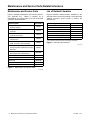
Figure 1 identifies maintenance and service parts for
your generator set. Obtain a complete list of
maintenance and service parts from your authorized
generator distributor/dealer.
Part Description Part Number
Fuse, (F1) 10 amp,
Auxiliary Winding
358337
Fuse, (F2) 10 amp,
Controller
223316
Fuse, (F3) 10 amp,
Customer Connection
223316
Fuse, (F4) 15 amp,
Coils/Injectors
283645
Fuse, (F5) 15 amp,
ECM, O
2
Sensor, and Fuel Pumps
283645
Fuse, (F6) 15 amp,
Voltage Regulator and Battery Charging
Alternator
283645
Fuse, (F7) 20 amp,
Starter Motor and Crank Solenoid
GM39266
Oil Filter 359771
Seawater Pump Impeller Kit 359978
Spark Plug GM46180
Spray Paint (White) 221335
Zinc Anode 260085
Figure 1 Maintenance and Service Parts
x:in:001:004
List of Related Literature
Figure 2 identifies related literature available for the
generator sets covered in this manual. Only trained and
qualified personnel should install or service the
generator set.
Literature Type Part Number
Installation Manual TP-5982
Operation Manual (Generator) TP-6390
Operation Manual (Engine) TP-6001
Parts Catalog* TP-5987
Service Manual (Generator) TP-6391
Service Manual (Engine) TP-6002
Service Manual Supplement (Engine) TP-6008
* One manual combines Generator and Engine information.
Figure 2 Generator Set Literature
x:in:001:005

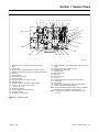
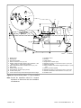
TP-6390 1/06 13Section 1 Service Views
Section 1 Service Views
15
2
20
28 27
22
25
29
4
30
10 11
12
18
17
13
9
21
26
87
SERVICE VIEW
1 3
19
1. Spark plug (also one located on the nonservice side)
2. Oil fill
3. Overflow tube
4. Pressure cap (coolant fill location after draining coolant)
5. Seawater pressure switch (appears as auxiliary fault on ADC)
6. Lifting eye
7. Heat exchanger
8. Anticorrosion zinc anode
9. AC circuit breaker
10. AC load lead connector (nonservice side)
11. Nameplate (top)
12. Customer interface connection (nonservice side)
13. Fuses (F1, F2, F3, F4, F5, F6, and F7)
(see Section 2.7.2)
14. Runtime hour display
15. Advanced Digital Control (ADC 2100)
16. CO sensor module
17. Generator set master switch
18. Catalyst assembly, water outlet/exhaust outlet (nonservice
side)
19. Seawater drain (remove plate for service)
20. Seawater pump (water inlet)
21. Cooling air inlet
22. Fuel filter/fuel inlet
23. Fuel pump
24. Fuel pump/cooler
25. Oil check
26. Coolant drain (remove hose clamp to drain coolant)
27. Oil drain valve
28. Lube oil filter
29. Coolant overflow bottle (daily coolant check/fill location)
30. Air intake silencer/backfire flame arrestor
Note: Consult installation drawings in Spec Sheet or Installation
Manual for fuel- and battery-connection points.
Note: Consult distributor/dealer or Service Manual for items
not shown.
24
5
14
23
6
ADV7025A-A
16
Figure 1-1 Service Views

TP-6390 1/0614 Section 1 Service Views
Notes

TP-6390 1/06 15Section 2 Operation
Section 2 Operation
2.1 Prestart Checklist
To ensure continued satisfactory operation perform the
following checks or inspections before or at each
startup, as designated, and at the intervals specified in
the service schedule. In addition, some checks require
verification after the unit starts.
Air Inlets. Check for clean and unobstructed air inlets.
Air Shrouding. Check for securely installed and
positioned air shrouding.
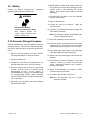
Backfire Flame Arrester. Check for a clean and
installed backfire flame arrester to prevent unfiltered air
from entering the engine.
Battery. Check for tight battery connections. Consult
the battery manufacturer’s instructions regarding
battery care and maintenance.
Coolant Level. Check the coolant level according to
the cooling system maintenance information.
Exhaust System. Check for exhaust leaks and
blockages. Check the silencer and piping condition and
check for tight exhaust system connections.
Inspect the exhaust system components (exhaust
manifold, catalyst, exhaust hose, hose clamps, silencer,
and outlet flapper) for cracks, leaks, and corrosion.
D Check the hoses for softness, cracks, leaks, or dents.
Replace the hoses as needed.
D Check for corroded or broken metal parts and replace
them as needed.
D Check for loose, corroded, or missing clamps.
Tighten or replace the hose clamps and/or hangers
as needed.
D Check that the exhaust outlet is unobstructed.
D Visually inspect for exhaust leaks (blowby). Check
for carbon or soot residue on exhaust components.
Carbon and soot residue indicates an exhaust leak.
Seal leaks as needed.
D Ensure that the carbon monoxide detector(s) is (1) in
the craft, (2) functional, and (3) energized whenever
the generator set operates.
For your safety: Never operate the generator set
without a functioning carbon
monoxide detector(s) for your
safety and the safety of others on
your vessel.
Fuel Level. Check the fuel level and keep the tank(s)
full to ensure adequate fuel supply.
Oil Level. Maintain the oil level at or near, not over, the
full mark on the dipstick.
Operating Area. Check for obstructions that could
block the flow of cooling air. Keep the air intake area
clean. Do not leave rags, tools, or debris on or near the
generator set.
Seawater Pump Priming. Prime the seawater pump
before initial startup. To prime the pump: (1) close the
seacock, (2) remove the hose from the water-filter
outlet, (3) fill the hose and seawater pump with clean
water, (4) reconnect the hose to the water filter outlet,
and (5) open the seacock. Confirm seawater pump
operation on startup as indicated by water discharge
from the exhaust outlet.
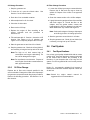
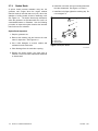
2.2 Marine Inspection
Kohler Co. recommends that all boat owners have their
vessels inspected at the start of each boating season by
the US Coast Guard, the local Coast Guard Auxiliary, or
local state agency.
Kohler Co. also recommends having the generator’s
exhaust system inspected at the start of each boating
season by an authorized Kohlerr distributor/dealer.
Repair any problems identified before operating the
generator set.
Carbon monoxide.
Can cause severe nausea,
fainting, or death.
The exhaust system must be
leakproof and routinely inspected.
WARNING

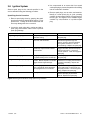
TP-6390 1/0616 Section 2 Operation
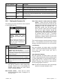
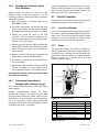
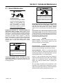
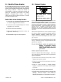
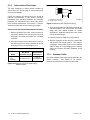
2.3 Angular Operation
See Figure 2-1 for angular operation limits for units
covered in this manual.
Continuous
Intermittent—
3 minutes or less
25_ 30_
Maximum value for all directions
Figure 2-1 Angular Operation
2.4 Operation in European Union
Member Countries
This generator set is specifically intended and approved
for operation below the deck in the engine compartment.
Operation above the deck and/or outdoors would
constitute a violation of European Union Directive
2000/14/EC noise emission standard.
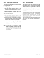
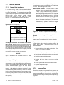
2.5 Load Profile
Whenever operating the generator set, Kohler Co.
recommends maintaining the minimum load profile
indicated in Figure 2-2. Maintaining the load profile
prevents corrosion formation on internal engine
components when they’re exposed to the breakdown of
exhaust gases.
Minimum
Load Requirement
Ideal
Load Requirement
30% load 70% load or more
Figure 2-2 Load Profile
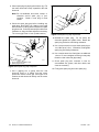
The operator should perform all of the prestart checks.
Start the generator set according to the starting
procedure in the controller section of this manual. While
the generator set is operating, listen for a
smooth-running engine and visually inspect the
generator set for fluid or exhaust leaks.
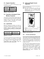
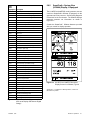
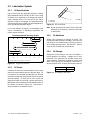
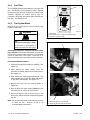
2.6 Advanced Digital Control
Operation
Figure 2-3 illustrates the user interface on the Advanced
Digital Control (ADC 2100).
Note: Have setup and adjustments of the ADC 2100
performed only by an authorized Kohler
distributor/dealer. The setup and adjustments
are password protected.
GM28707A-C
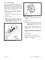
1. LED display
2. Up and down arrow buttons (use for setup and adjustment
only)
3. Generator set master switch
4. Select button (use for setup and adjustment only)
1
4
3
2
Figure 2-3 ADC 2100 Control
2.6.1 Controls and Indicators
Figure 2-4 describes the controls and indicators located
on the controller. The LED display indicates generator set
status as shown in Figure 2-4. The display is active when
the master switch is in the RUN or AUTO position and
remains active until the generator set master switch is
moved to the OFF/RESET position or the power to the
controller is removed.
The buttons on the controller keypad are used only for
system configuration and adjustment. The controller is
factory-set and should not require configuration or
adjustment under normal operating conditions. If the
generator set is reconnected to a different voltage
and/or frequency, refer to an authorized Kohler
distributor/dealer for system configuration and
adjustment instructions.

TP-6390 1/06 17Section 2 Operation
Control or Indicator Item Description
LED display
Runtime hours Displays total generator set runtime hours.
p
y
Crank indication Displays CC_1, CC_2, or CC_3 to indicate the first, second or third attempt to start the
engine. The last digit flashes during the crank cycle rest periods.
Fault codes Flashes a 2- or 3-letter fault code to indicate various fault conditions. See Section 2.6.4.
Software version See TP-5982, Generator Set Installation Manual.
Keypad Select and arrow
buttons
The keypad is used for controller setup and adjustment only. Have setup and adjustments
performed only by an authorized distributor/dealer. T he setup and adjustment functions are
password-protected.
Generator set master
switch
Three-position
switch
Switch functions as the generator set operation and controller reset switch.
Figure 2-4 ADC 2100 Controls and Indicators
2.6.2 Starting the Generator Set
The following procedures describe the actions required
to start the generator set.
Explosion.
Gasoline vapors can cause
explosion and severe injury or
death.
Before starting the generator set,
operate the blower 4 minutes and
check the engine compartment for
gasoline vapors.
WARNING
S
t
e
p
A
c
t
i
o
n
Step
A
ction
1 Operate the blower.
Operate the blower 4 minutes and check the engine
compartment for gasoline vapors.
NOTE: Many boat manufacturers recommend
continuous blower operation while the generator set
is operating. Read the vessel’s owner’s manual for
further information.
2 Open the fuel shut-off valve.
Open the manual fuel shut-off valve, if equipped.
3 Start the generator set
Place the generator set master switch to the RUN
position.
Note: Opening seacock. Before starting the generator
set, open the seacock to allow cooling water
passage. Failure to do so could damage the
seawater pump impeller and cause serious
engine overheating damage.
Note: Transfer switch. Check that the marine
ship-to-shore transfer switch, if equipped, is in
the ship position.
Note: Close seacock if water enters the exhaust
system. If water enters the exhaust system,
close the seacock and drain the water from the
exhaust system at the silencer’s drain plug before
attempting to start the generator set. A
water-filled exhaust hose and silencer may
hinder generator starting and cause seawater
entry into the engine cylinders through the
exhaust valves. Water ingested into the engine
may cause major engine damage that the Kohler
Co. warranty does not cover. If excessive
cranking is a chronic problem, have the unit,
including the exhaust system, serviced by an
authorized Kohlerr distributor/dealer.
The controller attempts to start the generator set three
times. If the generator set does not start in three
attempts, the system shuts down on an overcrank fault.
Local Starting.
Move the generator set master switch to the RUN
position. The ADC 2100 attempts to start the generator
set in three crank cycles (crank cycle time is
pre-programmed).
Auto (Automatic) Starting.
Move the generator set master switch to the AUTO
position to allow startup by the remote start/stop switch
or remote digital gauge. A remote start/stop switch or
digital gauge can be connected to the customer
interface connection (P21 connector, leads 3 and 4).
See the wiring diagram in Section 5.
Note: The ADC 2100 allows three crank cycle attempts
before the overcrank shutdown occurs.

TP-6390 1/0618 Section 2 Operation
2.6.3 Stopping the Generator Set
The following procedures describe the actions required
to stop the generator set.
Local Stopping
1. Run the generator set at no load for at least
2 minutes to ensure adequate engine cooldown.
2. Move the generator set master switch to the
OFF/RESET position. The engine stops.
Auto (Automatic) Stopping.
1. Run the generator set at no load for at least
2 minutes to ensure adequate engine cooldown.
2. With the generator set master switch in the AUTO
position, the generator set stops when the remote
start/stop switch contacts close momentarily.
Note: If the ADC 2100 is configured for a digital gauge,
the controller will not power down (if the master
switch is in the AUTO position). See
Section 2.6.7.
Note: If the ADC 2100 is not configured for a digital
gauge, the controller will power down after
48 hours (if the master switch is in the AUTO
position). If the generator has been started, the
controller will power down 48 hours after the
generator stops.
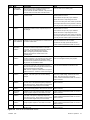
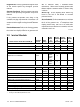
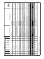
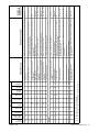
2.6.4 Fault Shutdowns
The generator set shuts down automatically under the
fault conditions listed in Figure 2-5 and the controller
displays a fault code. The generator set cannot be
restarted until the fault condition is corrected and the
controller is reset. See Section 2.6.6 to reset the
controller after a fault shutdown. The controller resets
automatically after a battery voltage fault condition is
corrected.
Shutdown switches on the generator set automatically
reset when the problem is corrected. The high engine
temperature switch automatically resets when the
generator set cools. However, the fault does not clear
until the controller is reset.
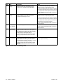
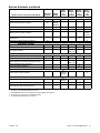
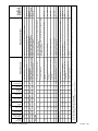
The controller displays a fault code but the generator set
does not shut down under the conditions shown in
Figure 2-6.

TP-6390 1/06 19Section 2 Operation
Code Fault Description Check
AF Auxiliary fault
input shutdown
Input from a customer-supplied switch that closes
when the fault is active. Shutdown occurs
0.3 seconds after the fault is detected. This protection
becomes active 3-seconds after crank disconnect.
Check the cause of the auxiliary fault.
CO-1 Carbon monoxide
shutdown
Sensor fault shutdown occurs because of the
presence of CO.
Immediate service required. Contact an authorized
distributor/dealer for service.
Ensure windows are open for proper ventilation.
Operate the blower to expel dangerous fumes.
Move the vessel away from other vessels (as another
vessel may be the source for the presence of the CO).
Check the generator exhaust system (see Section 3.6).
CO-2 Carbon monoxide
shutdown
Shutdown occurs because of the presence of CO or
deteriorating emission-control components (such as
the catalyst).
Immediate service required. Contact an authorized
distributor/dealer for service.
Ensure windows are open for proper ventilation.
Operate the blower to expel dangerous fumes.
Move the vessel away from other vessels (as another
vessel may be the source for the presence of the CO).
Check the generator exhaust system (see Section 3.6).
CO-3 Carbon monoxide
sensor shutdown
Shutdown occurs if communication is lost between the
CO sensor and the ADC.
Check the connections to the CO sensor.
If connections are okay, replace the CO sensor.
Contact an authorized distributor/dealer for service.
HE High engine
temperature
shutdown
Shutdown occurs if the engine coolant temperature
exceeds the maximum temperature for more than
5 seconds. This protection becomes active after the
engine reaches the crank disconnect speed.
Note: The high engine temperature shutdown
functions only when the coolant level is in the
operating range.
Check for a low engine coolant level.
LOC Loss of coolant
shutdown
Shutdown occurs 5 seconds after a loss of coolant
condition is detected. This protection becomes active
10 seconds after the engine has reached its stated
crank disconnect speed and remains active as long as
the generator run command is active.
Check for a clogged seawater intake or sea strainer.
Check for a damaged seawater pump impeller.
LOP Low oil pressure
shutdown
Shutdown occurs if a low oil pressure condition exists
for more than 5 seconds. This protection becomes
active 30 seconds after the engine has reached crank
disconnect speed (30 second inhibit).
Note: The low oil pressure shutdown does not protect
against low oil level. Check the oil level at the engine.
Check for leaks in the lubrication system.
Check the oil level and add oil if the level is low.
OC Overcrank
shutdown
Shutdown occurs after 3 unsuccessful starting
attempts. The crank cycle is set for three starting
attempts.
Check the fuel supply and battery.
If there is no output voltage, check the line circuit
breaker. Also check for loose connections.
Contact an authorized distributor/dealer for service if
problem continues.
OF Overfrequency
shutdown
Shutdown occurs when the governed frequency
exceeds 110% of the system’s frequency setpoint for
more than 5 seconds. This protection becomes active
10 seconds after engine start (10 second inhibit).
Contact an authorized distributor/dealer for service if
problem continues.
OS Overspeed
shutdown
Shutdown occurs if the engine speed exceeds 115%
of the normal running speed for more than 0.3 seconds.
Contact an authorized distributor/dealer for service if
problem continues.
OU Overvoltage
shutdown
Shutdown occurs if the voltage exceeds 120% of the
voltage regulator setpoint for more than 2 seconds.
Contact an authorized distributor/dealer for service if
problem continues.
UF Underfrequency
shutdown
Shutdown occurs when the governed frequency falls
below 90% of the system’s frequency setpoint for
more than 5 seconds. This protection becomes active
10 seconds after engine start (10-second inhibit).
Reduce the load and restart the generator set.
Contact an authorized distributor/dealer for service if
problem continues.
UU Undervoltage
shutdown
Shutdown occurs if the voltage falls below 80% of the
voltage regulator setpoint for more than 10 seconds.
Reduce the load and restart the generator set.
Contact an authorized distributor/dealer for service if
problem continues.
SCF0 Controller error Indicates a software or communication problem within
the ADC 2100.
Contact an authorized distributor/dealer for service if
problem continues.
Figure 2-5 ADC 2100 Fault Shutdown Codes

TP-6390 1/0620 Section 2 Operation
Code Fault Description Check
CO-4 Carbon monoxide
warning
Fault code is displayed if the presence of CO is
detected because of the time-weighted average
presence of CO. Activates the CO cabin alarms.
Ensure windows are open for proper ventilation.
Operate the blower to expel dangerous fumes.
Move the vessel away from other vessels (as another
vessel may be the source for the presence of the CO).
Check the generator exhaust system (see Section 3.6).
Contact an authorized distributor/dealer for service if
problem continues.
CO-5 Carbon monoxide
warning
Fault code is displayed if the presence of CO is
detected. Warning occurs if the sensor detects
acceptable but increasing CO levels.
Ensure windows are open for ventilation.
Operate the blower to expel dangerous fumes.
Move the vessel away from other vessels (as another
vessel may be the source for the presence of the CO).
Check the generator exhaust system (see Section 3.6).
Generator service for emissions required.
Contact an authorized distributor/dealer for service if
problem continues.
CO-6 Carbon monoxide
sensor warning
Fault code is displayed if the CO sensor is inoperative. Replace the CO sensor.
Contact an authorized distributor/dealer for service if
problem continues.
HB High battery
voltage warning
Fault code is displayed if the engine starting battery
voltage rises above 16 VDC for a 12 VDC system or
above 30 VDC for a 24 VDC system for more than
2 seconds when the engine is not running. This fault
condition does not inhibit engine starting.
The fault condition clears when the battery voltage
returns to a voltage within the limits for more than
2 seconds.
Check the battery rating and condition.
LB Low battery
voltage warning
Fault code is displayed if the engine starting battery
voltage falls below 9.5 VDC for a 12 VDC system or
below 16 VDC for a 24 VDC system for more than
2 seconds when the engine is not running. This fault
condition does not inhibit engine starting.
The fault condition clears when the battery voltage
returns to a voltage within the limits for more than
2 seconds.
Check the battery rating and condition.
Charge or replace the battery.
Figure 2-6 ADC 2100 Fault Warning Codes
Page is loading ...
Page is loading ...
Page is loading ...
Page is loading ...
Page is loading ...
Page is loading ...
Page is loading ...
Page is loading ...
Page is loading ...
Page is loading ...
Page is loading ...
Page is loading ...
Page is loading ...
Page is loading ...
Page is loading ...
Page is loading ...
Page is loading ...
Page is loading ...
Page is loading ...
Page is loading ...
Page is loading ...
Page is loading ...
Page is loading ...
Page is loading ...
Page is loading ...
Page is loading ...
Page is loading ...
Page is loading ...
Page is loading ...
Page is loading ...
Page is loading ...
Page is loading ...
Page is loading ...
Page is loading ...
Page is loading ...
Page is loading ...
-
 1
1
-
 2
2
-
 3
3
-
 4
4
-
 5
5
-
 6
6
-
 7
7
-
 8
8
-
 9
9
-
 10
10
-
 11
11
-
 12
12
-
 13
13
-
 14
14
-
 15
15
-
 16
16
-
 17
17
-
 18
18
-
 19
19
-
 20
20
-
 21
21
-
 22
22
-
 23
23
-
 24
24
-
 25
25
-
 26
26
-
 27
27
-
 28
28
-
 29
29
-
 30
30
-
 31
31
-
 32
32
-
 33
33
-
 34
34
-
 35
35
-
 36
36
-
 37
37
-
 38
38
-
 39
39
-
 40
40
-
 41
41
-
 42
42
-
 43
43
-
 44
44
-
 45
45
-
 46
46
-
 47
47
-
 48
48
-
 49
49
-
 50
50
-
 51
51
-
 52
52
-
 53
53
-
 54
54
-
 55
55
-
 56
56


Kohler 4EFCD-Low CO Operating instructions
- Category
- Power generators
- Type
- Operating instructions
- This manual is also suitable for
Ask a question and I''ll find the answer in the document
Finding information in a document is now easier with AI
Related papers
-
Kohler 600REOZVB Operating instructions
-
Kohler Aegis LV680 User manual
-
-
-
-
-
-
-
-
Other documents
-
Alpha AlphaGen Curbside Owner's manual
-
Lennox RGEN12 Operating instructions
-
-
Snap-On SR3000 User manual
-
 Solé Diesel 4 GSCH v1 User manual
-
Total TBC1601 Owner's manual
-
-
CUMMINS QG 4000/3600 LP KY Installation guide
-
Wacker Neuson LTV6K User manual
-
Briggs & Stratton ELITE Series User manual
