<YRD5315-A> 1 <YRD5315-A> 2 <YRD5315-A> 3 <YRD5315-A> 4
CD RECEIVER
AUTORADIO CD
RADIO CD
DEH-P6200BT
Connecting the unit English
WARNING
• Use speakers over 50 W (output value) and
between 4 W to 8
W (impedance value). Do not use
1 W to 3
W speakers for this unit.
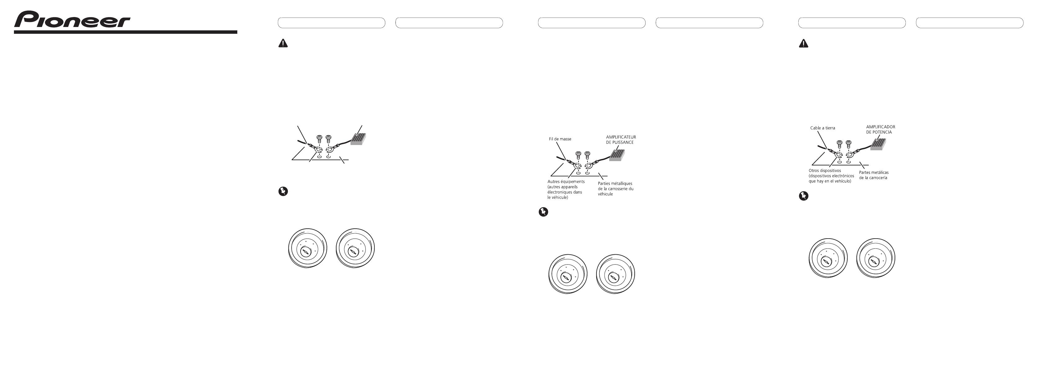
• The black cable is ground. When installing this
unit or power amp (sold separately), make sure
to connect the ground wire first. Ensure that
the ground wire is properly connected to metal
parts of the car’s body. The ground wire of the
power amp and the one of this unit or any other
device must be connected to the car separately
with different screws. If the screw for the ground
wire loosens or falls out, it could result in fire,
generation of smoke or malfunction.
Ground wire
Metal parts of car’s body
Other devices
(Another electronic
device in the car)
POWER AMP
Important
• When this unit is installed in a vehicle without
ACC (accessory) position on the ignition switch,
red cable must be wired to the terminal that can
detect the operation of the ignition key. Otherwise,
battery drain may result.
ACC position
No ACC position
• Use this unit with a 12-volt battery and negative
grounding only. Failure to do so may result in a
fire or malfunction.
• To prevent short-circuit, overheating or
malfunction, be sure to follow the directions
below.
— Disconnect the
negative terminal of the
battery before installation.
— Secure the wiring with cable clamps or
adhesive tape. To protect the wiring, wrap
adhesive tape around them where they lie
against metal parts.
— Place all cables away from moving parts, such
as gear shift and seat rails.
— Place all cables away from hot places, such as
near the heater outlet.
— Do not connect the yellow cable to the battery
by passing it through the hole to the engine
compartment.
— Cover any
disconnected cable connectors with
insulating tape.
— Do not shorten any cables.
— Never cut the insulation of the power cable of
this unit in order to share the power to other
equipment. Current capacity of the cable is
limited.
— Use a
fuse of the rating prescribed.
— Never wire the speaker negative cable directly
to ground.
— Never band together multiple speaker’s
negative cables.
• When this unit is on, control signals are sent
through the blue/white cable. Connect this cable
to the system remote control of an external power
amp or the vehicle’s auto-antenna relay control
terminal (max. 300 mA 12 V DC).
If the vehicle is equipped with a glass antenna,
connect it to the antenna booster power supply
terminal.
• Never connect
the blue/white cable to the power
terminal of an external power amp.
Also, never connect it to the power terminal of the
auto antenna. Doing so may result in battery drain
or a malfunction.
• IP-BUS connectors are color-coded. Be sure to
connect connectors of the same color.
Connexions des appareils
Français
Amplificador de
potencia (vendido
separadamente)
Amarillo
Conecte el terminal de suministro de 12 V
constante.
Rojo
Conecte al terminal controlado por del
interruptor de encendido (12 V CC).
Anaranjado/blanco
Conecte al terminal de interruptor de iluminación.
Conecte los cables
RCA (vendidos
separadamente)
Realice estas conexiones
cuando utilice el
amplificador opcional.
Negro (masa de la carrocería)
Conecte a un punto de metal limpio, libre de
pintura.
Este producto
Salida delantera
Salida de altavoz
de subgraves
Fusible (10 A)
Control remoto de sistema
Izquierda Derecha
Azul/blanco
Conecte al terminal de control de sistema del
amplificador de potencia o al terminal de control de
relé de antena automática (máx. 300 mA 12 V CC).
Con un sistema de 2 altavoces, no
conecte nada a los hilos de altavoz que
no estén conectados a los altavoces.
Altavoz
delantero
Altavoz
delantero
Altavoz
trasero
Altavoz
trasero
Blanco Gris
Gris/negroBlanco/negro
Verde Violeta
Verde/negro Violeta/negro
Salida trasera
Altavoz
delantero
A la salida del
altavoz de
subgraves
A la salida
delantera
A la salida
trasera
Altavoz
delantero
Altavoz traseroAltavoz trasero
Altavoz de
subgraves
Altavoz de
subgraves
Entrada IP-BUS (Azul)
Cable IP-BUS
Accesorios IP-BUS
Pioneer
Entrada remota por cable
Es posible conectar un adaptador
de mando a distancia por cable
(se vende por separado).
Amplificador de
potencia (vendido
separadamente)
Amplificador de
potencia (vendido
separadamente)
Toma de antena
ATTENTION
• Utilisez des haut-parleurs avec une puissance de
sortie de 50 W et une impédance de 4 W à 8
W.
N’utilisez pas des haut-parleurs d’impédance 1 W
à 3 W
avec cet
appareil.
• Le câble noir est la masse. Lorsque vous installez
cet appareil ou un amplificateur de puissance
(vendu séparément), assurez-vous de connecter
le fil de masse en premier. Assurez-vous que le fil
de masse est connecté correctement aux parties
métalliques de la carrosserie du véhicule. Le fil de
masse de l’amplificateur de puissance et celui de
cet appareil ou de tout autre appareil doivent être
connectés au véhicule séparément et avec des vis
différentes. Si la vis du fil de masse se desserre ou
tombe, il peut en résulter un incendie, de la fumée
ou un dysfonctionnement.
Important
• Si cet appareil est installé dans un véhicule sans
position ACC (accessoire) sur le commutateur
d’allumage, le
câble rouge doit être connecté
à une borne qui peut détecter la position du
commutateur d’allumage. Sinon, la batterie risque
de se décharger.
Position ACC
Pas de position ACC
• Utilisez cet appareil uniquement sur des
véhicules avec une batterie 12 volts et une mise
à la masse du négatif. Le non respect de cette
prescription peut engendrer un incendie ou un
dysfonctionnement.
• Pour
éviter tout court-circuit, surchauffe ou
mauvais fonctionnement, assurez-vous de suivre
les instructions ci-dessous.
— Déconnectez la borne négative de la batterie
avant l’installation.
— Fixez solidement les câbles avec des
serrecâbles ou du ruban adhésif. Pour
protéger le câblage, entourez-le de ruban
adhésif à l’endroit où il est en contact avec des
pièces métalliques.
— Tenez tous les câbles à l’écart des parties
mobiles, telles que le levier de vitesse et les
rails des sièges.
— Tenez tous les câbles à l’écart des endroits
chauds, tels que les sorties du chauffage.
— Ne faites pas passer le câble jaune par un
trou dans le compartiment du moteur pour le
connecter à la batterie.
— Recouvrez tous les câbles non connectés avec
du ruban isolant.
— Ne raccourcissez aucun câble.
— Ne coupez jamais l’isolant du câble
d’alimentation de cet appareil afin partager
l’alimentation avec un autre appareil. La
capacité électrique du câble est limitée.
— Utilisez un fusible de la valeur donnée.
— Ne connectez jamais le câble négatif des
enceintes directement à la masse.
— N’attachez jamais ensemble plusieurs câbles
négatifs de plusieurs enceintes.
• Lorsque cet appareil est sous tension, les
signaux de commande sont transmis via le câble
bleu/blanc. Connectez-le à la télécommande du
système d’un amplificateur de puissance externe
ou à la borne de commande du relais de l’antenne
automatique du véhicule (max. 300 mA 12 V CC).
Si le véhicule est équipé d’une antenne intégrée
à la lunette arrière, connectez-le à la borne
d’alimentation de l’amplificateur d’antenne.
• Ne reliez jamais le câble bleu/blanc à la borne
d’alimentation d’un amplificateur de puissance
externe. De même, ne le reliez pas à la borne
d’alimentation de l’antenne motorisée. Dans le
cas contraire, il peut en résulter un déchargement
de la batterie ou un dysfonctionnement.
• Les connecteurs IP-BUS sont codés par couleur.
Assurez-vous de connecter les connecteurs de
même couleur.
Conexión de las unidades
Español
ADVERTENCIA
• Utilice altavoces de más de 50 W (valor de salida)
y de entre 4 W y 8
W (valor de impedancia). No
utilice altavoces de 1 W a 3
W con esta unidad.
• El cable negro es el cable a tierra. Cuando instale
esta unidad o el amplificador de potencia (vendido
por separado), siempre conecte primero el cable
a tierra. Compruebe que el cable de tierra está
conectado adecuadamente a las partes metálicas
de la carrocería del automóvil. El cable a tierra del
amplificador, el de esta unidad o el de cualquier
otro dispositivo debe conectarse al automóvil por
separado usando tornillos diferentes. Si el tornillo
para el cable a tierra se afloja o se cae, puede
provocar incendios, humo o averías.
Importante
• Cuando se instale esta unidad en un vehículo
sin la posición ACC (accesorio) en el interruptor
de encendido, se debe conectar el cable rojo al
terminal que puede detectar la operación de la
llave de encendido.
De lo
contrario, la batería puede descargarse.
Posición ACC
Sin posición ACC
• Utilice esta unidad únicamente con una batería
de 12 voltios y conexión a tierra negativa. De lo
contrario, pueden producirse incendios o averías.
• Para prevenir cortocircuitos, sobrecalentamiento
o fallo de funcionamiento, asegúrese de seguir las
instrucciones a continuación.
— Desenchufe el terminal negativo de la batería
antes de la instalación.
— Fije el cableado con abrazaderas de cable o
con cinta adhesiva. Para proteger el cableado,
envuélvalo con cinta adhesiva donde el
cableado se apoya sobre piezas metálicas.
— Posicione todos los cables alejados de las
piezas móviles, como el cambio de marchas y
rieles de los asientos.
— Posicione todos los cables alejados de
lugares calientes como cerca de la salida del
calentador.
— No pase
el cable amarillo a través de un
agujero en el compartimiento del motor para
conectar la batería.
— Cubra cualquier conector de cable
desconectado con cinta de aislamiento.
— No acorte ningún cable.
— No corte nunca el aislamiento del cable de
alimentación de esta unidad para compartir
la energía con otro equipo. La capacidad de
corriente del cable es limitada.
— Utilice un fusible con la capacidad
especificada.
— No conecte nunca el cable negativo de
altavoz directamente a la puesta a tierra.
— No junte nunca múltiples cables negativos de
altavoz.
• Cuando se
enciende esta unidad, se emite una
señal de control a través del cable azul/blanco.
Conecte este cable al mando a distancia del
sistema de un amplificador de potencia externo
o al terminal de control del relé de la antena
automática del vehículo (máx. 300 mA 12 V CC).
Si el vehículo posee una antena integrada en el
cristal del parabrisas, conéctela al terminal de
la fuente de alimentación del amplificador de la
antena.
• Nunca conecte
el cable azul/blanco al terminal de
potencia de un amplificador de potencia externo.
Ni tampoco lo conecte al terminal de potencia
de la antena automática. De lo contrario, puede
descargarse la batería o producirse un fallo de
funcionamiento.
• Los conectores IP-BUS están codificados en
colores. Asegúrese de conectar los conectores del
mismo color.
Installation Manual
Manuel d’installation
Manual de instalación
<KSNZX> <09L00000>
Printed in China
Imprimé en Chine
<YRD5315-A/S> UC


