Maytag M7RL Installation guide

Category
Fireplaces
Type
Installation guide
Single Stage - Direct Vent (Sealed Combustion)
Forced Air
For Installation in:
• ManufacturedHomes
• ModularHomes/Buildings
• ParkModels,&ManufacturedBuildings
M7RL Series Downflow Condensing Gas Furnace 95.1% AFUE
CAUTION
HUD Manufactured Home Construction and
Safety Standards (3280.714) prohibit the use
of noncertified air conditioning or heat pump
equipment with this furnace. It is strongly
recommended that manufactured housing
air conditioning components from Nortek
Global HVAC be selected to provide a matched
system specifically designed to meet these
requirements.
The cutting, splicing or modifying of any
internal electrical wiring may void product
warranties and create a hazardous condition.
Failure to comply with these standards could
also provide inadequate heating or cooling
performance and cause structural damage to
a manufactured home.
Please contact your local distributor for help.
A directory of Nortek Global HVAC factory
authorized servicers is located in the furnace
homeowner packet.
Reference: HUD Manufactured Home
Construction and Safety Standards 3280.714.
INSTALLATION INSTRUCTIONS
WARNING AVERTISSEMENT
FIRE OR EXPLOSION HAZARD
•Failuretofollowsafetywarningsexactlycould
result in serious injury or property damage.
•Installationandservicemustbeperformed
by a qualified installer, service agency or the
gas supplier.
Do not store or use gasoline or other
flammable vapors and liquids in the vicinity
of this or any other appliance.
WHAT TO DO IF YOU SMELL GAS
•Donottrytolightanyappliance.
•Donottouchanyelectricalswitch;donot
use any phone in your building.
•Leavethebuildingimmediately.
•Immediately call your gas supplier from a
neighbors phone. Follow the gas suppliers
instructions.
•Ifyoucannotreachyourgassupplier,call
the fire department.
RISQUE D’INCENDIE OU D’EXPLOSION
•Lenon-respectdesavertissementsdesécurité
pourrait entraîner des blessures graves ou des
dommagesmatériels.
• L’installationetl’entretiendoiventêtreeffectués
paruninstallateurqualié,unorganismede
service ou le fournisseur de gaz.
•Nepasentreposerniutiliserdel’essenceni
d’autres vapeurs ou liquides inflammables
dans le voisinage de cet appareil, ni de tout
autre appareil.
QUE FAIRE S’IL Y A UNE ODEUR DE GAZ
•Netenterd’allumeraucunappareil.
•Ne toucher à aucun interrupteur électrique;
n’utiliseraucuntéléphonedanslebâtiment.
•Évacuerl’immeubleimmédiatement.
• Appelerimmédiatementlefournisseurdegazen
employantletéléphoned’unvoisin.Respecter
les instructions du fournisseur de gaz.
•Sipersonnenerépond,appelerleservicedes
incendies.
DO NOT DESTROY. PLEASE READ CAREFULLY & KEEP IN A SAFE PLACE FOR FUTURE REFERENCE.
NEPASDÉTRUIRE.VEUILLEZLIREATTENTIVEMENTETCONSERVERENUNLIEUSÛRPOURRÉFÉRENCEULTÉRIEURE.
Front Return
without
CoilBox
Top Return
without
CoilBox
Front Return
withCoilBox
Top Return
withCoilBox
2
IMPORTANT SAFETY INFORMATION ..................... 3
GENERAL INFORMATION ........................................ 4
Requirements&Codes.......................................... 4
ClearancestoCombustibleMaterials.................... 5
CombustionAirQuality.......................................... 5
HeatingLoad.......................................................... 5
CondensateDisposal............................................. 5
COMBUSTION AIR & VENTING REQUIREMENTS . 6
ImportantInformation............................................. 7
CategoryIVAppliances.......................................... 7
DirectVentInstallation............................................ 7
VentPipeLength&Diameter............................... 7
VentPipeInstallation............................................ 8
OutdoorTerminations-HorizontalVenting........... 8
OutdoorTerminations-VerticalVenting................ 9
VentFreezingProtection...................................... 10
ExistingInstallations............................................. 10
VentilaireIIIorIVAirQualityPackage................... 10
CIRCULATING AIR REQUIREMENTS ...................... 11
Plenums&AirDucts.............................................. 11
SupplyAirConnections.......................................... 11
ReturnAirConnections.......................................... 11
Closet&AlcoveInstallations.................................. 12
FurnaceFilter......................................................... 12
Dampers................................................................. 13
AcousticalTreatments............................................ 13
FURNACE INSTALLATION ....................................... 14
AboutTheFurnace................................................. 14
BeforeYouInstallthisFurnace............................... 14
LocatingtheUnit.................................................... 14
Locating&CuttingFloorOpenings...................... 15
Locating&CuttingCeilingOpenings.................... 15
InstallingFingerTabbedDuctConnectors............. 15
NarrowDuctAttachment-Option1...................... 16
NarrowDuctAttachment-Option2...................... 16
InstallingScrew-DownDuctConnectors................ 17
RoundDuctConnectorInstallation........................ 17
InstallingtheFurnace............................................. 17
CondensateDrainage............................................ 17
GAS SUPPLY & PIPING ............................................ 18
LeakCheck............................................................ 19
HighAltitudeApplication........................................ 20
ConvertingtoLP/PropaneGasatAltitudes
between0&10,000FT.......................................... 20
RemovingTheBurnerOrices............................. 21
GasPressureVerication....................................... 21
MeasuringtheSupplyGasPressure.................... 21
Lighting&AdjustmentoftheAppliance................ 22
MeasuringtheManifoldPressure......................... 22
RemovingtheManometer/PressureGauge......... 22
CompletingtheConversion.................................... 22
TABLE OF CONTENTS
ELECTRICAL WIRING ............................................... 23
LineVoltageWiring................................................ 23
Thermostat/LowVoltageConnections................. 23
HeatAnticipator.................................................... 24
Grounding............................................................... 24
START-UP & ADJUSTMENTS ................................... 25
Pre-StartCheckList............................................... 25
Start-upProcedures............................................... 25
VerifyingInputRate................................................ 25
Verifying&AdjustingTemperatureRise................. 25
VerifyingBurnerOperation..................................... 26
VerifyingOperationoftheSupplyAirLimitSwitch. 26
OPERATING SEQUENCE ......................................... 27
HeatingCycle......................................................... 27
CoolingCycle......................................................... 27
FanMode............................................................... 27
MAINTENANCE ......................................................... 27
AirFilter(s).............................................................. 28
BlowerCompartment.............................................. 28
CleaningofBurners................................................ 28
VentSystem........................................................... 28
HeatExchanger&BurnerMaintenance................. 28
Lubrication.............................................................. 28
TROUBLESHOOTING ............................................... 29
DESCRIPTION OF COMPONENTS .......................... 29
FIGURES & TABLES ................................................. 30
CabinetDimensions............................................... 30
Figure24.A-SizeCabinets(FrontReturn)........... 30
Figure25.B-SizeCabinets(FrontReturn)........... 31
Figure26.A-SizeCabinets(TopReturnAir)........ 32
Figure27.B-SizeCabinets(TopReturnAir)........ 33
ElectricalInformation.............................................. 34
Figure28.M7RLWiringDiagram......................... 34
GasInformation...................................................... 35
Table8.GasFlowRates....................................... 35
Table9.GasPipeCapacities................................ 35
Table10.OricesforPropaneGas....................... 36
Table11.NaturalGasHeatingValues.................. 36
Table12.OricesforNaturalGasHighHeating
Value..................................................... 36
Table13.OricesforNaturalGasLowHeating
Value..................................................... 36
VentingInformation................................................ 37
Table14.VentTerminationClearances................. 37
Figure29.Horizontal/VerticalVenting&
ClearancesfromSoft......................... 38
INSTALLATION / PERFORMANCE CHECK LIST .... 40
3
IMPORTANT SAFETY INFORMATION
INSTALLER:Pleasereadallinstructionsbeforeservicing
thisequipment.Payattentiontoallsafetywarningsand
anyotherspecialnoteshighlightedinthemanual.Safety
markingsareusedfrequentlythroughoutthismanualto
designateadegreeorlevelofseriousnessandshould
notbeignored.
WARNINGindicatesapotentiallyhazardoussituationthat
ifnotavoided,couldresultinpersonalinjuryordeath.
CAUTIONindicatesapotentiallyhazardoussituationthat
ifnotavoided,mayresultinminorormoderateinjuryor
propertydamage.
• Tominimizeequipmentfailureorpersonalinjury,itis
essentialthatonlyqualiedindividualsinstall,service,or
maintainthisequipment.Ifyoudonotpossesmechanical
skillsortools,callyourlocaldealerforassistance.
• Follow all precautions inthe literature, on tags, and
on labels provided with the equipment. Read and
thoroughlyunderstand the instructions providedwith
theequipmentpriortoperformingtheinstallationand
operationalcheckoutoftheequipment.
• Usecautionwhenhandlingthisapplianceorremoving
components.Personalinjurycanoccurfromsharpmetal
edgespresentinallsheetmetalconstructedequipment.
• Donotstoreanyofthefollowingon,orincontactwith,
the unit: Rags, brooms, vacuum cleaners, or other
cleaningtools,sprayoraerosolcans,soappowders,
bleaches, waxes, cleaning compounds, plastics or
plasticcontainers,paperbagsorotherpaperproducts,
gasoline,kerosene,cigarettelighteruid,drycleaning
uids,paintthinners,orothervolatileuids.
• Installationofequipmentmayrequirebrazingoperations.
Installer must comply with safety codes and wear
appropriate safety equipment (safety glasses, work
gloves,reextinguisher,etc.)whenperformingbrazing
operations.
• Theinstallershouldbecomefamiliarwiththeunitswiring
diagrambeforemakinganyelectricalconnectionstothe
unit.SeetheunitwiringlabelorFigure28(page34).
• Alwaysreinstallthedoorsontheindoorblowerafter
servicingorcleaning/changingthelters.Donotoperate
theindoorblowerwithoutalldoorsandcoversinplace.
WARNING:
The safety information listed in this manual must
be followed during the installation, service, and
operation of this unit. Unqualified individuals
should not attempt to interpret these instructions
or install this equipment. Failure to follow safety
recommendations could result in possible
damage to the equipment, serious personal
injury or death.
WARNING:
ELECTRICAL SHOCK, FIRE OR
EXPLOSION HAZARD
Failuretofollowsafetywarningsexactlycould
result in serious injury or property damage.
Improper servicing could result in dangerous
operation, serious injury, death or property
damage.
•Beforeservicing,disconnectallelectricalpower
to the indoor blower.
•Whenservicingcontrols,labelallwiresprior
to disconnecting. Reconnect wires correctly.
• Verifyproperoperationafterservicing.
WARNING:
FIRE OR EXPLOSION HAZARD
•Failuretofollowsafetywarningsexactlycould
result in serious injury or property damage.
•Installationandservicemustbeperformedby
a qualified installer, service agency or the gas
supplier.
•Donotstoreorusegasolineorotherammable
vapors and liquids in the vicinity of this or any
other appliance.
\
WHAT TO DO IF YOU SMELL GAS
•Donottrytolightanyappliance.
•Donottouchanyelectricalswitch;donotuse
any phone in your building.
•Leavethebuildingimmediately.
•Immediately call your gas supplier from a
neighbor’s phone. Follow the gas supplier’s
instructions.
• Ifyoucannotreachyourgassupplier,callthe
fire department.
WARNING:
Improper installation, service, adjustment, or
maintenancemaycauseexplosion,re,electrical
shock or other hazardous conditions which may
result in personal injury or property damage.
Unless otherwise noted in these instructions,
only factory authorized kits or accessories may
be used with this product.
WARNING:
Unless otherwise noted in these instructions,
only factory authorized kits or accessories may
be used with or when modifying this product.
4
GENERAL INFORMATION
Requirements & Codes
WARNING:
This unit must be installed in accordance
with instructions outlined in this manual
during the installation, service, and operation
of this unit. Unqualified individuals should
not attempt to interpret these instructions or
install this equipment. Failure to follow safety
recommendations could result in possible
damage to the equipment, serious personal
injury or death.
• The installer must comply with all local codes and
regulations which governthe installation of this type
of equipment. Local codes and regulations take
precedenceoveranyrecommendationscontainedin
these instructions. Consult local building codes and
the National Electrical Code (NFPA 70) for special
installationrequirements.
• Allelectricalwiringmustbecompletedinaccordance
withlocal,stateandnationalcodesandregulationsand
withtheNationalElectricCode(NFPA70)orinCanada
theCanadianElectricCodePart1CSAC.22.1.
• This furnace must be installed in accordance with
theseinstructions,allapplicablelocalbuildingcodes
andthecurrentrevisionoftheNationalFuelGasCode
(NFPA54/ANSIZ223.1)ortheNaturalGasandPropane
InstallationCode,CAN/CGAB149.1.
• Useonlywithtype of gas approved for this furnace.
Refertothefurnaceratingplate.
• Installthis furnaceonlyinalocationandpositionas
speciedonpage5.
• Provideadequatecombustionandventilationairtothe
furnacespaceasspeciedonpages6-7.
• Provideadequateclearancesaroundtheventairintake
terminalasspeciedinFigure1,Figure2,Figure3,and
Figure4(page9).
• Combustion products must be discharged outdoors.
Connectthisfurnacetoanapprovedventsystemonly,
asspeciedonpages7-10.
• Never test for gas leaks with an open ame. Use
a commercially available soap solution to check all
connections.Seepage19.
• Thisfurnaceisdesignedtooperatewithamaximum
externalpressureriseof0.3inchesofwatercolumn.
Consult Table 6, (page 26) and the rating plate for
thepropercirculatingairowandtemperaturerise.Itis
importantthattheductsystembedesignedtoprovide
thecorrectowratesandexternalpressurerise.An
improperlydesignedductsystemcanresultinnuisance
shutdowns,andcomfortornoiseissues.
• Thisfurnacemustnotbeusedfortemporaryheating
ofbuildingsorstructuresunderconstruction.
The Commonwealth of Massachusetts requires
compliancewithregulation248CMR4.00and5.00for
installationofthrough–the–wallventedgasappliances
asfollows:
1.For direct-vent appliances, mechanical-vent heating
appliancesordomestichotwaterequipment,wherethe
bottomoftheventterminalandtheairintakeisinstalled
belowfourfeetabovegradethefollowingrequirements
mustbesatised:
a.)Acarbonmonoxide(CO)detectorandalarmshallbe
placedoneachoorlevelwheretherearebedrooms.
The detector shall comply with NFPA 720 (2005
Edition)andbemountedinthelivingareaoutside
thebedroom(s).
b.)A(CO)detectorshallbelocatedintheroomthat
housestheapplianceorequipmentandshall:
•Bepoweredbythesameelectricalcircuitasthe
applianceorequipment.Onlyoneserviceswitch
shallpowertheapplianceandthe(CO)detector;
•Havebatteryback-uppower;
•MeetANSI/UL2034Standardsandcomplywith
NFPA720(2005Edition);andApprovedandlisted
byaNationallyRecognizedTestingLaboratoryas
recognizedunder527CMR.
c.)AProduct-approvedventterminalmustbeused,and
ifapplicable,aproduct-approvedairintakemustbe
used.Installationshallbeinstrictcompliancewiththe
manufacturer’sinstructions.Acopyoftheinstallation
instructions shall remain with the appliance or
equipmentatthecompletionoftheinstallation.
d.)Ametalorplasticidenticationplateshallbemounted
attheexteriorofthebuilding,4feetdirectlyabove
thelocationofventterminal.Theplateshallbeof
sufcientsize,easilyreadfromadistanceofeight
feetaway,andread“GasVentDirectlyBelow”.
2.For direct-vent appliances, mechanical vent heating
appliancesordomestichotwaterequipmentwherethe
bottomoftheventterminalandtheairintakeisinstalled
abovefourfeetabovegradethefollowingrequirements
mustbesatised:
a.)A(CO)detectorandalarmshallbeplacedoneach
oorlevelwheretherearebedrooms.Thedetector
shallcomplywithNFPA720(2005Edition)andbe
mountedinthelivingareaoutsidethebedroom(s).
b.)The(CO)detectorshall:
•Belocatedintheroomthathousestheapplianceor
equipment;
•Behard-wired,batterypoweredorboth.
•ShallcomplywithNFPA720(2005Edition).
c.)Aproduct-approvedventterminalmustbeused,and
ifapplicable,aproduct-approvedairintakemustbe
used.Installationshallbeinstrictcompliancewiththe
manufacturer’sinstructions.Acopyoftheinstallation
instructions shall remain with the appliance or
equipmentatthecompletionoftheinstallation.
5
Clearances to Combustible Materials
ThisfurnaceisDesignCertiedintheU.S.andCanada
for the minimum clearances to combustible materials.
NOTE:Thefurnaceislistedforinstallationoncombustible
ornon-combustibleooring.However,woodistheonly
combustible ooring allowed for installation. To obtain
furnace base model number and specic clearance
information,refertothefurnaceratingplate,locatedinside
ofthefurnacecabinet.
Access for positioning and servicing the unit must be
considered when locating unit. The need to provide
clearance for access to panels or doors may require
clearancedistancesoverandabovetherequirements.
Allow 18 inches minimum clearance from the front of
the unit. However 36 inches is strongly recommended.
SeeTable1forminimumclearancerequirements.
Theductworkshouldbeappropriatelysizedtothecapacity
of the furnace to ensure its proper airow rating. For
installationsabove2,000ft.,thefurnaceshouldhavea
sealevelinputratinglargeenoughthatitwillmeetthe
heatingloadafterderationforaltitude.
Combustion Air Quality
CAUTION:
Combustion air must not be drawn from a
corrosive atmosphere.
To maximize heat exchanger life, the combustion air
mustbefreeofchemicalsthatcanformcorrosiveacidic
compoundsinthecombustiongases.Therequiredsource
ofcombustionairistouseoutdoorair.
Exposuretothefollowingsubstancesinthecombustion
airsupplywillresultinsafetyandperformancerelated
problems.Thelistbelowcontainsexamplesofchemical
containments found in a wide variety of common
commercialhouseholdproducts:
Permanentwavesolutions
Chlorinatedwaxesandcleaners
Chlorinebasedswimmingpoolchemicals
Watersofteningchemicals
De-icingsaltsorchemicals
CarbonTetrachloride
Halogentyperefrigerants
Cleaningsolvents(perchloroethylene)
Printinginks,paintremovers,varnishes,etc.
HydrochloricAcid
Cementsandglues
Antistaticfabricsofteners
Masonryacidwashingmaterials
Heating Load
Thisfurnaceshouldbesizedtoprovidethedesignheating
loadrequirement.Heatingloadestimatescanbemade
usingapprovedmethodsavailablefromAirConditioning
ContractorsofAmerica(ManualJ);AmericanSocietyof
Heating,Refrigerating,andAirConditioningEngineers;
or other approved engineering methods. Excessive
oversizing of the furnace could cause the furnace
and/or vent to fail prematurely.
Condensate Disposal
Themethodfordisposingofcondensatevariesaccording
tolocalcodes.Consultyourlocalcodeorauthorityhaving
jurisdiction. Neutralizer kit P/N 902377 is available for
usewiththisfurnace.Please follow the instructions
provided with the kit.
INSTALLATION CLEARANCES
CLOSET ALCOVE
Front* 1" 1"
Rear 0" 0"
Sides 0" 0"
To p 6" 6"
Ductw/in3ftoffurnace 1/4" 1/4"
Vent 0” 0”
PlenumWithoutCoilBox 1" 1"
PlenumWithCoilBox 0” 0”
NOTES:
AlcoveInstallations-Allow18in.minimumclearancefromfrontofunit
tonearestwallorpartitionforservicing.
Closetinstallations-Requireareturnairgrillinstalledinthedoorora
partiallylouvereddooracrosstheopeningforproperaircirculation.For
clearances6”orgreater,theclosetmusthaveanopenfreeareaof235
in
2
minimum.Forspecialclearancesbetween1”&6”,requirementsare
alouvereddoorwithaminimumof250in
2
(1613cm
2
)freearea.For1”
clearancefromfurnace,useafullylouvereddoorwithatleast400in
2
of
freeairowarea.Afullylouveredclosetdoorisstronglyrecommended
forallinstallationtypes.
LEFT
SIDE
FRONT
RIGHT
SIDE
REAR
RIGHT
SIDE
MODELS WITH FRONT AIR RETURN MODELS WITH TOP AIR RETURN
REAR
LEFT
SIDE
FRONT
VENT
VENT
Table 1. Minimum Clearances
6
COMBUSTION AIR & VENTING REQUIREMENTS
WARNING:
CARBON MONOXIDE POISONING HAZARD
Failure to follow the steps outlined below for
each appliance connected to the venting system
being placed into operation could result in carbon
monoxidepoisoningordeath.Thefollowingsteps
shall be followed with each individual appliance
connected to the venting system being placed in
operation, while all other appliances connected
to the venting system are not in operation:
1. Seal any unused openings in the venting
system.
2. Inspect the venting system for proper size and
horizontal pitch, as required in the National Fuel
Gas Code, ANSI Z223.1/NFPA 54 or the CSA
B149.1, Natural Gas and Propane Installation
Codes and these instructions. Determine that
there is no blockage or restriction, leakage,
corrosion and other deficiencies which could
cause an unsafe condition.
3. As far as practical, close all building doors and
windows and all doors between the space in
which the appliance(s) connected to the venting
system are located and other spaces of the
building.
4. Close fireplace dampers.
5. Turn on clothes dryers and any appliance
not connected to the venting system. Turn on
anyexhaustfans,suchasrangehoodsand
bathroomexhausts,sotheyareoperatingat
maximum speed. Do not operate a summer
exhaustfan.
6. Follow the lighting instructions. Place the
appliance being inspected into operation.
Adjust the thermostat so appliance is operating
continuously.
7. Test for spillage from draft hood equipped
appliances at the draft hood relief opening
after 5 minutes of main burner operation. Use
the flame of a match or candle.
8. If improper venting is observed during any of
the above tests, the venting system must be
corrected in accordance with the National Fuel
Gas Code, ANSI Z223.1/NFPA 54 and/or CSA
B149.1, Natural Gas and Propane Installation
Codes.
9. After it has been determined that each appliance
connected to the venting system properly vents
when tested as outlined above, return doors,
windows,exhaustfans,replacedampersand
any other gas-fired burning appliance to their
previous conditions of use.
AVERTISSEMENT:
RISQUE D’EMPOISONNEMENT AU
MONOXYDE DE CARBONED
Le non-respect des consignes suivantes portant
sur chacun des appareils raccordés au système
d’évacuation mis en service pourrait entraîner
l’empoisennementaumonoxydedecarboneoulamort.
Lesconsignessuivantesdoiventêtreobservéespour
chaqueappareilraccordéausystèmed’évacuation
misenservicesilesautresappareilsraccordésau
systèmenesontpasenservice:
1.Scellertouteouverturenonutiliséedelasystéme
d’évacuation;
2.S’assurerquelasystémed’évacuationprésente
des dimensions et une pente horizontale
conformes à la norme ANSI Z223.1/NFPA
54, intitulée National Fuel Gas Code ou aux
codes d’installation CSA-B149.1, ainsi qu’aux
présentesinstructions.S’assurerquelasystéme
d’évacuation n’est pas bloquée, restreinte,
corrodée,qu’ellenefuitpasetqu’elleneprésente
aucunautredéfautpotentiellementdangereux;
3. Dans la mesure du possible, fermer toutes les
portesetfenêtresdubâtiment,ettouteslesportes
entrelapièceoùsetrouvel’appareilraccordéà
lasystémed’évacuationetlesautrespiècesdu
bâtiment.
4.Fermerlesregistresdesfoyers;
5.Mettre en service les sécheuses et tout autre
appareil qui n’est pas raccordé à la systéme
d’évacuation.Fairefonctionneràrégimemaximal
toutventilateurd’évacuation,telqueleshottesde
cuisinièreetlesventilateursdesallesdebains.
Nepasmettreenservicelesventilateursd’été.
6. Respecter les instructions d’allumage. Mettre en
servicel’appareilàl’essai.Réglerlethermostat
demanièreàcequel’appareilfonctionnesans
interruption;
7.Vériers’ilyadébordementàl’oriced’évacuation
ducoupetiragedesappareilsdotésd’uncoupe
tirage 5 minutes après l’allumage du brûleur
principal. Utiliser la flamme d’une allumette ou
d’une chandelle.
8. Si l’on constate, au cours de l’un des essais
qui précèdent,que l’évacuation est déciente,
corrigerlesystèmed’évacuationconformément
àla norm ANSI Z223.1/NFPA54, National Fuel
GasCode,et(ou)auxcodesd’installationCSA
B149.1.
9.Après avoir déterminé que tous les appareils
raccordésàlasystémed’évacuationévacuent
correctement tel que prescrit ci-dessus, rouvrir les
portesetlesfenêtresetremettrelesventilateurs
d’évacuation, les registres de foyers et tout
autreappareilfonctionnantaugazàleurétatde
fonctionnement initial.
7
Direct Vent Installation
This condensing furnace is certied for installation as
a Direct Vent (2-pipe) appliance. Direct Vent (2-pipe)
furnacesdrawcombustionairdirectlyfromtheoutdoors
and then vent the combustion products back outside,
isolatingtheentiresystemfromtheindoorspace.Itis
importanttomakesurethatthewholesystemissealed
andclearancestocombustiblesaremaintainedregardless
oftheinstallationbeinginaconnedorunconnedspace.
ThissectionspeciesinstallationrequirementsforDirect
Vent (2-pipe) piping. Table 2, (page 8) contains the
lengthofventandcombustionairpipingforthistypeof
installation.
Provisionsmustbemadeduringtheinstallationofthis
furnacethatprovideanadequatesupplyoffreshairfor
combustionandventilation.Thecombustionairfromthe
outsideneedstobeclearofchemicalsthatcancause
corrosion. The inlet pipe should not be placed near
corrosivechemicalssuchasthoselistedonpage5.
Airopeningsontopofthefurnaceandopeningsincloset
doorsorwallsmustneverberestricted.Ifthefurnaceis
operatedwithoutadequateairforcombustion,theame
roll-outswitchwillopen,turningoffthegassupplytothe
burners.This safety device is a manually reset switch.
DO NOT install jumper wires across these switches
to defeat their function or reset a switch without
identifying and correcting the fault condition. If a
switchmustbereplaced,useonlythecorrectsizedpart
speciedintheReplacementPartsListprovidedonline.
VentPipeLength&Diameter
Forproperfurnaceoperation,thecombustionairandvent
pipingmustnotbeexcessivelyrestrictive.
• Theventingsystemshould be designed to have the
minimumnumberofelbowsorturns.
• Allhorizontalrunsmustslopeupwardsfromthefurnace
at1/4inchminimumperrunningfootofvent.
• Transitiontothenalventdiametershouldbedoneas
closetothefurnaceoutletaspractical.
• Alwaysusethesamesizeoralargerpipeforcombustion
airthatisusedfortheexhaustvent.
Table2indicatesthemaximumallowablepipelengthfor
afurnaceofknowninputrate,wheninstalledwithpiping
ofselecteddiameterandnumberofelbows.Tousethe
table,thefurnaceinputrate,thecenterlinelengthandthe
numberofelbowsoneachpipemustbeknown.
Whenestimatingthelengthofventruns,consideration
mustbemadetotheeffectofelbowsandotherttings.
Thisisconvenientlyhandledusingtheideaof“equivalent
length”.Thismeansthettingsareassignedalinearlength
thataccountsforthepressuredroptheywillcause.For
example:a3”diameter,longradiuselbowisworththe
equivalentof3.5feetoflinearrun.
Theequivalentlenghtsofteesandvariouselbowsare
listedinTable2.Measurethelinearlengthofyourventrun
andthenaddintheequivalentlengthofeachtting.The
totallength,includingtheequivalentttinglengths,must
belessthanthemaximumlengthspeciedinthetable.
Important Information
WARNING:
Furnace installation using methods other than
those described in the following sections must
comply with the National Fuel Gas Code (NFGC)
and all applicable local codes.
WARNING:
Upon completion of the furnace installation,
carefully inspect the entire flue system both
inside and outside the furnace to assure it is
properly sealed. Leaks in the flue system can
result in serious personal injury or death due
toexposureofueproducts,includingcarbon
monoxide.
WARNING:
This furnace must not be vented with other
appliances, even if that appliance is of the
condensing type. This includes water heaters
of any efficiency. Common venting can result
in severe corrosion of other appliances or their
venting and can allow combustion gases to
escape through such appliances or vents. Do
not vent the furnace to a fireplace chimney or
building chase.
• This furnace must be vented in compliance with
the current revision of the National Fuel Gas Code
(ANSI-Z223.1/NFPA54). Instructions for determining
the adequacy of combustion air for an installation
can be found in the current revision of the NFGC
(ANSI Z223.1 / NFPA54). Consult local codes for
special requirements.TheserequirementsareforUS
installationsasfoundintheNFGC.
• TherequirementsinCanada(B149.1)arestructured
differently. In Canada, venting shall conform to the
requirementsofthecurrent(CAN/CGAB149.1or.2)
installation codes. Consult local codes for special
requirements.
Category IV Appliances
This furnace is classied as a Category IV appliance,
whichrequiresspecialventingmaterialsandinstallation
procedures.CategoryIVappliancesoperatewithpositive
vent pressure and requires thoroughly sealed vent
systems.Theyalsoproduceliquidcondensate,whichis
slightlyacidicandcancauseseverecorrosionofordinary
ventingmaterials.Furnaceoperationcanbeadversely
affectedbyrestrictiveventandcombustionairpiping.
8
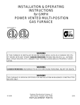
MAXIMUM DIRECT VENT, DUAL PIPE LENGTH (FT.)
M7RL INPUTS
(BTU)
INLET / OUTLET
2” DIAMETER
INLET / OUTLET
3” DIAMETER
45,000 30 60
60,000 30 60
72,000 30 60
NOTES:
1. Subtract2.5ft.foreachadditional2inchlongradiuselbow,subtract
5ftforeachadditional2”shortradiiouselbow,subtract3.5ft.foreach
additional3inchlongradiuselbow,and7ft.foreachadditional3
inchshortradiuselbow.
2. Two45degreeelbowsareequivalenttoone90degreeelbow.
3. Thistableappliesforelevationsfromsealevelto2,000ft.Forhigher
elevations,decreasepipelengthsby8%per1,000ftofaltitude.
Table 2. Vent Pipe Lengths
• In the absence of local codes, the location of any
combustionairinletrelativetoanyventterminalmust
beatleast8inches.Thisincludesinstallationsinvolving
morethanonefurnace.
• Thequalityofoutdoorairmustalsobeconsidered.Be
surethatthecombustionairintakeisnotlocatednear
a source of solvent fumes or other chemicals which
cancausecorrosionofthefurnacecombustionsystem.
(Seepage5forasamplelistofsubstances).
• Routepipingasdirectaspossiblebetweenthefurnace
and the outdoors. Longer vent runs require larger
diameters.Ventpipingmustbeslopedupwards1/4”
perfootinthedirectionfromthefurnacetotheterminal.
This ensures that any condensate ows back to the
condensatedisposalsystem.
• When a 2-pipe system is used, the combustion air
intake and the vent exhaust must be located in the
same atmospheric pressure zone. This means both
pipesmustexitthebuildingthroughthesameportion
ofexteriorwallorroofasshowninFigure1,Figure2
&Figure4(page9)andFigure29(page38).
• Pipingmustbemechanicallysupportedsothatitsweight
doesnotbearonthefurnace.Pipesupportsmustbe
installedaminimumofeveryvefeetalongtheventrunto
ensurenodisplacementafterinstallation.Supportsmay
beatshorterintervalsifnecessarytoensurethatthere
arenosaggingsectionsthatcantrapcondensate.Itis
recommendedtoinstallcouplings(Figure29)alongthe
ventpipe,oneithersideoftheexteriorwall.Couplings
mayberequiredbylocalcode.
• Ifbreakableconnectionsarerequiredinthecombustion
airinletpipe(ifpresent)andexhaustventpiping,then
straight neoprene couplings for 3” piping with hose
clampscanbeused.Thesecouplingscanbeordered
through your local furnace distributor. To install a
coupling:
1. Slidetherubbercouplingovertheendofthepipe
thatisattachedtothefurnaceandsecureitwithone
ofthehoseclamps.
2. Slidetheotherendoftherubbercouplingontothe
otherpipefromthevent.
3. Securethecouplingwiththesecondhoseclamp,
ensuringthattheconnectionistightandleakfree.
OutdoorTerminations-HorizontalVenting
• Ventandcombustionairintaketerminationsshallbe
installedasshown inFigure1,Figure 2,Figure3,&
Figure4andinaccordancewiththeseinstructions:
• Ventterminationclearancesmustbeconsistentwiththe
NFGC,ANSI2223.1/NFPA54and/ortheCSAB149.1,
NaturalGasandPropaneInstallationCode.Table14,
(page37)liststhenecessarydistancesfromthevent
terminationtowindowsandbuildingairintakes.
• Vent and combustion air intake terminations must
be located to ensure proper furnace operation and
conformance to applicable codes. A vent terminal
mustbelocatedat least3feetaboveanyforcedair
inletlocatedwithin10feet.Thisdoesnotapplytothe
combustionairinletofadirectvent(twopipe)appliance.
InCanada,CSAB149.1takesprecedenceoverthese
instructions.SeeTable14.
Condensingfurnacecombustionproductshaveverylittle
buoyancy,soTable2istobeusedwithoutconsideration
ofanyverticalriseinthepiping.
VentPipeMaterial
Ventandcombustionairpipeandttingsmustbeone
ofthefollowingmaterialsinthelistandmustconformto
theindicatedANSI/ASTMstandards.
MATERIALS STANDARDS
SCHEDULE40PVC................................................... D1785
PVC-DWV.................................................................. D2665
SDR-21&SDR-26..................................................... D2241
ABS-DWV.................................................................. D2661
SCHEDULE40ABS....................................................F628
FOAM/CELLULARCOREPVC.................................F891
*POLYPRO
®
BYDURAVENT................................. ULC-S636
*WhenusingPolyPro
®
,allventingandttingsmustbefromthesame
manufacturerwithnointerchangingofothermaterials.Refertospecic
instructionssuppliedwiththePolyProventkits.
WhenjoiningPVCtoPVC,usecementthatconformsto
ASTMstandardD2564.PVCprimermustmeetstandard
ASTMF656.WhenjoiningABStoABS,usecementthat
conformstoASTMstandardD2235.WhenjoiningPVCto
ABS,usecementasspeciedinprocedurefromASTM
standardD3138
In Canada, all plastic vent pipes and ttings including
anycement,cleaners,orprimersmustbecertiedasa
systemtoULCS636.Howeverthisrequirementdoesnot
applytothenishangesorpipinginternaltothefurnace.
VentPipeInstallation
CAUTION:
Combustion air must not be drawn from a
corrosive atmosphere.
Thisfurnacehasbeencertiedforinstallationwithzero
clearancebetweenventpipingandcombustiblesurfaces.
However,itisgoodpracticetoallowspaceforconvenience
ininstallationandservice.
9
• Allminimumclearances(Figure2)mustbemaintained
toprotectbuildingmaterialsfromdegradationbyue
gases.
• Foroptimalperformance,ventthefurnacethrougha
wallthatexperiencestheleastexposuretowinterwinds.
• The vent termination shall be located at least 3 ft.
horizontallyfromanyelectricmeter,gasmeter,regulator
andanyreliefequipment.ThesedistancesapplyONLY
to U.S. installations. In Canada, CSA B149.1 takes
precedenceovertheseinstructions.
• Donot install the vent terminal such that exhaust is
directed into window wells, stairwells, under decks
orintoalcovesorsimilarrecessedareas,anddonot
terminateaboveanypublicwalkways.
• Ifventinghorizontally,sidewallventkitsareavailable
accordingtothepipediametersizeoftheinstallation.
For3inchpipe,usekit#904347.Faceplatekit#902375
isalsoavailablefor3inchhorizontalventing.Please
follow the instructions provided with the kits.
• Concentricventterminationkitsareavailableforuse
withthesefurnaces.For3inchpipeusekit#904953.
Please follow the instructions provided with the kit.
• Whentheventpipemustexitanexteriorwallcloseto
thegradeorexpectedsnowlevelwhereitisnotpossible
toobtainclearancesshowninFigure1,arisermaybe
providedasshowninFigure3.Insulationisrequired
topreventfreezingofthissectionofpipe.SeeTable
3,(page10)forventfreezingprotection.
OutdoorTerminations-VerticalVenting
Terminationspacingrequirementsfromtheroofandfrom
eachotherareshowninFigure4.Theroofpenetration
mustbeproperlyashedandwaterproofedwithaplumbing
roofbootorequivalentashing.Ventandcombustionair
pipingmaybeinstalledinanexistingchimneywhichis
notinuseprovidedthat:
• Boththeexhaustventandairintakerunthelengthof
thechimney.
• Thetopofthechimneyissealedandweatherproofed.
• The termination clearances shown in Figure 4 are
maintained.
• Noothergasredorfuel-burningequipmentisvented
throughthechimney.
12” min. to maximum
expected snow level
(both pipes)
90° Elbow
Exhaust vent
option B
Exhaust vent
option A
Mounting kit faceplate
secured to wall with screws
(both pipes)
Combustion
air inlet
Exhaust vent
option C
18” Min.
36” Max.
8” Min.
36” Max.
(all positions)
Figure 1. Inlet&ExhaustPipeClearances
Figure 3. Alternate Horizontal Vent Installation
Support
NOTE: Vent Configuration to Provide
12" Minimum height above Snow Level.
1/2"
Armaflex
Insulation or
Equivalent
(if required)
12" Above
Maximum
Expected
Snow Level
19" Max.
(See Note)
Outside
Wall
Note 2
Mechanical draft
vent terminal
Direct vent
terminal
50,000 Btuh
or less
Forced air inlet
Direct vent
terminal - more
than 50,000 Btuh
Mechanical
draft vent
terminal
Mechanical
draft vent
terminal
Less
than
10 ft.
3 ft.
NOTES:
1. All dimensions shown are
minimum requirements.
2. Exterior vent terminations must
be located at least 12” above the
maximum expected snow level.
Note 2
4 ft
4 ft
12 in.
12 in.
9 in.
Note 2
Figure 2. Vent Locations
Figure 4. Vertical Vent Termination
Combustion Air
Exhaust Vent
12” Above Maximum
Expected Snow Level
(Both pipes)
Elbows on the combustion air
inlet must be positioned pointing
away from the exhaust vent.
8" Min.
36" Max.
Plumbing Vent Roof Boot
(Both Pipes)
10
ExistingInstallations
Whenanexistingfurnaceisremovedfromaventsystem
servingotherappliances,theexistingventsystemmay
notbesizedproperlytoventtheremainingappliances
(example: water heater). An improperly sized venting
systemcanresultintheformationofcondensate,leakage,
orspillage.Theexistingventsystemshouldbechecked
tomakesureitisincompliancewithNFGCandmustbe
broughtintocompliancebeforeinstallingthefurnace.
NOTE: Ifreplacinganexistingfurnace,itispossibleyou
willencounteranexistingplasticventingsystemthatis
subjecttoaConsumerProductSafetyCommissionrecall.
ThepipesinvolvedintherecallareHighTemperature
PlasticVent(HTPV).If your venting system contains
these pipesDO NOT reuse this venting system!This
recall does not apply to other plastic vent pipes, such
aswhitePVCorCPVC.CheckfordetailsontheCPSC
websiteorcalltheirtoll-freenumber(800)758-3688.
Ventilaire III or IV Air Quality Package
TheVentilaireairqualityaccessorypackagesareavailable
tomeettheventilationrequirementsasoutlinedinH.U.D.
StandardPart3280.103(b)(2).Thesepackagesintroduce
outdoorairintothe livingspaceduringfurnaceblower
operation.TheVentilAireIValsoservestoexhaustmoist
and/orhotairfromtheatticspace.SeeFigure5fortypical
installation.Completeinstallationinstructionsaresupplied
witheachairqualitypackage.
VentilAire III
VentilAire IV
Figure 5. VentilAire III & IV
VentFreezingProtection
CAUTION:
Whentheventpipeisexposedtotemperatures
below freezing (i.e., when it passes through
unheated spaces, chimneys, etc.) the pipe
must be insulated with 1/2 inch thick sponge
rubber insulation, Armaex-type insulation or
equivalent. Insulating pipe is important to avoid
condensate icing.
• Table3liststhemaximumlengthofuepipethatcan
travelthroughanunconditionedspaceoranexterior
space. The total vent length must not exceed the
lengthsnotedinthetable.ForCanadianinstallations,
pleaserefertotheCanadianInstallationCode(CAN/
CGA-B149.1or2)and/orlocalcodes.
• Forextremelycoldclimatesorforconditionsofshort
furnace cycles (i.e. set back thermostat conditions)
thelast18inchesofventpipecanbereduced.Itis
acceptabletoreducefrom3”to2-1/2”or,3”to2”ifthe
totalventlengthisatleast15feetinlength,andthe
ventlengthiswithintheparametersspeciedinTable
2, (page 8). The restriction should be counted as 3
equivalentfeet.Smallerventpipesarelesssusceptible
tofreezing,butmustnotbeexcessivelyrestrictive.
• To prevent debris or creatures from entering the
combustionsystem,aprotectivescreenmaybeinstalled
overthecombustionairintakeopening.Thescreens
holesizemustbelargeenoughtopreventairrestriction.
WINTER
DESIGN
TEMPERATURE
MAXIMUM FLUE PIPE
LENGTH (FEET) IN
UNCONDITIONED & EXTERIOR SPACES
WITHOUT
INSULATION
WITH
INSULATION*
20 45 70
0 20 70
-20 10 60
*NOTE: Insulation thickness greater than 3/8 inch, based on an
Rvalueof3.5(ftxFxhr)/(BTUxin.)
Table 3. Vent Protection
11
CIRCULATING AIR REQUIREMENTS
WARNING:
Do not allow combustion products to enter the
circulating air supply. Failure to prevent the
circulation of combustion products into the
living space can create potentially hazardous
conditionsincludingcarbonmonoxidepoisoning
that could result in personal injury or death.
All supply ducts must be secured to the furnace
with sheet metal screws and adequately sealed.
When supply air is provided through the bottom
of the unit, the joint between the furnace and the
plenum must be air tight.
The surface that the furnace is mounted on must
provide sound physical support of the furnace
with no gaps, cracks or sagging between the
furnace and the floor or platform.
Supply air ducts must not be connected to any
other heat producing device such as a fireplace
insert,stove,etc.Thismayresultinre,explosion,
carbonmonoxidepoisoning,personalinjury,or
property damage.
Plenums & Air Ducts
Thisunitisdesignedonlyforusewithabottomsupply
duct and must be installed in accordance with the
standards of the National Fire Protection Association
Standard for Installation of Air Conditioning Systems
(NFPA90A),StandardforInstallationofResidenceType
WarmAirHeatingandAirConditioningSystems(NFPA
90B),andallapplicablelocalcodes.NFPApublications
are available by writing to: National Fire Protection
Association,BatterymarchPark,Quincy,ME02269orgoto
www.NFPA.orgontheweb.
• Designtheairductsaccordingtomethodsdescribedby
theAirConditioningContractorsofAmerica(ACCA).
• Airductsmustbealuminum,tinplate,galvanizedsheet
steel,orotherapprovedmaterialsforoutletorreturn
air ducts. Snap-Lock or Pittsburgh-Lock seams are
preferred.Allothertypesofseamsmustbemadetight
topreventleakage.
• Itis good practice to seal all connections and joints
with industrial grade sealing tape or liquid sealant.
Requirements for sealing ducts vary from region to
region.Consultwithlocalcodesforrequirementsspecic
toyourarea.
• Gaspipingmustnotruninorthroughanyoftheairduct
system.
Hollow spaces used as ducts or plenums for
environmentalairmaycontainmineral-insulatedmetal
sheathedcable,aluminumsheathedcable,electrical
metallic tubing, rigid metal conduit, exible metal
conduit(nottoexceed4ft),ormetal-cladcables.Wiring
materials,xtures,aretobesuitablefortheexpected
ambienttemperaturestowhichtheywillbesubjected.
Wiringmaterialslocatedinthereturnductsystemshall
conform to Articles 300-22 of the National Electrical
Code(NFPA-70).
• All duct work passing through unconditioned space
must be properly insulated to minimize duct losses
andpreventcondensation.Useinsulationwithanouter
vaporbarrier.Refertolocalcodesforinsulationmaterial
requirements
• Airconditioningsystemsmayrequiremoreductregister
andopenlouverareatoobtainnecessaryairow.Use
NORDYNE’s certiduct program to determine proper
ductsizesforairconditioning.
• Noncombustiblepanshavingoneinchupturnedanges
are located beneath openings in a oor return duct
system.
Supply Air Connections
• Forproperairdistribution,thesupplyductsystemmust
be designed so that the static pressure measured
externaltothefurnacedoesnotexceedthelistedstatic
pressureshownonthefurnaceratingplate.Thesupply
airmustbedeliveredtotheheatedspacebyduct(s)
securedtothefurnacecasing,runningfulllengthand
withoutinterruption.
• Ductsystemmustbedesignedsothatnosupplyregisters
arelocatedinductsystemdirectlybelowthefurnace.
• Location, size, and number of registers should be
selectedonthebasisofbestairdistributionandoor
planofthehome.Threetypicaldistributionsystemsare
showninFigure6.
A Single trunk duct
B
Dual trunk duct
w/crossover connector
C
Transition duct
w/branches
Figure 6. Typical Supply Duct Systems
Return Air Connections
• M7furnaceswithmodelnumbersendinginAWorBW
arefactoryconguredforthereturnairtoowthrough
the front louvered door. The return air may also be
attachedtoeithersideofthefurnacecabinetusinga
eldinstalledkit(PN904003).Thelocationandsize
ofthesideandtopreturnairconnectionsareshownin
Figure 24 (page 30) & Figure 25 (page 31). The
ltersizeforthesidereturnairis20”x20”x1”.
• Model numbers ending in AWT & BWT are factory
congured for the return air to enter the top of the
furnace.SeeFigure26(page32)&Figure27(page
33).
12
NOTE:Fortopreturninstallations,anexternalorin-
wallltermountcanbeused.Thefactoryinstalledlter
shouldberemovedandthereturnductshouldbesized
toprovideadequateairow.
• For oor return systems, the manufactured housing
manufacturerorinstallershallafxaprominentmarking
onorneartheappliancewhereitiseasilyreadwhen
theclosetdoorisopen.Themarkingshallread:
CAUTION, HAZARD OF ASPHYXIATION. DO NOT
COVER OR RESTRICT FLOOR RETURN AIR
OPENING.
• Returnairopeningsshouldnotbelocatedtodrawair
directlyfromabathroom.
• Materialslocatedinthereturnductsystemshallhave
aamespreadclassicationof200orless.
• Thetotalfreeareaoftheopeningsintheoororthe
ceilingregistersservingthereturnairductsystemmust
notbenotlessthan352in
2
(2,270cm
2
).Atleastone
registershouldbelocatedwhereitisnotlikelytobe
coveredbycarpeting,boxesandotherobjects.
Closet & Alcove Installations
WARNING:
Failure to comply with the the following
instructionsmayresultinre,asphyxiationor
carbonmonoxidepoisoning.
For proper air circulation, closet installations require
a return air grill installed in the door or side wall that
exchangeswiththelivingareaofthehome.Apartially
louvereddoormayalsobeusedacrosstheopening.Grilles
placedinasidewallrequirea6”clearancefromthewall
tothefurnace sothattheairmayenterthefrontgrille
ofthefurnace.Allreturnairsystems,includingtheoor
andceilingsystems,mustmeetthefollowingconditions:
• Thereturnairopening,regardlessofitslocationinthe
closet,mustnotbesmallerthansizespeciedonunit
datalabel.Iflocatedintheoor,theopeningmustbe
provided with a means of preventing its inadvertent
closurebyatobject(s)placedovertheopening.
• Thecross-sectionalareaofthereturnductsystem(in
oororceiling)leadingintotheclosetmustnotbeless
than235in
2
(1,516cm
2
).
CAUTION:
HAZARD OF ASPHYXIATION: Negative pressure
inside the closet, with closet door closed and
the furnace blower operating on high speed,
shall be no more negative than minus 0.05 inch
water column.
• Testthenegativepressureintheclosetwiththeair-
circulatingfanoperatingathighspeedandthecloset
closed.Thenegativepressureintheclosetmustnot
belessthanminus0.05incheswatercolumnwiththe
closetdoorclosedandthefanoperatingathighspeed.
Thenegativepressureistobenomorenegativethan
minus0.05”watercolumnasthisindicatesadirtylter
orarestrictedreturnairsystem.
• Forclosetinstallationwithlessthan6”frontclearance,
but not less than 1”, a louvered door must be used
havingaminimum250in
2
(1,613cm
2
)freeareaopening
directlyinlinewithopeningsinthefurnacedoor.For1”
clearancefromfurnace,useafullylouvereddoorwith
atleast400in
2
(2,580cm
2
)offreeairowarea.
Furnace Filter
WARNING:
Never operate the furnace without a filter in place.
Accumulating dust in the return air can build
up on internal components, resulting in loss of
efficiency, equipment damage, and possible fire.
• M7RLfurnaceswithAWorBWsufxesaresupplied
withasinglereusableairlterwhenshippedfromthe
factory.Accessingthelterdoesnotrequiretoolsand
canbeeasilyremovedfromtheinsideoftheaccess
door.Thelterissecuredtothedoorwitharetaining
bracket.
• M7RLfurnaceswithAWT&BWTsufxesareshipped
with a non-reusable single 18”x18”x1” air lter from
thefactory.Accessingthelterdoesnotrequiretools
and can be easily removed from inside the blower
compartment. The lter is secured with a U-shaped
retainingbracket.Itisrecommendedthatthelterbe
cleanedorreplacedmonthly.Newlybuiltorrecently
renovatedhomesmayrequiremorefrequentchanging
untiltheconstructiondusthasminimized.
1. Slide the standard 18”x18”x1” lter (P/N 669779)
into the space bewteen the combustion air pipe
andtheblowerassembly.SeeFigure7(page13).
NOTE: Make sure the airowarrowsonthelter
pointtowardstheblowerassembly.
2. Pushtheltertotherearofthefurnacecabinetand
angleitupovertheblower.Makesurethelteris
pushedbackasfaraspossible.
3. Positionthelterretainerunderthelterandinsert
thesteppedendsintothe0.25holesintherearof
thefurnace. NOTE:The steppedends should be
facingupwardsintheholes.
4. Evenlyalignthelterovertheopeninginthetopof
thefurnacecabinetandpositiontheotherendof
lterretainerupovertheangeinthefurnace’stop
panel. NOTE:To properly secure the lter, make
surethelterretainerisproperlypositionedinthe
toppanelofthefurnace.Thereshouldbenovisible
airgaps.Theretainermayslideleftorrightslightly,
butmustnothaveanymovementbetweenthefront
andrear.SeeFigure7.
13
• Replacementltersareavailableatmostlocalretailers.
Inspectltersfrequentlyandreplacewhennecessary
withlterofsamedimensionalsize.Filtersdesignedto
removesmallerparticlessuchaspollen,mayrequire
additionalmaintenance.
Dampers
Anautomatedshutoffdamperisrequiredwhenthehome
is air conditioned by a self-contained unit. A damper
is required to prevent chilled air from owing over the
furnaceheatexchanger.Thisdamperisdesignedtot
inthefeederductcavity,directlyunderthefurnace.For
properinstallation,refertotheinstructionsprovidedwith
thedamper.Seereplacementpartslistprovidedonline.
Acoustical Treatments
Damping ducts, exible vibration isolators, or pleated
media-styleltersonthereturn airinletofthefurnace
maybeusedtoreducethetransmissionofequipment
noiseeminatingfromthefurnace.Thesetreatmentscan
produceaquieterinstallation,particularlyintheheated
space.However,theycanincreasethepressuredropin
theductsystem.Caremustbetakentomaintaintheproper
maximumpressureriseacrossthefurnace,temperature
riseandowrate.Thismaymeanincreasingtheductsize
and/orreducingtheblowerspeed.Thesetreatmentsmust
beconstructedandinstalledinaccordancewithNFPAand
SMACNAconstructionstandards.Consultwithlocalcodes
forspecialrequirements.Forbestsoundperformance,
install all the needed gaskets and grommets around
penetrationsintothefurnace,suchasforelectricalwiring.
Combustion Air Pipe
Blower
Assembly
Insert filter between
blower assembly &
combustion air pipe
Blower
Assembly
Angle the filter into place
above the blower assembly
Combustion Air Pipe
Filter
Blower
Assembly
Combustion Air Pipe
Align the filter
over the opening and
secure with filter retainer
Filter
Blower
Assembly
Figure 7. Filter Installation
14
FURNACE INSTALLATION
NOTE: TheseInstallationproceduresaresuggestedfor
typical furnace installations. Since each installation is
different, the sequence of instructions may differ from
theactualinstallation.OnlyqualiedHVACtechnicians
shouldinstallthisfurnace.
Theinstaller must be familiar withand comply with all
codes and regulations applicable to the installation of
these heating appliances and related equipment. In
theabsenceoflocal codes,theinstallationmustbein
accordancewiththecurrentprovisionsofoneormoreof
thefollowingstandards.
• FederalManufacturedHome Constructions &Safety
Standard(H.U.D.Title24,Part3280.707[a][2])
• AmericanNationalStandard(ANSI-119.2/NFPA-501C)
forallrecreationalvehicleinstallations.
• AmericanNationalStandard(ANSI-Z223.1/NFPA-54)
and/orCAN/CSAB149forallgas-redfurnacemodels.
• American National Standard (ANSI-Z95.1/NFPA-31)
and/orCSAB139foralloil-redfurnacemodels.
• American National Standard (NFPA-70) and/or CSA
22.1 Canadian Electric Code Part 1 for all electrical
eldwiring.
• UnitshavebeenresearchedunderstandardsUL307A
&B,UL727-1999,ANSIZ21.47b/CSA2.3b-2008,and
CSAB140.10.
About The Furnace
TheM7RLfurnaceisdesignedonlyforindoorinstallations
and can be readily connected to the high static duct
systemofahome.Unitsareapprovedforsingle/multistory
residentialormobile/modular/manufacturedstructuresin
freestanding/closet/alcovedownowonlycongurations.
This appliance will provide many years of safe and
dependable comfort, providing it is properly installed
andmaintained.Abuse,improperuse,and/orimproper
maintenancecanshortenthelifeoftheapplianceand
createunsafehazards.Pleasereadallinstructionsbefore
installingtheunit.
Approved installation, operation, and maintenance of
this appliance must be in accordance with the listed
specicationscontainedintheseinstructionsandother
documentssuppliedwiththefurnaceand/oroptionalair
conditioningequipment.Unlessitisnoteddifferentlyinthis
manual,onlyusefactoryauthorizedkitsandaccessorieson
thisappliance.Refertolocalauthoritieshavingjurisdiction
forfurtherinformation.
Before You Install this Furnace
This equipment is securely packaged at the time of
shipmentanduponarrivalshouldbecarefullyinspected
fordamagepriortoinstallingtheequipmentatthejob
site.Claimsfordamage(apparentorconcealed)should
beledimmediatelywiththecarrier.
Checktheelectricalsupplyandverifythepowersupply
isadequateforunitoperation.Thesystemmustbewired
andprovidedwithcircuitprotectioninaccordancewith
localbuildingcodes.Ifthereisanyquestionconcerning
thepowersupply,contactthelocalpowercompany.
Verify the air delivery of the furnace is adequate to
handlethestaticpressuredropofthecoil,lter,and
ductwork.
Locating the Unit
• Thedimensionsoftheroomoralcovemustbeableto
accommodatetheoverallsizeoftheunitandrequired
clearancestocombustiblematerialslistedinTable1
(page5).Accessforpositioningandservicingmustalso
be considered when locating the unit. To determine
the required clearances needed for installation and
combustible materials, refer to Figure 24 (page 30),
Figure25(page31),Figure26(page32)andFigure
27(page33)foroveralldimensions.
• Thefurnacemustbeinstalledonasolidsurfaceandmust
belevelfront-to-backandside-to-sideatinstallation.The
surfacethatthefurnaceismountedonmustprovide
soundphysicalsupportoftheunit.
• Thefurnaceshouldbeinstalledasclosetothecenterof
theairdistributionsystemaspossibleandattachedto
aproperlyinstalledductsystem.Do not use the back
of the furnace for return air. See pages 11 - 12
forcirculatingrequirements.
• The furnace must be installed so that all electrical
componentsareprotectedfromwater.
• TheplenumattachedtotheA/Ccoilboxandductwork
within 3 ft. of the furnace must be installed so that
surfacesareatleast1/4”fromcombustibleconstruction.
• Wheninstalledinaresidentialgarage,thefurnacemust
be positioned so the burners and the source of the
ignitionarelocatednolessthan18inchesabovethe
oorandprotectedfromphysicaldamagebyvehicles.
• This furnace is certied for use on wood ooring or
supports,butmustnotbeinstalleddirectlyoncarpeting,
tile,oranycombustiblematerialotherthanwoodooring.
NOTE:Thefurnacemaybeinstalledoncombustible
ooringwheninstalledonaductconnector(Figure8).
Thisfactorysuppliedaccessorymustbeinstalledinthe
oorcavityandattachedtothesupplyairductbefore
thedownowfurnaceisinstalled.
• The furnace must be installed upstream from a
refrigerationsystem.
NOTES:
With reducer installed: Opening to duct is 10-1/4” x 13-1/4”.
With reducer removed: Opening to duct is 13-1/4” x 13-1/4”.
REDUCER
(See Notes)
FELT-SEAL
SPACERS
DUCT CONNECTOR TABS
FIBERGLASS
INSULATION
Figure 8. Duct Connector
15
14 1/2”
14 1/2”
Floor Cut-Out for
Duct Connector
FURNACE CABINET OUTLINE
Optional floor cutouts for gas,
condensate, or AC linesets
(3 1/2 x 1 1/2 - 2 places)
21 5/8
TYP.
1/2 TYP.
REAR WALL OF CLOSET OR ALCOVE
2 1/4
16 3/4
Furnace Door
1 1/2 TYP.
C
L
20"
2 3/4
Figure 9. Floor Cutout Dimensions
CEILING CUT-OUTS FOR
VENT & COMBUSTION AIR
C
L
20"
23 3/4"
REAR WALL OF CLOSET OR ALCOVE
FURNACE
OUTER
DOOR
FURNACE OUTLINE
21 7/8
2 1/2
2 3/4
C
L
C
L
C
L
COMBUSTION
AIR INLET
EXHAUST
VENT
Figure 10. Ceiling Cut-Out Dimensions
“X”
FLOOR OPENING
FLOOR
CAVITY
SUPPLY AIR DUCT
IF FLOOR CAVITY
(“X”) IS:
DUCT CONNECTOR
TYPE & PART NUMBER
FINGER TAB SCREW DOWN
7/8”(22) 901987A 904008
2”(51) 901988A 904009
4-1/4”(108) 901989A 904010
6-1/4”(159) 901990A 904011
8-1/4”(210) 901991A 904012
10-1/4”(260) 901992A 904013
12-1/4”(311) 901993A 904014
NOTE:DimensionsshownasInches(Millimeter)
Table 4. Duct Connector Sizes
Locating&CuttingFloorOpenings
IMPORTANT NOTE:
Cut-outs in the floor, must be carefully located to
avoid misalignment of the furnace.
Tolocatestandardducts,seeFigure9.Forroundducts,
seeFigure10.
1.Measure from the rear wall or alcove and mark the
centerlineofthecut-outontheoor.Usingthecenterline
asastartingpoint,drawtherestoftheductcut-outto
thedimensionsshowninFigure9.
2.Cutouttheooropeningtowithin1”oftheactualcutout
drawn.
3.Measurefromthetopoftheoordowntothetopofthe
supplyairducttoobtainthedepthoftheoorcavity.
NOTE:Thedepthoftheoorcavityshownas“X”in
Table4willdeterminethecorrectductconnector.
4.Determinewhichductconnectortousefromthetable.
5.Measureanddrillgasholeandcutoutforcoolingcoil
(ifapplicable).SeeFigure9orFigure10.
Locating&CuttingCeilingOpenings
IMPORTANT NOTE:
Cut-outs in the ceiling and roof must be carefully
located to avoid misalignment of the furnace,
combustion air piping, and vent piping. See Figure 10.
1.Measure from the rear wall or alcove and mark the
centerlinesofbothcut-outsintheceiling.
2.Usingthecenterlinesasastartingpoint,drawtherest
ofthecut-outstothedimensionsshowninFigure10.
3.Cutouttheceilingopenings.
Installing Finger Tabbed Duct Connectors
Thestandardductconnectorisdesignedforuseonducts
12”inwidth.Howeverductsnarrowerthan12”maynot
allowsufcientclearancesforthistypeofinstallation.For
analternateinstallationmethod,seepage16.
1.Center the duct connector in the oor opening with
bottomtabsrestingontopofthesupplyairduct.
2.Markthecut-outareaonthesupplyairductbytracing
aroundtheconnectortabsoftheductconnector.
3.Remove the ductconnectorandcutoutthemarked
areaofthesupplyairduct1/16”largertheactualcutout
drawn.SeeFigure11(page16).
4.Installtheductconnectorbackintheooropeningwith
thebottomtabsextendingintothesupplyairduct.
5.Installthemountingplate(Figure11)undertheback
sideoftheductconnector.Alignthescrewholesinboth
components.
6.Securetheductconnectorandthemountingplateto
thewoodoorwithappropriatesizescrews.
7.Bend the connector tabs on the bottom of the duct
connector upwards and as tight as possible against
thesupplyairduct.SeeFigure11.
8.Sealallconnectionswithindustrialgradesealingtape
or liquid sealant. NOTE: Requirements for sealing
ductworkvaryfromregiontoregion.Consultwithlocal
codesforrequirementsspecictoyourarea.
16
Tabs slide into slots
in back of furnace
Mounting
Plate
Duct
Connector
Supply
Air Duct
Hole for
Gas Line
Wood Floor
Connector
Tabs
Duct Connector
Supply
Air Duct
Bend tabs tightly
against supply air duct
Figure 11. Finger Tabbed Duct Connector
NarrowDuctAttachment-Option1
These alternate attachment methods may be used to
installafurnaceductconnectortonarrowmetalductwork
ifinsufcientclearancespreventthebendingoftheduct
connectortabsatthesideoftheduct.
1.SelectOptionAorOptionBinFigure12andcutthe
topofthesupplyairduct.Removemetalapsfromthe
duct(shadedarea)ifOptionAisselected.
2.Foldtheductapsuptoformanopeningfortheduct
connector(appliestoOptionsAorB).
3.Installtheductconnectorwiththebottomtabsextending
intothesupplyairduct.
4.Bend the tabs on the bottom of the duct connector
upwardsandastightaspossibleagainsttheremoved
endsofthesupplyairduct.
5.Form the duct aps up against the side of the duct
connectorastightaspossible.SeeFigure12.
6.Securetheductconnectorapstothesupplyairduct
withstaples (3 minimum) or ifa 2x block/joist is not
provided,usesheetmetalscrews(2minimum).
NOTE:Theductconnectortabsmaybeattached to
theairductwithsheetmetalscrewsorothersuitable
fastenersaslongastheductconnectorandtheairduct
aresecurelyattached.
7.Sealallconnectionswithindustrialgradesealingtape
orliquidsealant.
NOTE: Requirements for sealing ductwork vary
from region to region. Consult with local codes for
requirementsspecictoyourarea.
NarrowDuctAttachment-Option2
Thesalternateattachmentmethodsmaybeusedtoinstall
a furnace duct connector to narrow metal ductwork if
insufcientclearancespreventthebendingoftheduct
connectortabsatthesideoftheduct.
1.Cutandremovethetopofthesupplyairductasshown
inFigure13.
2.Installtheductconnectorwiththebottomtabsextending
intothesupplyairduct.
3.Bend the tabs on the bottom of the duct connector
upwardsand astightaspossibleagainstthesupply
airduct(Figure13).
4.Securetheductconnectortabstothesupplyairduct
with staples (3 minimum) or sheet metal screws (2
minimum).
Tabs slide into slots
in back of furnace
Mounting
Plate
Screw Down
Duct Connector
Supply
Air Duct
Hole for
Gas Line
Wood Floor
Figure 14. Screw-Down Duct Connector
Figure 12. Narrow Air Ducts - Option 1
Cutting
Option A
Supply
Air Duct
Fold duct flap here
Remove
this Flap
Cut Here
Cut Here
Cut Here
Cut Here
Cut Here
Cut Here
Cut Here
Cut Here
Cut Here
Fold Flap Here
Narrow
Duct
Narrow
Duct
Finger Tabs
Secure Flaps with Staples
or sheet metal screws
Fold duct flaps
into duct
connector
Remove
this Flap
Fold Flap Here
Cutting
Option B
Fold duct flap here
Supply
Air Duct
Narrow
Duct
Finger Tabbed
Duct Connector
Secure finger tabs to
side of air duct with staples
or sheet metal screws
Bend tabs tightly
against supply air duct
Supply Air Duct
Cut out & remove
Figure 13. Narrow Ducts - Option 2
17
Figure 15. Round Duct Connector
Tabs slide into slots
in back of furnace
Mounting
Plate
14” Round
Duct Connector
Optional Hole
for Gas Line
Optional Hole
for Gas Line
Installing Screw-Down Duct Connectors
1.Applyabead of caulking, mastic,orotherapproved
sealantaroundbottomsideof1/2”angeandrestrictor
plate(whenapplicable).
2.Locatethescrewdownductconnectorovertheduct
andcarefullyloweritintoplace.
3.Securetheductconnectortotheoorusingathead
screwsornails.NOTE:Makesuretheductconnector
angesstayincontactwiththeduct.
4.Securetheplenumtotheductusingsheetmetalscrews
makingsureatightsealismadebetweentheductand
theductconnector.NOTE:Additionalscrewsmaybe
addedifrequired.
5.Cutawayalongedgeofangeallowingthecenterto
dropintotheduct.NOTE:Removesectionofductwith
caution,asedgeswillbesharp.
Round Duct Connector Installation
1.Installandcentertheductconnectorintheooropening.
2.Installthemountingplate(Figure15)undertheback
sideoftheductconnector.NOTE:Makesurethescrew
holesarealignedinbothcomponents.
3.Usingappropriatesizescrews,securetheductconnector
andthemountingplatetothewoodoor.
4.Connecttheroundsupplyducttotheundersideofthe
duct connector and secure them with eld supplied
sheetmetalscrewsorappropriateclamps.
5.Sealallconnectionswithindustrialgradesealingtape
orliquidsealantasrequired.
Requirements for sealing ductwork vary from region
to region. Consult with local codes for requirements
specific to your area.
Installing the Furnace
Sidesandbackofthefurnacemaybeenclosedbywall
framingsuchasinaclosetoralcove.Thedimensions
oftheroomoralcovemustbeabletoaccommodatethe
overallsizeofthefurnaceandtheinstallationclearances
outlinedonpage5andFigure1,Figure2,Figure3,&
Figure 4 (page 9). The furnace shall be appropriately
connectedtothesupplyandreturnairdistributionsystem
asshowninFigure24(page30),Figure25(page31),
Figure26(page32),andFigure27(page33).
1.Remove furnace outer door(s) and bottom fuel line
knockout.
2.Placefurnaceontoductconnectorandcenterwithoor
opening.
3.Slideontomountingplate.(Bottomrearslotsonfurnace
shouldengagewithmountingplatetabs.)
4.Securefrontwithone(1)fastenerateachcorner(Figures
15or16).
NOTE:Additionalfastenersmaybeusedatrear,sides
orthroughdoorframe,asdesired,tosecurefurnaceto
closetoralcoveframing.
Condensate Drainage
WARNING:
The condensate produced by the furnace must
be drained. Do not connect a water supply to the
drainage hose of the furnace.
CAUTION:
Do not install additional traps in the condensate
drain.
If the furnace is installed in an area where
temperatures fall below freezing, special precautions
must be made for insulating condensate drain lines
that drain to the outdoors. If condensate freezes
in the lines, this will cause improper operation or
damage to the furnace. It is recommended that
all drain lines on the outside of the residence be
wrapped with an industry approved insulation or
material allowed by local code.
• Beforeroutingthedraintubeoutofthefurnace,loosen
thetubeclampandturnthetubesothepreset90°turn
facestheintendeddirectionofexitfromthecabinet.Do
notroutethedraintubewithoutrotatingthetuberst.
Thiswillkink the tube andpreventcondensate from
draining.
• Careshouldbetakentoroutethedrainlineawayfrom
theburnerbox.Drainlinesrestingontheburnerbox
canbecomekinkedorcollapsedduetotheheatfrom
theburnerbox.
• Thecondensatedrainmayexitthroughtheleftorright
slotsinthebottomofthefurnace(Figure17).Makesure
theexibledrainhoseisnotkinked.
18
Figure 16. Cabinet Furnace on Supply Air Duct
J-Trap
Drain Pipe Routed
thru Slot in Cabinet
To External Drain
Inline Drain
Assembly
Collector
Box Drain
Collector
Box Drain
Figure 17. Condensate Drainage
GAS SUPPLY & PIPING
• Thecondensateshoulddrainfromtheplasticcollector
box as droplets or a small stream. If you notice the
furnacehasoperatedformorethan5minuteswithout
drainingorthestatuslightsonthecontrolboardindicate
an open pressure switch as listed in Table 7, (page
29),followthestepsbelow.
1. Remove the collector box soft tube (Figure 17) and
verify the exit from the collector box is clear of any
debrisorobstructions.
2.Replacethistubeandverifythettotheheaderspout
is air tight. Air will be drawn into the header if this
connectionisnottight.
3.Checkothertubeconnectionsalongthedrainsystem.
Verifythatallareairtight.
FIRE OR EXPLOSION HAZARD
•Failuretofollowsafetywarningsexactlycould
result in serious injury or property damage.
•Installationandservicemustbeperformed
by a qualified installer, service agency or the
gas supplier.
Do not store or use gasoline or other
flammable vapors and liquids in the vicinity
of this or any other appliance.
WHAT TO DO IF YOU SMELL GAS
•Donottrytolightanyappliance.
•Donottouchanyelectricalswitch;donot
use any phone in your building.
•Leavethebuildingimmediately.
•Immediately call your gassupplier from a
neighbor’s phone. Follow the gas supplier’s
instructions.
•Ifyoucannotreachyourgassupplier,call
the fire department.
WARNING:
RISQUE D’INCENDIE OU D’ EXPLOSION
Le non-respect des avertissements de
sécurité pourrait entraîner des blessures
graves,lamortoudesdommagesmatériels.
L’installation et l’entretien doivent être
effectués par un installateur qualié, un
organisme de service ou le fournisseur de
gazstaller, service agency or the gas supplier.
•Nepasentreposerniutiliserdel’essenceni
d’autres vapeurs ou liquides inflammables
dans le voisinage de cet appareil, ni de tout
autre appareil.
QUE FAIRE S’IL Y A UNE ODEUR DE GAZ
•Nepastenterd’allumeraucunappareil.
•Netoucheràaucuninterrupteurélectrique;
n’utiliseraucuntéléphonedanslebâtiment.
•Évacuerl’immeubleimmédiatement.
•Appeler immédiatement le fournisseur de
gazenemployantletéléphoned’unvoisin.
Respecter à la lettre les instructions du
fournisseur de gaz.
•Sipersonnene répond,appeler leservice
des incendies.
AVERTISSEMENT:
19
• Allgaspipingmustbeinstalledincompliancewith
local codes and utility regulations. In the absence
of local codes, the gas line installation must comply
with the latest edition of the Federal Manufactured
Home Constructions & Safety Standard (H.U.D.
Title 24, Part 3280.707[a][2]), NFGC (ANSI Z223.1)
or (CAN/CGA B149.1 or .2) Installation Codes.
• Somelocalregulationsrequiretheinstallationofa
manual main shut-off valve and ground joint union
externaltothefurnaceasshowninFigure 18. The
shut-off valve should be readily accessible for
service and/or emergency use. Consult the local
utility or gas supplier for additional requirements
regarding placement of the manual main gas shut-
off.
• Gaspipingmustneverruninorthroughairducts,
chimneys, gas vents, or elevator shafts.
• Compoundsusedonthreadedjointsofgaspiping
must be resistant to the actions of LP propane gas.
• Themaingasvalveandmainpowerdisconnectto
the furnace must be properly labeled by the installer
in case emergency shutdown is required.
• Flexiblegasconnectorsarenotrecommendedfor
this type of furnace but may be used if allowed by
local jurisdiction. Only new exible connectors
may be used. Do not use a connector which has
previously serviced another gas appliance.
• Adriplegshouldbeinstalledintheverticalpipe
run to the unit if not entering the furnace through
the floor.
Table9,(page35)listsgasowcapacitiesforstandard
pipesizesasafunctionoflengthintypicalapplications
basedonnominalpressuredropintheline.
Thefurnaceisinstalledwithabottomgasentry.When
connectingthegassupply,provideclearancebetweenthe
gassupplylineandtheentryholeinthefurnacecasing
toavoidunwantednoiseand/ordamagetothefurnace.
TypicalgashookupsareshowninFigure18.
Shut-Off
Valve
Elbows
4
Gas Valve
Gas Valve
Shut-Off
Valve
Elbows
A Cabinet (Short)
B Cabinets
(Tall & Top Return Air Type)
Alternate Fuel
Line Entrance
Alternate Fuel
Line Entrance
Alternate Fuel
Line Entrance
Figure 18. Typical Gas Connections
Leak Check
After the gas piping to the furnace is complete, all
connectionsmustbetestedforgasleaks.Thisincludes
pipe connections at the main gas valve, emergency
shutoffvalveandexiblegasconnectors(ifapplicable).
The soap and water solution can be applied on each
jointorunionusingasmallpaintbrush.Ifanybubblingis
observed,theconnectionisnotsealedadequatelyand
must be retightened. Repeat the tightening and soap
checkprocessuntilbubblingceases.
IMPORTANT NOTE:
When pressure testing gas supply lines at pressures
greater than 1/2 psig (14 inch W.C.), the gas supply
piping system must be disconnected from the furnace
to prevent damage to the gas control valve. If the test
pressure is less than or equal to 1/2 psig (14 inch
W.C.), close the manual shut-off valve.
FIRE OR EXPLOSION HAZARD
Failuretofollowsafetywarningsexactlycould
result in serious injury or property damage.
Never test for gas leaks with an open flame.
Use a commercially available soap solution
made specifically for the detection of leaks
tocheckallconnections.Areorexplosion
may result causing property damage, personal
injury or loss of life.
WARNING:
RISQUE D’INDENDIE OU D’EXPLOSION
Lenon-respectdesavertissementsdesécurité
pourrait d’entraîner des blessures graves, la
mortoudesdommagesmatériels.
Ne jamais utiliser une flamme nue por
vérier la présence des fuites de gaz. Pour
la vérification de tous les joints, utiliser
plutôt une solution savonneuse commerciale
fabriquéespéciquementpurladétectiondes
fuitesdegaz.Unincendieouuneexplosion
peutentraînerdesdommagesmatériels,des
blessures ou la mort.
AVERTISSEMENT:
20
High Altitude Application
High altitude conversion with this furnace depends on
theinstallationaltitudeandtheheatingvalueofthegas.
Installationofthisfurnaceataltitudesabove2,000feet
shallbeinaccordancewithlocalcodes,orintheabsence
oflocalcodes,theNationalFuelGasCode,ANSIZ223.1/
NFPA54orNationalStandardofCanada,NaturalGas&
PropaneInstallationCodeCGAB149.1.Pleaseconsult
yourlocalcodeauthority.
The installer must indicate the furnace has been
converted to high altitude. This may be accomplished
by marking the rating plate with a permanent marker.
WARNING:
The reduction of input rating necessary for high
altitude installation may only be accomplished
with factory supplied orifices. Do not attempt to
drill out orifices in the field. Improperly drilled
orifices may cause fire, explosion, carbon
monoxidepoisoning,personalinjuryordeath.
Thefurnacesareshippedfromthefactorywithorices
andgasregulatorsettingsfornaturalgasoperationatsea
levelaltitudes.At2000feet,theNFGCrequiresthatthis
appliancebederated4%foreach1000feetofaltitude.
Forexample,theinputneedstobereduced8%at2,000
feet,12%at3,000feet,etc.Thisderationisinreference
totheinputrateandgasheatingvalueatsealevel.
Toderatethefurnacerequiresknowingtheheatingvalueof
thegasattheinstallationsite.Heatingvaluesatparticular
jobsitesvaryfortworeasons:
1.Thechemicalmixtureofthegasvariesacrossregions
andisexpressedasthesealevelheatingvalue.
2.Theheatingvaluevariesbyaltitude.Forthisreason,
especially in high altitude areas,the local gas utility
speciestheheatingvalueattheresidence’sgasmeter
asthelocalvalue.
Foraddedexibility,twotableshavebeenprovidedfor
naturalgasinstallationswithhighorlowheatingvalues
at sea level. Table 12 & Table 13, (page 36) contain
themanifoldpressureandoricesizestouseatvarious
altitudes.Table12(HIGH)isfornaturalgasinstallations
withaheatingvalueofmorethan1,000Btupercubicfoot
andTable13(LOW)isforlessthan1,000Btupercubic
foot.Todeterminewhichtabletouse:
1.Consultthelocalutilityfor the local heating valueat
yourinstallationsite.
2.From Table 11, (page 36), nd your local heating
valueassuppliedbytheutilitycompany.Followdown
thecolumnandstopatyouraltitudelevel.
3.IfyoursealevelheatingvalueisHIGH,useTable12
orifit’sLOW,useTable13.Seeexample.
Converting to LP/Propane Gas at Altitudes
between 0 & 10,000 FT.
WARNING:
The furnace was shipped from the factory
equipped to operate on natural gas. Conversion
to LP / Propane gas must be performed by
qualified service personnel using a factory
supplied conversion kit. Failure to use the proper
conversionkitcancausere,explosion,property
damage,carbonmonoxidepoisoning,personal
injury, or death.
ConvertingsinglestagevalvestoLP/Propanerequires
thereplacement of the burnerorices and ipping the
regulatorcaptothesidemarkedLP.Theendfacingup
shouldnowreadLP.SeeFigure19.
InstallationExample
Elevation:.................................................. 5,000feet
Type of Gas:........................................... NaturalGas
Local Heating Value of Gas:.............................. 750
FromTable11,nd750andfollowdownthecolumn,
stopatthe5,000feetrow.Theheatingvaluelistedis
LOW.Table13willbeusedtodetermineoricesize
andmanifoldpressure.
Afterchangingtheorices,itisrequiredthatyoumeasure
thegasinputrate.Thismaybeaccomplishedintheusual
way,byclockingthegasmeterandusingthelocalgas
heatingvalue.SeeVerifying&AdjustingtheInputRate
section(page25).
IMPORTANT NOTE:
Observe the action of the burners to make sure there
is no yellowing, lifting or flashback of the flame.
Inlet
Pressure
Ta p
Manifold
Pressure Ta p
On / Off Knob
Te rminal
Connectors
N
A
T
N
A
T
L
P
L
P
OR
OTHER SIDE
OF CAP
Regulator Cap
Figure 19. Gas Valve
  • Page 1 1
  • Page 2 2
  • Page 3 3
  • Page 4 4
  • Page 5 5
  • Page 6 6
  • Page 7 7
  • Page 8 8
  • Page 9 9
  • Page 10 10
  • Page 11 11
  • Page 12 12
  • Page 13 13
  • Page 14 14
  • Page 15 15
  • Page 16 16
  • Page 17 17
  • Page 18 18
  • Page 19 19
  • Page 20 20
  • Page 21 21
  • Page 22 22
  • Page 23 23
  • Page 24 24
  • Page 25 25
  • Page 26 26
  • Page 27 27
  • Page 28 28
  • Page 29 29
  • Page 30 30
  • Page 31 31
  • Page 32 32
  • Page 33 33
  • Page 34 34
  • Page 35 35
  • Page 36 36
  • Page 37 37
  • Page 38 38
  • Page 39 39
  • Page 40 40

Maytag M7RL Installation guide

Category
Fireplaces
Type
Installation guide

Ask a question and I''ll find the answer in the document

Finding information in a document is now easier with AI