
Installation
Instructions
If you have questions, ca!l800.626,2000orvisit ourwebsite at:ww.monogram.com
Wine Chiller,
Wine Reserve
and
Beverage Center
DesignGuide
With InstallationInstructions
Monogram:

Safety Information
BEFORE YOU BEGIN:
Read these instructions completely and carefully.
IMPORTANT - S_,,e_heseinst,uctions
for local inspector's use.
IMPORTANT - Obse,,e_,ll_.,eH_ing
codes and ordinances.
Note to Installer - Be sure to leaxe these
instructions with the Consumer.
Note to Consumer - Kee I) these instructions with
xour (-)wner's Manual for flmue reference.
WARNING - his ,l)l)li ,n ere.stbe
properly gr(mnded. See "Electrical Sull ) )Ix'" l)age, 4.
AVERTISSEMENT -
Cet appareil &fit &tre correctement mis _'lla terre.
Consulter <<Alimentation (dectrique>>, I)age, 4.
Ifxou received a damaged wine chiller, wine reserxe
or beverage center; you should immediatelx contact
your dealer or builder.
Skill Level - Installation requires basic mechanical
skills. Proper installation is the responsibility of the
installer. Product taihu'e due to improper installation
is not covered trader the GE Appliance _\'arrantv.
WARNINGS:
• Use this appliance only for its intended purpose.
• Immediately repair or replace electrical service
cords that become frayed or damaged.
• lJnI)lug the trait befl)re cleaning or making rei)airs.
• Rel)airs should be inade by a qualified service
technician.
AVERTISSEMENT :
• ll ne taut utiliser cet appareil que pore" l'usage
pore" lequel il a _t_ construit.
• ll taut rg_parer ou remplacer imm&liatement tout
cordon d'alimentation (dectrique ettiloch_ ou
endommag_.
• Dgd)rancher le bar ou le rg_fl'ig_rateur a vin a\m_t
le nettoyage ou route intervention.
• I,es rg_parations doivent 6tre taites par tm
technicien qualifi(_,
For Monogrmn local service in your area, call
1.800.444.1845
For Monogrmn service in Canada, call
1.888.880.3030
For Monogram Parts m_d Accessories, call
1.800.626.2002.
_v. monogram.coin
CONTENTS
DesignGuide
The Installation Space............................3
Product Clearances ................................3
Side-by-Side Installation ........................3
InstallationInstructions
Tools,Hardware .......................................4
Groundingthe Product ...........................4
StainingWood Drawer Fronts...............4
Step 1,RemovePackaging ....................4
Step 2,ReverseDoorSwing ..................5
Step3, Leveling........................................6
Step4, ConnectPower ...........................6
Step 5,Slide Product into Cutout..........6
Step6, Install Nameplate .......................6
Step7, SetTemperatureControls.........6
Templatefor Nameplate ......Back Cover
2

Design Guide
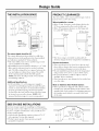
THE INSTALLATION SPACE
34-1/2"-35"
23-3/4"
Handle and
handle standoff
depth is 1-3/4"
1_23-3/4"_
The cutout depth should be 24"
The cutout dimensions shown allow for a full door
swing and access to the pull-out racks when installed
as a built-in in standard 24" deep cabinets.
• The wine chiller, wine reserve and beverage center
can be installed freestanding.
• If installing between frameless cabinets, a 1/9" wide
filler strip or side panel may be needed on hinge
side. The filler strip will act as a spacer between the
case and a(!iacent cabinet door swing. The width
of the opening must include the filler panels.
NOTE: The door should protIude 1" bevond the
surrounding cabinets.
Additional Specifications
• A 120 volt 60Hz., 15 or 20 amp power supply is
required. An individual properly grounded branch
circuit or circuit breaker is recommended, Install a
properly grounded 3-prong electrical receptacle
recessed into the back wall as shown, Electrical must
be located on rear wall as shown, NOTE: OF]
(ground tault interrupter) is not recommended,
PRODUCT CLEARANCES
The wine chiller, wine reserve and be_era-e center is
lhctor_ set for a l l 0 ° door swing.
When installed in a corner:
• Allow 4" rain. clearance on the hinge side fl)r the
90 ° door swing and to allow racks to slide out.
• Allow 10" minimum clearance on the hinge side
fi)r a filll 110 ° door swing.
10" Minimum
to Wall
i
, L
110° .. \
.......... --,"',A)
90° DoorSwing
i-- i
I
I
I
i
\ =
',,, i
I
90° i
R
...... - 4--J,
t
21-5/8"
23-5/8"
4" Minimum
to Wall
• The door swing is rexersible on all models. If
desired, change the door swing before installation.
Choose the location:
• These products may be closed in on the top and
three sides as long as the front is unobstiucted fin.
air circulation and proper access to the door.
• Do not install these products where the temperature
will go below 55°F (13°C) or above 90°F (32°C).
• Do not install where it will be subject to direct
sunlight, heat or moisture.
• These products are not designed to be stacked one
over the other.
Black or Stainless Steel Toekick Options
• These products are shii)ped with a black toekick
installed, An optional stainless steel toekick is also
supplied with each product. For shiI)ping purI)oses,
the stainless steel toekick is secured to the back
of the unit.
SIDE-BY-SIDE INSTALLATIONS
Increase st(>rage capacity by installing tw(> Mon(>gram
beverage centers, wine chillers or wine reserves together.
Or, fin" a complete refreshment center, install any two
of these units together.
• A side-by-side installation requires at least a 47-1/2"
wide opening. No trim kits required.
• Products Illtlst operate fl'om separate, properly
grounded receptacles.
r
34-1/2"-35"
Outlet
li0-1/2'+_14 10-1/_"
t t
is-, ,
/-I/L
47-1/2" Min.
3

Installation Instructions
TOOLS REQUIRED
• #2 Phillips screwdrixer
• A(!i ustable wrellch
PARTS SUPPLIED
• Monogran/ namei)late
• Hardware for changing door swing
• Optional stainless steel toekick with screws
and spacers
• I,elt and right side hinge covers
• Top screw hole cover
GROUNDING THE WINE CHILLER,
WINE RESERVE AND BEVERAGE
CENTER
IMPORTANT - Please read carefllllv.
FOR PERSONAI, SAFETY, THIS APPIJANCE MUST
BE PROPERLY GROUNDED.
Tile power cord of this appliance is equipped with a
three-prong (grounding) plug which mates with a
standard three-prong (gro/mding) wall receptacle to
minimize the possibility of electric shock hazard fl'om
this appliance.
Have tile wall outlet and circuit checked b) a qualified
electrician to make sure file outlet is I)r°l)erlv,,gr()lmded
Where a standard 2-prong wall outlet is enco/mtered,
it is yore" personal responsibility and obligation to
have it replaced with a properly gro/mded 3-prong
wall outlet.
DO NOT, UNDER ANY
CIR(:UMSTANCES, CUT
OR REMOVE THE THIRD
(GROUND) PRONG
FROM THE POWER CORD.
DO NOT USE AN ADAPTER PLU(; TO CONNECT
THE REFRIGERATOR TO A 2-PRONG OUTLET.
DO NOT USE AN EXTENSION CORD WITH THIS
APPI JAN(;E.
STAINING WOOD DRAWER FRONTS
The drawer fronts are unfinished cherry wood.
Dm'ing use, oil fl'om hands may accmnulate and stain
the wood.
• The drawer fronts may be stained and sealed to
match a(!jacent cabinetry. The tinted glass will
make the stained wood appear darker. A true color
match can be seen only when tile door is opened.
• Apply tile stain and sealer according to tile
manufi_cturer's instHlctions. To avoid unpleasant
odor, kee I) tile door open to ventilate and allow
tile stain/sealer to dry completely before using
the product.
ISTEP 11 REMOVE PACKAGING
• Remove corner blocks and foam drawer stops.
• Remove all packing material, tape and protective
plastic coverings.
• Remove stainless steel toekick taped to the back
of tile trait.
CAUTION: Small ol)iects are a ch(,ke
hazard h,r children. Remoxe and discard an) parts
Ilot used,
MISE EN GARDE : I,espetits
objets I)ement (_trangler, les enfants. II fimtjeter
tomes les pi0ces qui ne sont pas utilis0es.
4

Installation Instructions
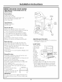
ISTEP 21 REVERSE DOOR SWING
SKIP THIS STEP IF DOOR SWING SUITS THE
INSTALLATION
Parts Included:
• Top left case hinge
• Bottom lefi case hinge
• I,eft and right side decorative hinge cover
• Decorative hinge screw hole cover
• Torx ® driver bit
Tools Required:
• Phillips screwdriver
• Electric drill
Remove the door:
• Flatten tile shipi)ing carton to use as a pad.
• Remove the 2 screws and the toekick. Set aside the
screws and toekick for final installation,
• Use the supplied Torx ® bit aim electric drill to
remove tile 3 screws holding tile top case hinge.
I,ift off the hinge. (Screws will be used to install the
new hinge.)
• i,ifl tile door off tile bottom case hinge.
• Remove tile bottom case hinge pin and bracket.
Rotate the door:
Tile handle will be on tile right side of tile door;
hinges will be installed on the leit side of the case,
• Remove tile door stop and cam riser on tile original
bottom right side of the door.
• Remove tile fill plug on tile top right side
of the door,
• Turn the door over and reinstall the fill plug on the
new lett side,
Reinstall the door:
• Install tile original door stop and cain riser onto
tile bottoln left side of tile door.
• Install tile new supplied bottom case hinge pin and
bracket onto bottom left side.
• Place the door onto the bottom case hinge.
• Install tile supplied lett-hand top case hinge with
the 3 original screws.
• Select the hinge cover marked with an "i,".
• Peel backing off the tape inside the decorative
hinge cox er.
' Install Covers
• Press and snap tile hinge d3/
coxer into place. /:°
V
" Snal) the screw h°le c°xerint° _11
place on the oi)posite side
IMPORTANT:
Check to be sure screws are tight and that tile door
is straight and does not sag. Tile door should swing
freely.
Install
3Hinge _i
Screws i
Remove
TopHinge
Remove
Hinge
Hinge
Pin and
Bracket
Apply Monogram Nameplate:
• Install tile Monogram nameplate See instiuctions
and telni)late on back cover.
Install Toekick
Tile toekick has a
cutout on tile
lett and right
sides,
Remove
the plug
on the lett
side and
reinstall on
the right
side. If wm
choose to install
the stainless steel toekick
reinstall the plug on the right side of that toekick
• Install original screws and spacers or screws and
spacei_ supplied with the stainless steel toekick
Install screws through the spacer standoff toekick
and into the base as shown
5

Installation Instructions
ISTEP 31 LEVEL
• Use an a(!justable wrench to turn the leveling legs
and raise or lower the product.
• A@lst careflllly; the product should be level and
phunb with cabinetr> and should align with a@_cent
toekick height,
Turn Right to Lower
Turn Left to Raise
If you skipped Step 2:
• Select the hinge cover marked "R" or "i,", depending
on door swing.
• Peel backing off the tape inside the decorative
hinge cover. Press and snap into position.
• Snap the screw hole cover into place on the
opposite side.
ISTEP 51 SLIDE PRODUCT INTO
THE CUTOUT
• Carefully, slide the unit into the opening.
Be careful not to entangle power cord.
• Make certain that the door prot_ udes 1" bevond
the surrounding cabinets.
• Check again to be sure the unit is level,
ISTEP 61 INSTALL NAMEPLATE
• Follow inst_ uctions on the back page for installation
of the Monogram nameplate.
ISTEP 71 SET TEMPERATURE
CONTROLS
• The temperature controls are preset. Refer to
the Owner's Manual for more information.
Allow 24 hours for temperature to stabilize.
ISTEP 41 CONNECT POWER
• Connect power cord plug to a i)roperlv grounded
receptacle.
• Check to make sure power is on by opening the door
to see if interior light turns on.
6


TEMPLATE FOR NAMEPLATE LOCATION
Cut on Dotted Line
"]_)" '_ Topof Glass Door
UpperLeft
Cornerof
Glassif Hinge
ison Left
TopofBadge_
UpperRight
Cornerof
Glassif Hinge
ison Right
',4 DoorFrameSide
Monogram.
J
DOORNAMEPLATELOCATION
DoorFrameSide 11_',
£
To position nameplate:
• Cut template along dotted line.
• Hold or tape template behind
glass door so that it is visible fi'om
the fl'ont side.
• Remove backing from nameplate.
• Place nameplate onto front side of
door, matching illustration on the
template.
IMPORTANT: Nameplate must
be placed on the opposite side of
the door handle.
Note: While performing installations described in this book,
safety glasses or goggles should beworn.
Ibr Mo_mgran{ _local wwi_(, in your area, call
1.800. 444. l $4 5.
Note: Pl'o([tl(:[ i1111)FOV( 111( 111 is _ (Oll[illllill_ Cll([( _/x?Of _1_1
(;t neral Electric. Th( refl)r(, mat(rials, apl:)( arance and
sp((ifi(ations at( sul:_je(l Io (llang_ _kithour nolice.
Pub.No.49-60210-4 ]
l
Dwg.No.197D5129PO01
03-04JR
PrintedinSlovenia
Monogram:
GEConsumer & Industrial
LouisvilJe, KY40225
@2004GE Company
-
 1
1
-
 2
2
-
 3
3
-
 4
4
-
 5
5
-
 6
6
-
 7
7
-
 8
8


GE ZDWC240NBBS Installation guide
- Type
- Installation guide
- This manual is also suitable for
Ask a question and I''ll find the answer in the document
Finding information in a document is now easier with AI
Related papers
-
GE Wine Reserve and Beverage Center User manual
-
-
-
GE PCR06WATSS Owner's Manual and Installation Instructions
-
-
-
-
-
-
Other documents
-
Jenn-Air JWC2450ARB Owner's manual
-
 Aetrex iStep version 5.0 User manual
-
Monogram ZDBR240NBS Installation guide
-
 GE Monogram ZDBI240HII Installation guide
-
Monogram ZIFS240NSS Installation guide
-
-
 GE Monogram ZIBI240HII Installation guide
-
Salton WC22RE User manual
-
 GE Monogram Beverage Dispenser ZDWG240 User manual
-
Electrolux E42BS75EPS Owner's manual


