Assembly Guide
Wall System
(Classic, Deluxe)

Recommended Use
Peak Pilates strongly recommends consulting a physician for a complete medical exam before beginning any exercise program. Having a complete medical exam is
particularly important if the user has a family history of high blood pressure, has heart disease, is over the age of 45, smokes, has high cholesterol, is obese, or has not
exercised regularly in the past year.
If, at any time while exercising, the user feels faintness, dizziness, pain, or shortness of breath, he or she must stop immediately.
Important: This manual contains important safety and usage information. Before beginning exercise, read the entire manual, paying specific attention to all cautions
and warnings, and obtain qualified instruction on the use of the Peak Pilates Wall Systems. Use only for the intended exercise. Do not modify the machine. Modifying the
machine in any way will nullify your warranty. Keep this guide handy for future reference. Unsafe or improper use of this equipment due to failure to read and comply with
all requirements and warnings could result in serious injury. Because Peak Pilates cannot anticipate every situation and condition that can occur while using the Peak
Pilates Wall System, we make no representation concerning the safety of this equipment.
There are risks associated with the use of any exercise equipment. The user assumes the responsibility for those risks.
Safety Statement
It is the responsibility of the purchaser of the products to instruct all individuals, whether they are end users or supervising personnel, on the proper use of the equipment.
Inspect the machine including springs, clips, eye bolts, safety chain, and all hardware before use. Do not exercise on the machine if signs of excessive wear, loose
har
dware, or other defects are evident. Do not attempt to fix a defective machine. Instead, notify Peak Pilates immediately.
Do not remove labels for any reason. They contain important information. If the labels are illegible or missing, contact your service representative for replacements.
NOTE: We strongly recommend that all users of Peak Pilates exercise equipment be informed of the following information prior to use.
Proper Use
1. This equipment is only to be used as described by the manufacturer. It is imperative that the Wall System be used properly to avoid injury.
2. Use only components provided by the manufacturer. Do not use parts or accessories or modify the machine in any way not approved by Peak Pilates.
3. Keep a three foot area (about one meter) around the equipment clear of obstructions.
4. Make sure the machine is used on a level surface.
5. Verify that all clips are properly and fully engaged prior to beginning any exercise.
6. Do not use the push-through bar with the push-through bar spring attached from the bottom without both safety chains properly connected. If you have questions
concerning the proper use of the safety chains, contact your Peak Pilates representative.
Specific Operating Warnings
1. Keep your body and loose items such as clothing, hair, and jewelry away from moving parts.
2. Be certain that all clips for the springs and safety chains are fully engaged before beginning to exercise. If you are not sure how to verify proper engagement, seek
assistance.
3. Do not tip the machine during use.
4. Children must not be allowed near this machine. Teenagers and/or physically challenged individuals require supervision.
5. It is the purchaser’s sole responsibility to instruct end users and supervising personnel on the proper operating procedures of the Wall System. We strongly recommend
that the end user’s physical condition be evaluated prior to beginning any exercise program.
Note: Understanding each and every warning to the fullest is critical. If any of these warnings are unclear, ask for clarification from a Peak
Pilates representative.
Warranty
Congratulations on the purchase of your new Wall System. Peak Pilates warrants this machine to be free of manufacturing defects. Any parts that are repaired or replaced
under the terms of this agreement will be warranted for the remainder of the term of the original warranty. This warranty becomes effective on the invoice date of the
original purchase and extends to the time limits indicated below:
This product carries a two year limited warranty on the frame structural components. All other components, with the exception of the upholstery are covered by a one year
limited warranty. If a failure due to workmanship and/or materials occurs, we will, at our discretion, repair or replace the defective components. Upholstery is warranted
against defects in workmanship and/or materials for 60 days. This warranty refers to the Peak Pilates Wall System and covers materials only. It remains in effect only under
the following conditions:
1. This machine is not modified in any way.
2. The machine is only used as specified in the manual and in accordance with generally accepted Pilates exercise practices. Accidents, abuse, misuse or improper service
will not be covered under the provisions of this warranty.
This warranty only applies to the original purchaser of this equipment and is not transferable. All claims must be made within the relevant warranty period specified above.
Warranties outside the U.S. may vary.

Assembling the Springs and Safety Chains
Attach the springs after completing installation of the Wall System structural
components.
Leg Springs
The leg springs are the longest springs. Attach a double ended clip to each end of
each spring and then attach the springs to the eyebolts in the upright poles. The
leg springs can be adjusted between eyebolts depending on the desired height and
tension.
Arm Springs
The arm springs are the smallest in diameter. Attach a double ended clip to each
end of each spring and then attach one end of each spring to an eyebolt on the
roll-down bar (the round wooden bar with eyebolts at each end). The opposite end of
each spring is then attached to an eyebolt on the upright poles.
Push-through Springs
Push-through springs are similar to Reformer springs in length and diameter but
are distinguished by having closed loops at both ends. Attach a safety link to the
end of each push-through spring that will be hooked to an eyebolt on the pole
system. Use a quick snap clip with thumbscrew on the end of each spring that
will attach to the push-through bar. The safety link of one spring will attach to the
second eyebolt from the top. The opposite end of this spring (with the quick snap
clip with thumbscrew) hooks to the eyebolt on the arm of the push-though bar. The
safety link of the second push-through bar spring attaches to an eyebolt on the floor
plate of the Wall System and the quick snap clip end attaches to the corresponding
eyebolt located on the arm of the push-through bar. Be sure to slip the tube-shaped
spring cover sleeve completely over the bottom push-through spring before using.
The sleeve will protect your mat from abrasion when in contact with the spring.
WARNING: Always use the safety chains with safety links when using the push-
through bar spring from the bottom.
The push-through pole system has two safety chains. You must use the safety
chains when the push-through springs are attached to the push-through bar from
the bottom. If you do not take this precaution, the user can be seriously injured
should the push-through bar slip out of the user’s grasp.
Assembling the Safety Chains

Installing the Wall Unit
1. If mounting the Wall System in a facility with pre-existing construction, Peak Pilates
highly recommends first installing a backer board. The material for the backer board
should be 2” x 6” and it needs to be long enough to span at least three wall studs.
If the Wall System is being installed at a facility with new construction, the backer board
can be installed inside of the wall. The photos shown were taken in a facility with new
constrution.
2. Mount the wall mounting plate to the backer board with the included lag bolts. The
center of the plate needs to be 81 1/8” from the floor.
A level should be used to make sure that the plate is parallel to the floor
Once the lag bolts are tightened, cover the heads with the black, plastic plugs provided.
3. Drop a plumb line down from one end of the wall mounting plate. Place the framing
square so that one leg is along and one leg is perpendicular to the wall. The leg that is
perpendicular to the wall should be placed against the plumb line (see next photo).

4. Using the square as a guide, draw a 3 “ long line on the floor starting from 16 3/8”
(extending to 19 3/8”). Repeat on the other side of the wall mounting plate. The floor
mounting plate is located between these two lines. If the Wall System is being installed
using a 2” x 6” external backer board, the line will start at 17 7/8” and extend to 20
7/8”.
5. Attach the floor mounting plate to the floor, parallel to the wall, using the lag bolts
provided or other suitable fastener. Cover the heads with the black, plastic plugs
provided.
6. Place the vertical poles into the fittings on the floor plate. The eye bolts are
positioned toward the top of the Wall System, away from the floor. Do not tighten the set
screws in the fittings at this time.
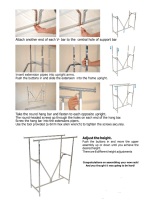
7. Place the top cross pole (with fittings attached) on the vertical poles.
8. Install the 16” extension pipes between the fittings on the top cross pole and the
wall mounting plate.
9. Use the 3/16” allen wrench to tighten the set screws for the extension tubes in the
fittings in the wall mounting plate so the extension pipes do not fall out.

10. Rotate the vertical poles so that the eyebolts are facing away from the wall. Do
not tighten the set screws in the fittings at this time. Leaving the set screws loose
will make installation of the push-through bar easier.
11. Install two of the nylon bushings in each side of the push-through bar.
12. Position the push-through bar between the vertical poles such that the
bushings are in line with a pair of the (3) 3/8” holes in each of the poles. Multiple
hole positions allow the user to select the desired height for the push-through bar
— the middle hole is recommended.
13. Insert one of the shoulder bolts through one of the holes of the vertical poles
from the outside. Then insert the shoulder bolt through a large (3/4” long) metal
spacer, a plywood disc, a large washer; and finally, through the bushing in the
push-through bar.
14. Place a small washer and locknut over the threaded end of each bolt. Tighten
the locknuts until the bar can no longer swing and then back the nuts off just
enough to allow free movement of the push-through bar.
15. Tighten all set screws in the fittings:
Hardware assembly sequence.

TOOLS
The tools required for installation of a Wall System depend on the structure and composition of your wall and floor. Minimally, you will need a
variable speed drill, a Phillips screwdriver bit and the following:
• 3/16” Allen wrench (provided)
• Two 1/2” socket wrenches or one socket and one open ended, box end or crescent wrench
• Framing level
• Plumb line
• Framing square
PARTS LIST
Classic Wall System Standard Features
• Chromed steel pole system (2 upright poles, 1 cross pole, 2 wall anchor poles and ttings)
• 1 push-through bar
• 1 roll-down bar
• 2 safety chains
• Foot loop (pair)
• Springs: 2 push-through springs, 2 leg springs, 2 arm springs
• 1 spring cover (installed on bottom push-through spring)
• Wall mounting plate
• Floor mounting plate
Deluxe Wall System Standard Features
If you have ordered the Deluxe version of the Classic Wall System, you have also received the following:
• 5” x 24” x 84” mat
• 2 mat boxes
• 1 light mat exercise bar 30”
HARDWARE
Notes: If considering new construction, we recommend having your contractor install blocking within the wall or,
if not possible, externally mounting a 2” x 6” (or other suitable backing board) with the centerline located 81 1/8”
from the floor. The backing board needs to span a minimum of three studs and be positioned such that the Wall
System, when assembled in the desired location, is approximately centered.
In addition, if your floor is concrete, you will need to get 4 lag shields from your hardware store. Lag shields are
anchor fittings inserted into holes drilled into the concrete floor. The lag bolts are screwed into the lag shields.
8 double-ended clips
4 safety links (installed on safety chains and
push-through bar springs)
4 quick snap clips with thumbscrews
4 nylon bushings
2 shoulder bolts
12 lag screws
2 small washers
12 black plastic caps
2 metal spacers
2 locknuts
2 large washers
2 wooden disks

Copyright 2013 Mad Dogg Athletics, Inc. All rights reserved. SPIN
®
, Spinner
®
, Spinning
®
, the Spinning logo, Peak Pilates
®
, and Resist-A-Ball
®
are registered trademarks that are owned or used under exclusive license by Mad Dogg Athletics, Inc.
North America
2111 Narcissus Court
Venice, CA 90291 USA
310.823.7008
800.847
.7746
Mad Dogg Athletics, Inc.
2111 Narcissus Court Venice, CA
90291 USA
800.847.7746 or 310.823.7008
Mad Dogg Athletics, Europe B.V.
Scheldeweg 3
3144 ES Maassluis
The Netherlands
+31 1059 04508
www.peakpilates.com
1. Using a safety link, attach one safety chain to the 2nd eyebolts located on each end
of the upright pole.
2. Attach a quick snap clip with thumbscrew to the other end of each chain.
When not in use, the safety chains should be clipped to their home eyebolts allow-
ing them to hang in a loop.
To store the push-through bar, rotate it back through the upright poles. Loop the storage
strap around the push-through bar and clip it to its eyebolt.
Storing the Push-through Bar
/