Raypak RPSF14, RPSF16, RPSF18, RPSF21, RPSF25, RPSF28 Operating instructions
- Category
- Above ground pool accessories
- Type
- Operating instructions

Eective: 01-15-20
Replaces: 12-10-19
P/N 241829 Rev 3
INSTALLATION
AND OPERATION
MANUAL
Models
RPSF14, RPSF16,
RPSF18, RPSF21,
RPSF25, RPSF28
IMPORTANT SAFETY INSTRUCTIONS. READ AND FOLLOW ALL
INSTRUCTION. SAVE THESE INSTRUCTIONS.
NOTE: The instructions in this manual are for the use of qualied individuals specially trained and experienced
in the installation and maintenance of this type of equipment and related system components. Installation and
service personnel are required by some states to be licensed. Persons not qualied shall not attempt to install,
service, or maintain this equipment.
This manual should be maintained in legible condition and kept adjacent to the sand lter or in a safe place for
future use.
SAND FILTER
CONTROLLED COPY approved for factory use on 4/16/2020. RAYPAK PROPRIETARY AND CONFIDENTIAL INFORMATION . Approval signatures on file in Engineering.

2
Revision 3 reects the following changes:
Figure 1 modied on page 7. Parts list descriptions updated on page 13. Warranty certicate added on pages 14 and 15.
CONTROLLED COPY approved for factory use on 4/16/2020. RAYPAK PROPRIETARY AND CONFIDENTIAL INFORMATION . Approval signatures on file in Engineering.

3
CONTENTS
1. WARNINGS ............................................................ 4
Pay Attention to these Terms .................................. 4
2. FILTER OVERVIEW ............................................... 6
3. INSTALLATION ....................................................... 6
Pouring Sand Filter Sand Media ............................. 7
Filter Control Valve Assembly ................................. 7
Valve Key Assembly ................................................ 7
4. START-UP ................................................................ 8
5. GENERAL MAINTENANCE .................................. 8
Filter and Control Valve Functions .......................... 8
Cleaning .................................................................. 8
Filter Backwash Procedure ..................................... 8
Chemical Cleaning .................................................. 9
Winterizing the System ........................................... 9
General ................................................................. 10
6. TROUBLESHOOTING ......................................... 11
7. ILLUSTRATED PARTS LIST ............................... 12
8. WARRANTY .......................................................... 14
CONTROLLED COPY approved for factory use on 4/16/2020. RAYPAK PROPRIETARY AND CONFIDENTIAL INFORMATION . Approval signatures on file in Engineering.

4
AA
WARNING: Risk of electrical shock. More than one
disconnect switch may be required to de-energize the
equipment before servicing.
1. WARNINGS
Pay Attention to these Terms
AA
DANGER
Indicates the presence of immediate hazards which will cause severe personal injury, death or substantial
property damage if ignored.
AA
WARNING
Indicates the presence of hazards or unsafe practices which could cause severe personal injury, death or
substantial property damage if ignored.
AA
CAUTION
Indicates the presence of hazards or unsafe practices which could cause minor personal injury or product
or property damage if ignored.
CAUTION
CAUTION used without the warning alert symbol indicates a potentially hazardous condition which could
cause minor personal injury or product or property damage if ignored.
NOTE
Indicates special instructions on installation, operation, or maintenance which are important but not related
to personal injury hazards.
AA
DANGER: Serious bodily harm or death can result if
this sand lter is not installed and used correctly.
AA
WARNING: BEFORE WORKING ON FILTER:
(1) Stop pump.
(2) Open air release valve.
(3) Release all pressure from system.
NOTE: Always turn o all power to the pool pump before
installing the cover or working on any suction outlet.
AA
WARNING: Installers, pool operators and pool
owners must read these warnings and all instructions
before using the sand lter.
AA
WARNING: This sand lter is intended for use in
swimming pool applications.
AA
WARNING: Most states and local codes regulate the
construction, installation, and operation of public pools
and spas, and the construction of residential pools and
spas. It is important to comply with these codes, many
of which directly regulate the installation and use of this
product. Consult your local building and health codes
for more information.
AA
WARNING: Do not permit children to use or operate
this sand lter.
AA
WARNING: When setting up pool water turnovers
or ow rates the operator must consider local codes
governing turnover as well as disinfectant feed ratios.
AA
WARNING: DO NOT increase pump size; this will
increase the ow rate through the system and exceed
the maximum ow rate stated on the drain cover.
AA
WARNING: For lters intended for use in other than
single-family dwellings, a clearly labeled emergency
switch shall be provided as part of the installation. The
switch shall be readily accessible to the occupants and
shall be installed at least 5 ft (1.52 m) away, adjacent to,
or within sight of the lter.
AA
WARNING: Before installing this product, read and
follow all warnings notices and instructions in this
manual. Failure to follow warnings and instructions
can result in severe injury, death, or property damage.
Please call 1-(877)-213-3726 or refer to www.raypak.com
for more information related to this product.
AA
WARNING: Improper installation, adjustment,
alteration, service, or maintenance can cause property
damage, personal injury, or loss of life.
AA
DANGER: High-pressure release
from the sand lter can cause severe
injury or major property damage due
to parts ying open or apart. Release
all pressure in the sand lter before
doing any work on it. For example avoid
adjusting the lter clamp under pressure
as that can cause it to separate and cause
serious injury or property damage.
CONTROLLED COPY approved for factory use on 4/16/2020. RAYPAK PROPRIETARY AND CONFIDENTIAL INFORMATION . Approval signatures on file in Engineering.

5
AA
CAUTION: Elevated water temperature can
be hazardous. The U.S. Consumer Product Safety
Commission has these guidelines:
1. Spa water temperatures should never exceed 104°F
(40°C). A temperature of 100°F (38°C) is considered
safe for a healthy adult. Special caution is suggested
for young children.
2. Drinking of alcoholic beverages before or during spa
or hot tub use can cause drowsiness which could
lead to unconsciousness and subsequently result in
drowning.
3. Pregnant Women Beware! Soaking in water over
102°F (39°C) can cause fetal damage during the rst
three months of pregnancy resulting in the birth of a
brain-damaged or deformed child.
4. Before entering the spa or hot tub, users should
check the water temperature with an accurate
thermometer; spa or hot tub thermostats may err
in regulating water temperatures by as much as 4°F
(2.2°C).
5. Persons with a medical history of heart disease,
circulatory problems, diabetes, or blood pressure
problems should obtain a physician’s advice before
using pools or hot tubs.
6. Persons taking medications which induce
drowsiness, such as tranquilizers, antihistamines,
or anticoagulants, should not use spas or hot tubs.
CONTROLLED COPY approved for factory use on 4/16/2020. RAYPAK PROPRIETARY AND CONFIDENTIAL INFORMATION . Approval signatures on file in Engineering.

6
2. FILTER OVERVIEW
AA
WARNING: Failure to operate your lter system or
inadequate ltration can cause poor water clarity thus
obstructing visibility in your pool. Poor water clarity may
obscure objects while swimming which, while swimming
and diving, could cause serious personal injury or death.
Never swim in a poor with poor water clarity.
AA
WARNING: Blockage of suction ttings can cause
serious or fatal injury due to drowning. To reduce the
risk of injury, do not permit children to use this product.
3. INSTALLATION
AA
WARNING: Chemical fumes and/or spills can cause
serious corrosion to the lter and pump structural
components. Structurally weakened components can
cause lter, pump, or valve attachments, to separate and
could cause serious bodily injury or property damage.
AA
WARNING: The system's centrifugal pump operates
with electrical voltage and can generate both vacuum
and pressure in the water system. When properly wired
and plumbed this pump will operate in a safe manner.
AA
WARNING: Never work on the pump while it is
running or the power is still connected. High voltage
can cause serious or fatal injury. A suitable ground
fault interrupter (GFCI) should always be installed at the
power supply source of this unit. Article 681-31 of the
NEC requires that a GFCI be used if this pump is used
with a storage pool. Be sure to ground the motor before
connecting to an electrical AC power source. Failure to
ground the motor can cause serious or fatal electrical
shock hazard. DO NOT ground to a gas supply pipe line.
AA
DANGER: High-pressure release
from the sand lter can cause severe
injury or major property damage due
to parts ying open or apart. Release
all pressure in the sand lter before
doing any work on it. For example avoid
adjusting the lter clamp under pressure
as that can cause it to separate resulting
in serious injury or property damage.
AA
WARNING: This lter operates under high pressure.
When any part of the circulating system (e.g., clamp,
lter, valves, etc.) is serviced, air can enter the system
and become pressurized. Pressurized air can cause
the lid or control valve to separate which may result in
serious injury, death, or property damage. To avoid this
potential hazard, follow these instructions.
Before any service to the circulating system (repositioning
the valves, beginning the assembly, disassembly, clamp
adjustment, etc.) do the following:
a. Turn off electricity going both to the pump and
to any automatic controls to avoid accidental
system start-up during servicing.
b. Open the manual air relief valve.
c. Wait until the pressure gauge reads zero (0) to
ensure all pressure is gone.
1. When, or if, the filter clamp is installed, follow the
filter valve and clamp installation instructions
exactly.
2. Follow the system restart instructions exactly after
any service on the circulation system is completed.
3. Maintain circulation system pro-actively. Damaged
and worn parts must be replaced immediately (e.g.,
clamp, pressure gauge, relief valve, O-rings, etc.).
4. Mount the filter properly and position it according to
all provided instructions.
The sand lter is designed to last for years of use when
maintained properly. Its purpose is to extract suspended
particles (dirt) from the pool water, thereby keeping the
water clear. A special lter sand is used to trap and collect
the particles. The ltering action occurs as the water ows
through the unit and the particles are trapped in the sand
bed which forms the lter.
Water enters through a valve on the top of the lter and
then passes evenly though the lter. The ltered water
then ows through the bottom side of the lter, up through
the stand pipe, through a valve on the top, and then back
into the pool though piping or hoses.
In terms of capacity, please ensure that the volume of
water cleaned in every 24-hour cycle is at least double the
total volume in the pool so proper cleaning can occur.
Over time, enough particles will collect in the lter sand to
impede the easy ow of water though it and this resistance
will cause the lter pressure to build to such a point that
the lter needs cleaning (purging). That process is called
backwash.
The backwash procedure reverses the ow of water
through the lter to ush out the captured particles and
discharge them, not back into the pool, but into a waste
line. A valve on the unit top is set to BACKWASH. This is
a manual procedure. After running the BACKWASH cycle,
reset the value to FILTER manually to resume normal
ltration.
The sand lter, while designed to remove particles and/or
other debris suspended in the water, does not adjust the
pH level or the bacterial count.
Sanitation and pH balancing are specialized and important
areas that are covered with other tools, equipment and
knowledge and as such are beyond the scope of this
manual. Roughly speaking, pH level should be in the range
of 7.2~7.6, and chlorine about 1~2 ppm, but pool chemistry
involves much more than this. Check the local codes and
with pool service specialists for required instruction.
CONTROLLED COPY approved for factory use on 4/16/2020. RAYPAK PROPRIETARY AND CONFIDENTIAL INFORMATION . Approval signatures on file in Engineering.

7
Pouring Sand Filter Sand Media
Common tools such as screwdrivers, wrenches, and
consumables like pipe sealant for plastic adapters are
required for the installation and service of the sand lter.
See the schematic for layout information, Figure 4.
1. The filter should be placed on a level concrete slab,
very firm ground, or equivalent. Orient the filter so
that the piping connections and control valve are
convenient and accessible for operation and service.
2. Filter sand media is loaded through the top opening
of the filter as follows:
a. Loosen the flange clamp and remove the filter
control valve (if previously installed).
b. Cap the internal pipe with a plastic cap to prevent
sand from entering it.
c. We recommend filling the tank approximately 1/2
full with water to provide a cushioning effect when
the filter sand is poured in. This helps protect the
under-drain laterals from excessive shock.
d. Carefully pour in the correct amount and grade
of filter sand while making sure the center pipe
remains centered in the opening. When done,
the sand surface should be leveled and should
rise up to about the middle of the filter tank. Next
remove the plastic cap from the internal pipe.
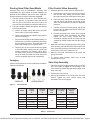
Packaging
A hose barb kit and union kit are included and needed to
make the connections.
UNION KIT HOSE BARB KIT
Figure 1. Connection Kits
Model
Height
in. (mm)
A
Diameter
in. (mm)
B
Valve Port
Size
Inch
Silica Height
in. (mm)
C
Silica 16/30*
Weight
lb. (kg)
RPSF14 28.6 (726) 13.8 (350)
1.5"
6.3 (160) 44 (20)
RPSF16 29.8 (757) 15.7 (400) 6.9 (175) 77 (35)
RPSF18 32.0 (814) 17.7 (449) 8.3 (210) 99 (45)
RPSF21 33.3 (845) 20.7 (527) 9.3 (235) 209 (85)
RPSF25 37.4 (950) 24.7 (627) 11.8 (300) 319 (145)
RPSF28 40.2 (1020) 27.7 (703) 13.0 (330) 462 (210)
*Note: Suggested silica weight with differences in filter media size for reference only
Table A. Dimensions
Filter Control Valve Assembly
1. Assemble the filter control valve into the filter tank.
a. Insert the filter control valve, with O-ring in place,
into the tank neck, taking care that the center
pipe slips into the hole at the bottom of the valve.
b. Place two plastic clamps around the valve flange
and tank flange and tighten just enough so the
valve may be rotated on the tank for alignment
purposes.
c. Carefully screw the pressure gauge, with O-ring
in place, into the tapped hole on the valve body.
Do not over-tighten.
d. Connect the pump to the control valve opening
marked PUMP. After connections are made,
tighten the valve flange clamps with the
screwdriver, tapping around the clamp with the
screwdriver handle to help seat the valve flange
clamp.
2. Make the connection from the pool pipe to the control
valve opening, marked RETURN, and complete the
other necessary plumbing connections such as the
suction lines to the pump, waste line, etc.
3. Make the electrical connections to the pump per
pump instructions.
4. To prevent water leakage, make sure all pipe
connections are tight.
Valve Key Assembly
1. Place the valve key so that wedge opening is at TOP
port. See handle in Figure 4. The flat edge of the
cover screw lug should align with the flat edge of the
body screw lug.
2. Position the cover O-rings.
3. Secure the assembly to the body with the cover
screws. Tighten the cover screws evenly and
alternately. Do not over-tighten.
CONTROLLED COPY approved for factory use on 4/16/2020. RAYPAK PROPRIETARY AND CONFIDENTIAL INFORMATION . Approval signatures on file in Engineering.

8
4. START-UP
NOTE: During initial clean-up of the pool water it may
be necessary to backwash more frequently due to a
possibly unusually heavy initial dirt load in the water.
AA
WARNING: Always turn the pump o before
changing valve positions. Changing valve positions
while the pump is running can damage the control valve,
which may cause serious injury or property damage.
1. Make sure the correct amount of filter media (specified
sand) is put into the tank and that all connections
have been connected and secured.
2. Depress the multiport valve handle and rotate it to
the BACKWASH position. Always depress the valve
handle before turning it to prevent damage to the
multiport valve seal.
3. Prime and start the pump according to the pump
instructions. Always depress the valve handle before
turning it to prevent damage to the multiport valve
seal. Once water is flowing out of the waste line, run
the pump for at least 1 minute. An initial backwash of
the filter is recommended to remove any impurities or
fine sand particles in the sand media.
4. Turn the pump off and set the multiport valve to RINSE
position. Start the pump and operate it until water in
the view glass is clear, about 1/2 to 1 minute. Turn
the pump off and set the valve to FILTER position
and restart the pump. The filter is now operating in
the normal filter mode filtering dirt particles from the
pool water.
5. Adjust pool suction and return valves to achieve
desired flow. Check system and filter for water leaks
and tighten connections, bolts and nuts, as required.
6. Note the initial pressure gauge reading when the filter
is clean. It will vary from pool to pool depending upon
the pump and general piping system. Over time, as
the filter removes dirt and impurities from the pool
water, the accumulation of dirt in the filter will cause
the pressure to rise and diminish the water flow. When
the pressure gauge reading is 8-10 PSI higher than
the initial "clean" pressure it started with, it is time to
backwash the filter (see Filter Backwash Procedure).
5. GENERAL MAINTENANCE
NOTE: It is essential to set up a regular schedule to
clean the sand lter by BACKWASHING and RINSING to
provide clean, safe, and healthy swimming water. The
time between cleans and the length of cleaning time will
depend on size of pool, usage, and other environmental
conditions. Consult your local pool professional to work
out a program that best suits your pool.
It is important to maintain a regular service schedule
program with pool equipment to ensure the best operation
and longest lasting results. Regular maintenance can
identify any potential issue early and save on expensive
maintenance at a later date. See Table B.
Filter and Control Valve Functions
Information is provided in Figure 3 and Table C for using
the control valve to regulate all the lter functions.
Cleaning
AA
WARNING: Failure to operate your lter system
or inadequate ltration can cause poor water clarity
obstructing visibility in your pool. Poor water clarity may
obscure objects in the water which, while swimming and
diving, could cause serious injury or death. Never swim
in a pool with poor water clarity.
Cleaning your lter will give you better quality water
that is clean, clear, and safe for swimming. It is highly
recommended to clean on a regular basis. Monitor the
pressure gauge and to switch on BACKWASH when an
increase of 8-10 PSI is noted compared to the pressure
gauge reading when the lter is clean.
Filter Backwash Procedure
AA
WARNING: To prevent equipment damage and
possible injury, always turn pump o before changing
valve position.
Perform the backwash operation as follows:
1. Turn off the pump.
2. Change the position of the multiport valve handle
from FILTER to BACKWASH
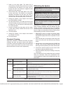
C
B
A
Figure 2. Dimensions
CONTROLLED COPY approved for factory use on 4/16/2020. RAYPAK PROPRIETARY AND CONFIDENTIAL INFORMATION . Approval signatures on file in Engineering.

9
Period Check Point Related Problems
Weekly Check pressure gauge
If pressure increases by 8-10 PSI, then backwash and rinse the lter as per
instructions
Quarterly
Check all gaskets and pressure
gauge.
Isolate and turn o the pump. Remove all gaskets and turn over. You can also
apply a silicone-based grease to extend gasket life. If dry, then contact your
local pool professional for replacement
Check around the unit for leaves,
debris or signs of ooding.
Replace any debris that is restricting air circulation around the lter. If in a
ood prone location, rectify
Check for any insects, ants, etc.
It is a good practice to use a good quality surface spray around your
equipment. Make sure all units are turned o and then spray around all units
to eliminate any insects, ants, etc
Check for any leaks
If you notice any water leaking from the lter or other equipment, check the
gaskets rst and reseal. If leaks continue, contact your local pool professional
to assess and rectify
Table B. Maintenance Service Schedule
3. Power up the pump again. The water flow is
automatically reversed through the filter so the water
is directed from the bottom of the tank, then up
through the sand. This flushes the trapped dirt and
debris out of the waste line.
4. Check through the visual sight glass on the multi-
function valve outlet. The duration of the backwash
operation will depend on how dirty your filter is.
Continuously check the sight glass until the water
becomes clear, after which the pump is turned off.
5. Change the position of the multiport valve handle
from BACKWASH to RINSE.
6. Turn the pump back on. The water flow will now be
directed through the sand bed and then out through
the waste line. This will settle the sand bed properly
for normal operation.
7. Continue checking the sight glass until the water
is clear which usually is about half the time of the
backwash cycle.
8. Turn the pump off.
9. Change the position of the multiport valve handle
from RINSE to FILTER.
10. Turn the pump on.
Chemical Cleaning
Algae load, calcication, sanitation and other poor water
conditions will aect the proper function and eciency
of the lter. Follow local guidelines and pool professional
advice to optimize these other key facets of water quality
that the lter does not control, but is impacted by.
Winterizing the System
AA
CAUTION: Allowing water to freeze in the system will
damage the system and cause potential water damage/
ooding and potential property damage.
AA
CAUTION: The Multiport Valve should be left in the
"Winterize" position during the shutdown season so
the rubber seal of the valve diverter has no pressure on
it. Failure to do so can damage the valve diverter seal
which can cause property damage from leaking water.
CAUTION: Only use Propylene Glycol as an anti-freeze,
as other anti-freeze solutions are highly toxic and will
damage the pump.
Winterizing is a process for protecting your sand lter
during freezing conditions that can damage all pool
ltration equipment. Damage results from ice expansion
(ice takes up more volume than liquid water) cracking the
parts. It is highly recommended to take the following steps
when preparing your lter for winter conditions:
1. Backwash the filter for at least 30 minutes before
closing down the pool for winter. This will clean the
filter bed thoroughly and remove any debris from the
system.
2. Drain the filter tank by removing the drain cap at the
bottom of the filter tank. Also leave the cap off during
winter.
3. Set the control valve handle between the RINSE and
FILTER. This will lift the handle and help with the
draining process by allowing air to enter into the tank.
4. Unscrew the pressure gauge from the control valve
and store the pressure gauge indoors.
5. Drain and winterize the pump according to the pump
instructions.
This is an ideal time for any repairs that may be required
during the o-season. Most pool professionals have
recommendations of what will be needed before the next
pool season.
CONTROLLED COPY approved for factory use on 4/16/2020. RAYPAK PROPRIETARY AND CONFIDENTIAL INFORMATION . Approval signatures on file in Engineering.

10
Valve Position Function
FILTER
This is the standard normal operation position of your ltration system. The water ows in from your pool
and is distributed across the top of the sand bed in the lter. Through pressure, this water then ows down
through the sand allowing debris to be removed from the water and collected in the sand bed. Water is then
routed up through the laterals and the center stem pipe and is returned to the pool, usually via some form
of sanitation and/or heating. The FILTER position can also be used for manual vacuuming and cleaning.
BACKWASH
This position is used when your sand lter’s sand bed needs cleaning. Use the pressure gauge to monitor
when this is required, usually 8-10 PSI above the operation of a clean lter. When BACKWASH is selected,
the water ow is reversed and goes down the stem pipe and out through the laterals. This lifts the sand
bed and allows debris to be taken out of the lter and through the waste pipe. The sight glass will show the
quality of the water. Continue BACKWASH until the water visually clears.
RINSE
This setting is used after completing the BACKWASH cycle. In the RINSE setting, water is taken
from the pool and distributed on the sand bed. This downward ow settles the sand bed, disturbed
from backwashing, and carries any remaining loose dirt through the waste line. By using RINSE after
backwashing, you will eliminate any debris from returning to the pool water. Rinse until you see clear water
through the transparent sight glass. Time needed is about half the time of a BACKWASH cycle.
WASTE
The WASTE position allows you to pump excess water from the pool directly down through the waste pipe.
This position is useful after heavy rains when the water level is too high. Water is directed straight through
the multiport control valve and bypasses the lter, going directly to waste. You can also use this position to
vacuum heavy concentration of debris from the pool.
RECIRCULATE
Similar to the WASTE setting, RECIRCULATE allows the water to bypass the lter but go straight back
to the pool. This is a useful setting if you have applied some chemicals that need to be circulated, but not
removed by the lter. In addition, if a leak develops in the lter, use recirculate to continue circulating water
until leaks are located for xing.
CLOSED
The CLOSED setting acts like a valve and prevents the ow of water through the tank, and is particularly
useful when doing any maintenance on the ltration system.
Table C. Multiport Valve Position Functions
WASTE
FILTER
BACKWASH
RINSE
WASTE
RECIRCULATE
CLOSED
WASTE WASTE
WASTE WASTE WASTE
IN FLOW
OUT FLOW
IN FLOW
OUT FLOW
IN FLOW
OUT FLOW
IN FLOW
OUT FLOW
IN FLOW
OUT FLOW
IN FLOW
OUT FLOW
Figure 3. Multiport Valve Position Functions
General
A boss with pipe tap is provided for installing the optional
inuent pressure gauge.
Valve Service
Stop the pump and close the gate valves on both the
suction and discharge sides before proceeding.
1. Set handle in the filter position.
2. Remove the cover screws.
3. Lift the cover and key assembly out.
CONTROLLED COPY approved for factory use on 4/16/2020. RAYPAK PROPRIETARY AND CONFIDENTIAL INFORMATION . Approval signatures on file in Engineering.

11
6. TROUBLESHOOTING
The table below identies some of the main issues that may be encountered with your sand lter. This should assist
in solving most of the major problems. It is highly recommended that regular maintenance of your swimming pool
equipment, including the sand lter, be performed by a qualied pool professional. This will extend the life of your
equipment and give better performance.
Problem Cause Action
Sand entering the pool
Sand size is too small and getting through laterals Change sand
Flow rate on the pump is too high and pushing sand
through laterals
Adjust ow rate
Sand bed calcied due to poor water chemistry Adjust chemistry (pH balance)
Broken lateral Repair
Loose center-pipe Re-tighten
Too much sand in the tank Reduce sand level
Multiport valve not correctly positioned in the lter Remove and reattach correctly
Too much air in the lter Purge air
Sand coming out of waste line
Flow rate on the pump is too high and lifting sand too
high during backwash
Adjust ow rate, change the pump
as needed
Pool water is cloudy due to
poor ltering
Sand bed is dirty and requires backwashing Backwash to remove dirt
Incorrect sand has been installed Replace with correct specication
Algae build-up in the lter due to poor water
chemistry
Adjust chemistry (chlorine)
Calcied sand bed due to poor water chemistry Adjust chemistry (pH balance)
Heavy swimmer usage Backwash more frequently
Flow rate on the pump is incorrect for lter size and
pool size
Adjust ow rate, change the pump
as needed
Backwashing cycle is too short Increase backwash cycle length
Backwash line is too small restricting water ow Increase pipe size
Filter leaking water
Tank cracked Replace
Drain plug not tight Re-tighten
Valve to tank O-ring damaged Replace
Multiport control valve leaks
Handle is not properly located in selected setting Re-assemble correctly
Valve to tank O-ring damaged Replace
Valve cover O-ring damaged Replace
Pressure gauge O-ring damaged Replace
Abnormal loss of pool water
Leak inside control valve Re-tighten or replace as needed
Leak from pool or PVC piping Inspect, repair, replace
High pressure lter
Filter requires backwashing Backwash
Calcied sand bed due to poor water chemistry Adjust chemistry (pH balance)
Return lines too small for pump ow rate Increase pipe size
Low pressure in lter
Multiport control valve incorrectly set Re-assemble correctly
Pump ow rate is too slow Check speed and control valves
Air leak in pump suction Check seals and tighten as needed
Table D. Troubleshooting
CONTROLLED COPY approved for factory use on 4/16/2020. RAYPAK PROPRIETARY AND CONFIDENTIAL INFORMATION . Approval signatures on file in Engineering.

12
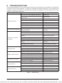
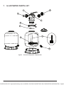
1
6
5
7
8
2
3
4
9
Figure 4. Sand Filter Components – Exploded View
7. ILLUSTRATED PARTS LIST
CONTROLLED COPY approved for factory use on 4/16/2020. RAYPAK PROPRIETARY AND CONFIDENTIAL INFORMATION . Approval signatures on file in Engineering.

13
Item Description Raypak Order No.
1 Kit - 6 Way Valve 1-1/2" 018214F
2
3
4
5
6
Kit - Lateral Assy with Center Pipe RPSF14
018216F
Kit - Lateral Assy with Center Pipe RPSF16
018217F
Kit - Lateral Assy with Center Pipe RPSF18
018218F
Kit - Lateral Assy with Center Pipe RPSF21
018219F
Kit - Lateral Assy with Center Pipe RPSF25
018220F
Kit - Lateral Assy with Center Pipe RPSF28
018221F
Kit - Lateral Assy 115mm 018222F
Kit - Lateral Assy 126mm 018223F
9 Kit - Water Drain PVC 018224F
018215F
7
8
018252F
Kit - Union and Pressure Gauge
Kit - Locking Clamp
CONTROLLED COPY approved for factory use on 4/16/2020. RAYPAK PROPRIETARY AND CONFIDENTIAL INFORMATION . Approval signatures on file in Engineering.

14
Catalog Number: 6000.955
Effective 01/01/20
LIMITED WARRANTY
ABOVE GROUND SWIMMING POOL FILTERS
Models: RPSF14, RPSF16, RPSF18, RPSF21, RPSF25, RPSF28
SCOPE OF WARRANTY
Raypak, Inc. (“Raypak”) warrants to the original owner that the above ground swimming pool filter models
listed above and sold with this Limited Warranty certificate (the “Filter”), when installed in the United
States of America with a pool, will be free from defects in materials and workmanship under normal use
and service for the Applicable Warranty Period defined herein. In accordance with the terms of this
Limited Warranty, Raypak will, at its option, repair or furnish a replacement for the FILTER or any
defective part of the FILTER that fails in the normal use and service during the Applicable Warranty
Period. The repair or replacement will be warranted for only the unexpired portion of the original
Applicable Warranty Period, or the Extended Warranty Period, as the case may be.
EFFECTIVE DATE
The Effective Date of this Limited Warranty is the date of original installation if properly documented. If
you are not able to provide documentary proof of the date of original installation, the Effective Date will be
the date of manufacture plus thirty (30) days. All Applicable Warranty Periods specified in this Limited
Warranty are measured from the Effective Date.
APPLICABLE WARRANTY PERIOD – UNREGISTERED
If the FILTER is installed with a pool, the Applicable Warranty Period is ninety (90) days from the
Effective Date, parts only, for the FILTER and component parts.
EXTENDED WARRANTY PERIOD – REGISTERED
If, within 90 days of the Effective Date, the FILTER is installed in a pool at a single family
residential dwelling and registered with Raypak (www.raypak.com/warranty), then the Applicable
Warranty Period is one (1) year from the Effective Date for the FILTER and component parts.
LABOR AND SHIPPING COSTS
This Limited Warranty does NOT cover any travel time or any labor costs. Furthermore, unless applicable
state law provides otherwise, this Limited Warranty does NOT cover any shipping costs to and from
Raypak’s designated service provider or to or from the installation site. All of the foregoing costs and
expenses are your responsibility, unless applicable state law provides otherwise.
WARRANTY EXCLUSIONS
This Limited Warranty does NOT apply:
1. if the FILTER has been moved from its original place of installation, or if the original owner no longer
owns the property where the original installation was made;
2. if the FILTER is not properly installed in a pool in accordance with applicable local codes and
ordinances, good trade practices and the manufacturer’s installation instructions;
3. if the rating plate(s) or serial number(s) are altered or removed;
4. if the FILTER is modified in any way, or if non-factory authorized accessories or other components are
used in conjunction with the FILTER;
5. to damage, malfunctions or failures resulting from failure to properly install, operate or maintain the
FILTER in accordance with the manufacturer’s instructions;
6. to damage, malfunctions or failures resulting from abuse, act of nature, accident, fire, flood, freeze,
lightning or the like;
7. to damage, malfunctions or failures resulting from connected system control devices;
8. to performance problems caused by improper sizing of the FILTER or electric service voltage,
wiring or fusing;
9. to damage, malfunctions or failures resulting from any alteration, including the use of any attachment,
including without limitation, any energy saving device not authorized by the manufacturer;
8. WARRANTY
CONTROLLED COPY approved for factory use on 4/16/2020. RAYPAK PROPRIETARY AND CONFIDENTIAL INFORMATION . Approval signatures on file in Engineering.

15
10. to damage, malfunctions or failures resulting from misuse or neglect, including but not limited to,
freeze-ups.
HOW TO MAKE A WARRANTY CLAIM
You should immediately notify your dealer and provide proof of purchase model number serial number
and date of installation. If the dealer is not available, please contact Raypak customer service at 805-
278-5300. Proper authorization MUST be obtained PRIOR to any repairs for the Limited Warranty
to apply. This Limited Warranty is VOID if the product is repaired or altered in any way by ANY
persons or agencies other than those authorized by Raypak.
When requesting support please be ready to supply the model number, serial number, date of original
installation and a description of the problem. Raypak reserves the right at all times to inspect, or require
the return of, the defective FILTER or component part and to verify warranty coverage at its factory.
Warranty service CANNOT be initiated until the status of the warranty coverage has been
established.
EXCLUSIVE WARRANTY-LIMITATION OF LIABILITY
THE LIMITED WARRANTY IS THE ONLY WARRANTY PROVIDED BY RAYPAK IN
CONNECTION WITH THE FILTER AND ITS COMPONENT PARTS. NO ONE IS
AUTHORIZED TO MAKE ANY OTHER WARRANTIES ON RAYPAK’S BEHALF. ANY
IMPLIED WARRANTIES, INCLUDING MERCHANTABILITY OR FITNESS FOR A
PARTICULAR PURPOSE, SHALL NOT EXTEND BEYOND THE APPLICABLE
WARRANTY PERIOD SPECIFIED IN THIS LIMITED WARRANTY. RAYPAK’S SOLE
LIABILITY WITH RESPECT TO ANY DEFECT SHALL BE AS SET FORTH IN THIS
LIMITED WARRANTY. IT IS AGREED THAT RAYPAK SHALL HAVE NO LIABILITY
WHETHER UNDER THIS LIMITED WARRANTY OR IN CONTRACT, TORT OR
NEGLIGENCE OR OTHERWISE FOR CLAIMS FOR SPECIAL, INCIDENTAL OR
CONSEQUENTIAL DAMAGES (INCLUDING NO LIABILITY FOR DAMAGE FROM
WATER LEAKAGE), ALL OF WHICH ARE EXPRESSLY EXCLUDED,
NOTWITHSTANDING ANY FAILURE OF ESSENTIAL PURPOSE OF ANY LIMITED
REMEDY. SOME STATES DO NOT ALLOW LIMITATIONS ON HOW LONG AN
IMPLIED WARRANTY LASTS, OR FOR THE EXCLUSION OF INCIDENTAL OR
CONSEQUENTIAL DAMAGES, SO THE ABOVE LIMITATION OR EXCLUSION MAY
NOT APPLY TO YOU. THIS LIMITED WARRANTY GIVES YOU SPECIFIC LEGAL
RIGHTS, AND YOU MAY ALSO HAVE OTHER RIGHTS WHICH VARY FROM STATE
TO STATE.
We suggest you immediately record the model, serial number, date of original installation and receipt of
purchase and retain this Limited Warranty Certificate in the event warranty service is needed.
DO NOT RETURN THIS DOCUMENT TO RAYPAK. KEEP IT WITH YOUR POOL FILTER OR
BUSINESS RECORDS.
Register your product online at www.raypak.com/warranty
RAYPAK, INC., 2151 Eastman Avenue, Oxnard, CA 93030 • (805) 278-5300 FAX (800) 872-9725
CONTROLLED COPY approved for factory use on 4/16/2020. RAYPAK PROPRIETARY AND CONFIDENTIAL INFORMATION . Approval signatures on file in Engineering.

Raypak, Inc., 2151 Eastman Avenue, Oxnard, CA 93030 (805) 278-5300 Fax (805) 278-5468
www.raypak.com
CONTROLLED COPY approved for factory use on 4/16/2020. RAYPAK PROPRIETARY AND CONFIDENTIAL INFORMATION . Approval signatures on file in Engineering.
-
 1
1
-
 2
2
-
 3
3
-
 4
4
-
 5
5
-
 6
6
-
 7
7
-
 8
8
-
 9
9
-
 10
10
-
 11
11
-
 12
12
-
 13
13
-
 14
14
-
 15
15
-
 16
16


Raypak RPSF14, RPSF16, RPSF18, RPSF21, RPSF25, RPSF28 Operating instructions
- Category
- Above ground pool accessories
- Type
- Operating instructions
Ask a question and I''ll find the answer in the document
Finding information in a document is now easier with AI
Related papers
-
Raypak RPAGP75, RPAGP100, RPAGP102, RPAGP150, RPAGP152 Operating instructions
-
-
-
-
Raypak 268A Professional Pool and Spa Heater User manual
-
Raypak 266 User manual
Other documents
-
Franke 8585563 Datasheet
-
Pentair METEOR U78-767P Owner's manual
-
Rheem Electric Spa-Pak Heaters Warranty
-
-
VEVOR HCP750A-D User manual
-
VEVOR HCP550A-D User manual
-
AquaPRO AL50 SERIES Owner's manual
-
emaux MAX SERIES MFS27A User manual
-
Pentair CRISTAL-FLO II Installation guide
-
Pentair S8D110 User manual