Page is loading ...

*L1RC/*GC1RC 92+ Residential Gas Furnace
Horizontal Installation Kit
Installation Instructions
These instructions are primarily intended to assist
qualified individuals experienced in the proper
installation of this appliance. Some local codes
require licensed installation/service personnel
for this type of equipment. Read all instructions
carefully before starting the installation.
The components of this kit are listed in Table
1. If any parts are missing, contact your local
distributor.
WARNING:
This conversion kit for horizontal
installation is to be installed by a
qualified service technician in accor-
dance with these instructions and all
codes having jurisdiction. Failure to
follow these instructions could result
in serious injury, property damage, or
death. The qualified service technician
performing this work assumes respon-
sibility for this conversion.
Table 1. Parts List -
Horizontal Conversion Kit #904079 -
2” Vent
Description Qty.
Installation Instructions 1
1/2” Barbed Fitting 1
3/4” Barbed Fitting 1
2” to 1/2” PVC Reducer Bushing 1
2” PVC Tee 1
Tube, Drain Hard “J” (5”x2”) 1
Tube, Soft (10”) 1
Tube, Soft (50”) 1
Tube, High Temp.
(Grey, 25”) 1
Vinyl Cap (5/8”) 1
Vinyl Cap (1/2”) 1
Hose Clamp (7/8” Dia.) 3
3” to 2” Reducer 1
Pressure Switch (0.90” w.c.) 1
Wire (20”) 1
Check the contents of the installation
kit against this parts list, and familiarize
yourself with the components.
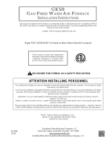
Figure 1. 90+ Upflow Horizontal Installation
Suspended in Attic or Crawl Space
Table 2. Parts List -
Horizontal Conversion Kit #904080 -
3” Vent
Description Part No. Qty.
Installation Instructions 1
3/4” Barbed Fitting 2
3” to 3/4” PVC Reducer Bushing 1
3” PVC Tee 1
Tube, Drain Hard “J” (5”x2”) 1
Tube, Soft (10”) 1
Tube, Soft (50”) 1
Tube, High Temp. (Grey, 25”) 1
Vinyl Cap (5/8”) 1
Vinyl Cap (1/2”) 1
Hose Clamp (7/8” Dia.) 3
Pressure Switch (0.90” w.c.) 1
Wire (20”) 1
Check the contents of the installation
kit against this parts list, and familiarize
yourself with the components.

2
CAUTION:
Damage to the product resulting from
failure to follow instructions or use of
unauthorized parts may void the manu-
facturer’s product warranty coverage.
General
The 92+ upflow furnace can be installed hori-
zontally in an attic, basement, crawl space or
alcove. This furnace can be installed horizontally
to the clearances listed in Table 3 on a platform
or on the ceiling rafters. Note that the platform
and the ceiling rafters must be able to support
the weight of the furnace being installed. It can
also be suspended from a ceiling in a basement
or utility room in either a right to left airflow or
left to right airflow (See Figure 1).
If the furnace is to be suspended from the ceiling,
it will be necessary to use steel straps around
each end of the furnace. These straps should be
attached to the furnace with sheet metal screws
and to the rafters with bolts. The furnace could
also be suspended by an angle iron frame bolted
to the rafters (See Figure 1).
When installed horizontally, the furnace must
be raised approximately 6 inches above the
surface to allow the drain trap assembly to
hang vertically below the furnace. This will
allow for proper drainage of the condensate
from the furnace.
Clearances to Combustibles
This furnace, when installed horizontally, is de-
signed for the minimum clearances to combus-
tible material listed in Table 3. Note that access
for positioning and servicing the unit must be
considered when locating unit. Twenty four (24)
inches is the minimum required clearance from
the front of the unit for servicing. Thirty (30)
inches is the minimum required clearance from
the front of the unit for positioning. Thirty six (36)
inches is the recommended clearance from
the front of the unit. Please note that a panel
or door can be located such that the minimum
clearance on the rating plate is satisfied, but
that panel or door must be removable and allow
the appropriate clearance for your installation.
Refer to the furnace name plate, located inside
the furnace cabinet, for specific model number
and clearance information.
Venting Requirements
NOTE: When installing a *RC120 furnace, it is
required to use a 3” vent kit (Part No. 904080).
In order to ensure complete drainage of all
Figure 2. 90+ Upflow Furnace as Shipped
From the Factory
Top
Outlet
Side
Return
Side
Bottom
Table 3. Minimum Clearances to
Combustible Materials
In-line
Drain
Grey
Tubing
30" Soft
Tubing
Pressure
Switch
"J" Drain
Trap
Assembly
Soft "J"
Tubing
Header
Box
DIMENSION
MINIMUM
CLEARANCE (INCHES)
Outlet Side 1
Return Side 0
Vent 0
Back 0
Bottom 0
Top 0
Front 1*
*24” is the minimum clearance for servicing.
36” is the recommended service clearance.

3
condensate, an additional “T” shaped vent drain
assembly must be installed in-line with the vent
piping (see Figures 3 and 4). The “Tee” shaped
vent drain assembly consists of a 2” PVC with
a 2” to 1/2” PVC reducer bushing glued into the
tee. See Figures 3 and 4 for your installation in
order to glue the tee. Next glue the 1/2” barbed
fitting into the reducer bushing. Ensure that all
glued joints are tight and sealed. A 50” piece of
soft tubing is supplied with the horizontal instal-
lation kit. Assemble this piece to the barb at
the bottom of the “T” assembly. NOTE: Ensure
a tight fit in order to avoid any leakage of the
condensate. Loop the tubing in a circle in order
to create a trap and secure. The drain tubing
can then be routed out the same drain as the
furnace drainage system.
Follow the same instructions for the installation
of the furnace and maximum vent pipe lengths
as given in the installation instructions provided
with the furnace. NOTE: A 3” to 2” reducer is
also supplied with the horizontal installation kit,
if 3” piping is preferred coming off the “T” shaped
vent drain assembly. If using alternate configura-
tion (shown in Figures 3 and 4), reducer must
be installed above drain assembly to ensure
drainage.
Conversion for Horizontal Right
Installation (See Figures 2 & 3)
1. Remove the hard “J” tube drain trap assem-
bly. Discard the assembly with the exception
of the 30” piece of soft tubing.
2. Place the 5/8” cap plug over the drain tap
in the header box from which the “J” drain
trap assembly was removed.
3. Remove the soft “J” tubing between the inline
drain and the header box, and discard.
4. Place a 5/8” cap plug over the drain port on
the inline drain where the soft “J” tube was
removed.
5. Mount the white pressure switch to the fur-
nace with sheet metal screws in the holes
provided.
6. Remove one of the orange wires from the
pressure and attach to the white pressure
switch.
7. Attach the orange wire supplied in the kit
between the white pressure switch and the
factory installed pressure switch.
8. Remove the 1/4” vinyl cap from the bottom
of the header box.
9. Attach the grey tubing supplied in the kit
from the white pressure switch to the port
on the header box.
10. Assemble the 10” piece of soft tubing to the
drain tap located on the right side of the
header. Feed the tube through the round
hole located in the right side of the cabinet
wrapper. NOTE: A downward slope must
be maintained on the tube as it is routed
through the furnace (when the furnace is
in the horizontal position).
11. Assemble the 5” tall end of the hard “J” tube
to the end of the soft tube located outside of
the furnace. Secure the connection using
one of the 7/8” hose clamps supplied with
the installation kit.
12. Assemble the 30” piece of soft tubing re-
moved from the factory installed “J” tube
drain trap to the 2” tall end of the new “J”
tube drain trap. Secure the connection with
the second 7/8” hose clamp.
NOTE: Ensure the clamps in step 11 and
12 are securely tightened in order to avoid
any condensate leakage.
NOTE: To avoid condensate freezing in the
drain trap assembly and tubing, insulate
around the drain trap assembly and all tubing
located in unconditioned space.
Conversion for Horizontal Left
Installation (See Figures 2 & 4)
Refer to Figure 4 for details and description of
parts required for the horizontal left conversion.
1. Remove the hard “J” tube drain trap assem-
bly. Discard the assembly with the exception
of the 30” piece of soft tubing.
2. Mount the white pressure switch to the fur-
nace with sheet metal screws in the holes
provided.
3. Remove one of the orange wires from the
pressure and attach to the white pressure
switch.
4. Attach the orange wire supplied in the kit
between the white pressure switch and the
factory installed pressure switch.
5. Remove the 1/4” vinyl cap from the bottom
of the header box.
6. Attach the grey tubing supplied in the kit
from the white pressure switch to the port
on the header box.
7. Assemble the 10” piece of soft tubing to
the drain tap located on the left side of the
header. Feed the tube through the round

7085180 (Replaces 708283B)
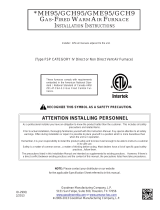
Figure 3. 90+ Upflow Converted for Horizontal Installation (Horizontal Right)
Figure 4. 90+ Upflow Converted for Horizontal Installation (Horizontal Left)
OrangeWire
Pressure Switch
Grey
Tubing
5" x 2" Drain
Trap Assembly
1/4" Vinyl
Cap
30" Soft
Tubing
PVCTee
50" Soft Tubing
Looped to Provide
a Drain Trap
3" to 2"
Reducer
(Optional)
PVC Reducer
Bushing
1/2" Barbed Fitting
(3/4" Barb for 3" Vent)
1/2" Vinyl
Cap
Soft Tubing
1/4" Vinyl Cap
Grey
Tubing
5" x 2" Drain
Trap Assembly
30" Soft
Tubing
PVC Tee
50" Soft Tubing
Looped to Provide
a Drain Trap
3" to 2"
Reducer
(Optional)
Reducer
Bushing
1/2" Barbed
Fitting
Alternative
for
Horizontal
Vent
Pressure
Switch
Orange Wire
hole located in the left side of the cabinet
wrapper. NOTE: A downward slope must
be maintained on the tube as it is routed
through the furnace (when the furnace is
in the horizontal position).
8. Assemble the 5” tall end of the hard “J” tube
to the end of the soft tube located outside of
the furnace. Secure the connection using
one of the 7/8” hose clamps supplied with
the installation kit.
9. Assemble the 30” piece of soft tubing re-
moved from the factory installed “J” tube
drain trap to the 2” tall end of the new “J”
tube drain trap. Secure the connection with
the second 7/8” hose clamp.
NOTE: To avoid condensate freezing in the
drain trap assembly and tubing, insulate
around the drain trap assembly and all tubing
located in unconditioned space.
Specifications & illustrations subject to change
without notice or incurring obligations (07/15).
O’Fallon, MO, © Nortek Global HVAC LLC 2015.
All Rights Reserved.
/