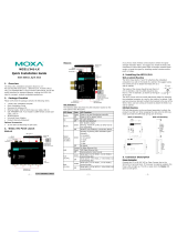
Moxa UC-8410A Series Quick setup guide

Type
Quick setup guide

Moxa UC-8410A Series embedded computers offer versatile communication capabilities with 8 configurable serial ports, 3 Ethernet ports, and support for wireless modules. They provide reliable data acquisition and transmission in industrial automation, transportation, and energy applications, making them ideal for remote monitoring, data logging, and industrial control.

Moxa UC-8410A Series embedded computers offer versatile communication capabilities with 8 configurable serial ports, 3 Ethernet ports, and support for wireless modules. They provide reliable data acquisition and transmission in industrial automation, transportation, and energy applications, making them ideal for remote monitoring, data logging, and industrial control.

P/N: 1802084100012
*1802084100012*
UC-8410A
Quick Installation Guide
Version 3.0, November 2020
Technical Support Contact Information
www.moxa.com/support
Moxa Americas:
Toll
-free: 1-888-669-2872
Tel:
1-714-528-6777
Fax:
1-714-528-6778
Moxa China (Shanghai office):
Toll
-free: 800-820-5036
Tel:
+86-21-5258-9955
Fax:
+86-21-5258-5505
Moxa Europe:
Tel:
+49-89-3 70 03 99-0
Fax:
+49-89-3 70 03 99-99
Moxa Asia-Pacific:
Tel:
+886-2-8919-1230
Fax:
+886-2-8919-1231
Moxa India:
Tel:
+91-80-4172-9088
Fax:
+91-80-4132-1045
2020 Moxa Inc. All rights reserved.
- 2 -
Overview
The UC-8410A Series of dual-core embedded computers support a rich
variety of communication interfaces and come with 8 RS-232/422/485
serial ports, 3 Ethernet ports, 1 PCIe mini slot for a wireless module (not
for the -NW model), 4 digital input channels, 4 digital output channels, 1
SD card slot, 1 mSATA socket, and 2 USB 2.0 hosts. The computer's
built-in 8 GB eMMC and 1 GB DDR3 SDRAM give you sufficient memory to
run your applications, while the SD slot and mSATA socket provide you
the flexibility to expand the data storage capacity.
Package Checklist
1 UC-8410A embedded computer
Wall-mounting kit
DIN-rail mounting kit
Ethernet cable: RJ45 to RJ45 cross-over cable, 100 cm
CBL-4PINDB9F-100: 4-pin pin header to DB9 female console port
cable, 100 cm
Quick installation guide (printed)
Warranty card
Please notify your sales representative if any of the above items are
missing or damaged.
Panel Layout
Refer to the following figures for the panel layouts.
Front View
NOTE
The
-
NW model is not provided with the antenna connectors and
SIM card socket. However, all models come with a cover.
Rear View
- 3 -
Left-side View
Installing the UC-8410A
Wall or Cabinet
The two metal brackets included with the UC-8410A can be used to attach
it to a wall or the inside of a cabinet. Using two screws per bracket, first
attach the brackets to the bottom of the UC-8410A.
These four screws are included
in the wall-mounting kit. Refer
to the right figure for the
detailed specifications.
Next, use two screws per bracket to attach the UC-8410A to a wall or
cabinet.
included in the wall-mounting
kit and must be purchased
separately. Refer to the detailed
specifications on the right.
Head Type: round or pan
Head Diameter: >4.5 mm
Length: >4 mm
Thread Size: M3 x 0.5 mm
- 4 -
DIN Rail
The UC-8410A comes with a DIN-rail mounting kit, which includes a black
plate, a silver DIN-rail mounting plate, and six screws. Follow these steps
for the installation.
Find the two screw holes on the bottom side of the computer.
Place the black plate and fasten with two screws.
Use another four screws to fasten the DIN-rail mounting plate.
Refer to the figure on the right
for the screw specifications.
- 5 -
To install the computer
on a DIN-rail, follow
these steps:
Step 1Insert the
upper lip of the DIN-rail
kit into the mounting
rail.
Step 2Press the
UC-8410A computer
towards the mounting
rail until it snaps into
place.
To remove the computer
from the DIN-rail, follow
these steps:
Step 1Pull down the
latch on the DIN-rail kit
with a screwdriver.
Steps 2 & 3Slightly
pull the computer
forward and lift up to
remove it from the
mounting rail.
Connector Description
Power Connector
Connect the 12-48 VDC power line to the UC-8410A’s terminal block. The
Ready LED will glow a steady green color after 30 to 60 seconds have
passed.
Grounding the UC-8410A
Grounding and wire routing help limit the effects of noise due to
electromagnetic interference (EMI). Run the ground connection from the
ground screw to the grounding surface prior to connecting the power.
ATTENTION
This product is intended to be mounted
on to a well-grounded
mounting surface, such as a metal panel.
- 6 -
SG: The Shielded Ground (sometimes called
Protected Ground) contact is the
right
most
contact
on the 3-pin power terminal block
connector when viewed from the angle
shown here. Connect the SG wire to an
appropriate grounded metal surface.
An
additional ground connector is provided just
above the power terminal block, which you
can use for grounding
protection.
Ethernet Port
The 3 10/100
/1000 Mbps
Ethernet ports (LAN 1, LAN 2,
and LAN3) use RJ45 connectors.
PIN
10/100
Mbps
1000
Mbps
1
ETx+
TRD(0)+
2
ETx-
TRD(0)-
3
ERx+
TRD(1)+
4
---
TRD(2)+
5
---
TRD(2)-
6
ERx-
TRD(1)-
7
---
TRD(3)+
8
---
TRD(3)-
Serial Port
The 8 serial ports (P1 to P8) use RJ45 connectors. Each port can be
configured by software as RS-232, RS-422, or RS-485. The pin
assignments are shown in the following table:
Pin
RS-232
RS-422/RS-485-4W
RS-485
1
DSR
2
RTS
TXD+
3
GND
GND
GND
4
TXD
TXD-
5
RXD
RXD+
Data+
6
DCD
RXD-
Data-
7
CTS
8
DTR
Digital Inputs and Digital Outputs
The UC-8410A has 4 digital output channels and 4 digital input channels.
Refer to the UC-8410A Hardware User's Manual for detailed pinouts and
wiring.
SD/mSATA
The UC-8410A comes with a SD card slot and an mSATA socket for
storage expansion.
- 7 -
To replace or install the SD card, or to install an mSATA card, follow these
steps:
1. Use a screwdriver to remove the screws on the rear and side panels of
the cover over the mSATA socket.
2. Remove the cover to access the SD-card slot and the mSATA socket.
3. Push the SD card in gently to release it and remove the SD card to
insert a new one in the socket. Make sure your SD card has been
securely inserted.
4. Insert the mSATA card into the socket, and then fasten the screws.
Please note that the mSATA card is NOT included in the product
package and must be purchased separately. Standard mSATA card
types have been tested with the UC-8410A computer and have been
found to work normally. For additional details, refer to the UC-8410A
hardware manual.
- 8 -
Console Port
The serial console port is a 4-pin pin-header RS-232 port that is located
below the SD card socket. Use a screwdriver to remove the two screws
holding the cover to the embedded computer’s housing. The port is used
for the serial console terminal, which is useful for viewing boot-up
messages. Use the CBL-4PINDB9F-100 cable included with the
UC-8410A-LX to connect a PC to the UC-8410A’s serial console port. For
details on configuring the UC-8410A-LX, refer to the Connecting the
UC-8410A Computer to a PC section.
Reset Button
Self-Diagnostic: The red LED will start blinking when you press the reset
button. Keep the button pressed until the green LED lights up for the first
time, and then release the button to enter diagnostic mode.
Reset to Factory Default: The red LED will start blinking when you press
the reset button. Keep the button pressed until the green LED lights up for
the second time and then release the button to start the reset to factory
default process.
USB
The UC-8410A supports 2 USB 2.0 hosts for external storage expansion.
Installing the Wireless Modules (not for the NW
model)
Instructions for installing the Wi-Fi and cellular modules on the UC-8410A
computer are available in the Installing the Wireless Modules section of
the UC-8410A Hardware User's Manual.
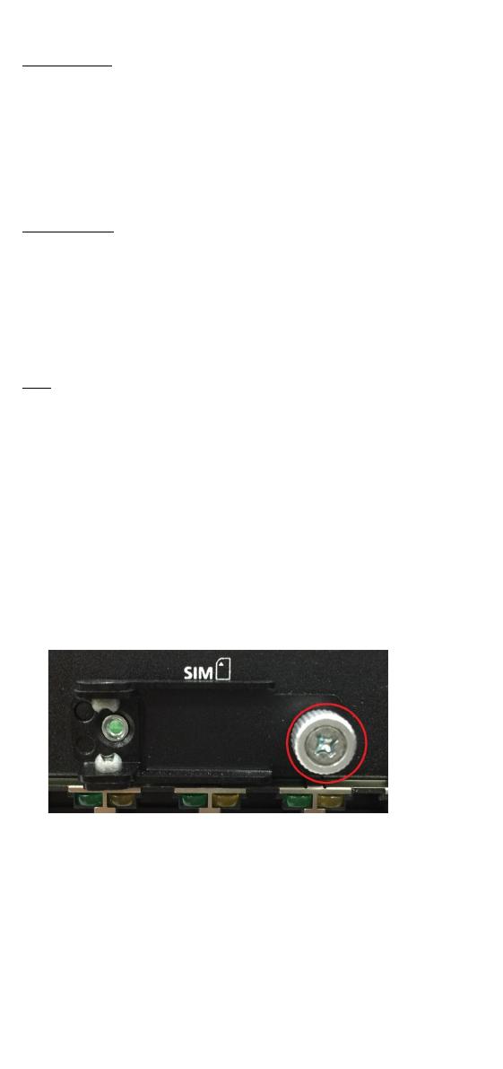
Installing the SIM Card
Follow these steps to install the SIM card for the cellular module.
1. Unfasten the screw on the SIM card holder cover located on the front
panel of the computer.
- 9 -
2. Insert the SIM card into the slot. Make sure you insert the card in the
direction indicated above the card slot.
3. Close the cover and fasten the screw.
Powering on the UC-8410A Computer
To power on the UC-8410A, connect a terminal block to power jack
converter to the UC-8410A’s DC terminal block (located on the left rear
panel), and then connect the power adapter. Note that the Shielded
Ground wire should be connected to the right most pin of the terminal
block. It takes approximately 30 seconds for the system to boot up. Once
the system is ready, the Ready LED will light up.
Connecting the UC-8410A Computer to a PC
There are two ways to connect the UC-8410A to a PC: (1) through the
serial console port (2) using Telnet over the network. The COM settings
for the serial console port are: Baudrate=115200 bps, Parity=None,
Data bits=8, Stop bits =1, Flow Control=None.
ATTENTION
Remember to choose the “VT100” terminal type. Use the
CBL
-4PINDB9F-
100 cable included with the product to connect a
PC to the UC-8410A’s serial console port.
- 10 -
To use Telnet, you will need to know the UC-8410A’s IP address and
netmask. The default LAN settings are shown below. For initial
configuration, you may find it convenient to use a cross-over Ethernet
cable to connect directly from the PC to the UC-8410A.
Default IP Address
Netmask
LAN 1
192.168.3.127
255.255.255.0
LAN 2
192.168.4.127
255.255.255.0
LAN 3
192.168.5.127
255.255.255.0
Once the UC-8410A is powered on, the Ready LED will light up, and a
login page will open. Use the following default Login name and Password
to proceed.
Linux:
Login: moxa
Password: moxa
Configuring the Ethernet Interface
Linux Models
If you are using the console cable for a first-time configuration of the
network settings, use the following commands to edit the
interfaces
file:
#ifdown a
//Disable LAN1/LAN2/LAN3 interface first, before you
reconfigure the LAN settings. LAN 1 = eth0, LAN 2= eth1, LAN
3= eth2
#vi /etc/network/interfaces
//check the LAN interface first//
After the boot settings of the LAN interface have been modified, use the
following command to activate the LAN settings with immediate effect:
#sync; ifup –a
NOTE
Refer to the
UC-8410A Series Linux Software User’s Manual for
additional configuration information.
  • Page 1 1
  • Page 2 2
  • Page 3 3
  • Page 4 4
  • Page 5 5
  • Page 6 6
  • Page 7 7
  • Page 8 8
  • Page 9 9
  • Page 10 10

Moxa UC-8410A Series Quick setup guide

Type
Quick setup guide

Moxa UC-8410A Series embedded computers offer versatile communication capabilities with 8 configurable serial ports, 3 Ethernet ports, and support for wireless modules. They provide reliable data acquisition and transmission in industrial automation, transportation, and energy applications, making them ideal for remote monitoring, data logging, and industrial control.

Ask a question and I''ll find the answer in the document

Finding information in a document is now easier with AI