Lexmark 5500 User manual
- Category
- Scanner Transparancy Adapters
- Type
- User manual
This manual is also suitable for


Edition: March 2004
The following paragraph does not apply to any country where such provisions are inconsistent with local law:
LEXMARK INTERNATIONAL, INC. PROVIDES THIS PUBLICATION “AS IS” WITHOUT WARRANTY OF ANY KIND,
EITHER EXPRESS OR IMPLIED, INCLUDING, BUT NOT LIMITED TO, THE IMPLIED WARRANTIES OF
MERCHANTABILITY OR FITNESS FOR A PARTICULAR PURPOSE. Some states do not allow disclaimer of express or
implied warranties in certain transactions; therefore, this statement may not apply to you.
This publication could include technical inaccuracies or typographical errors. Changes are periodically made to the
information herein; these changes will be incorporated in later editions. Improvements or changes in the products or the
programs described may be made at any time.
Comments may be addressed to Lexmark International, Inc., Department D22A/032-2, 740 West New Circle Road,
Lexington, Kentucky 40550, U.S.A or e-mail at ServiceInfoAndTraining@Lexmark.com. Lexmark may use or distribute any
of the information you supply in any way it believes appropriate without incurring any obligation to you. You can purchase
additional copies of publications related to this product by calling 1-800-553-9727. In other countries, contact your point of
purchase.
Lexmark and Lexmark with diamond design are trademarks of Lexmark International, Inc., registered in the United States
and/or other countries.
Other trademarks are the property of their respective owners.
©
2003, 2004 Lexmark International, Inc.
All rights reserved.
UNITED STATES GOVERNMENT RIGHTS
This software and any accompanying documentation provided under this agreement are commercial computer software
and documentation developed exclusively at private expense.
U.S.A. P/N 12G9319
4036-402

Table of contents iii
4036-402
Table of contents
Safety information . . . . . . . . . . . . . . . . . . . . . . . . . . . . . . . . . . . . . . . . . . . . . . . . . . . . . v
Preface . . . . . . . . . . . . . . . . . . . . . . . . . . . . . . . . . . . . . . . . . . . . . . . . . . . . . . . . . . . . . . viii
Definitions . . . . . . . . . . . . . . . . . . . . . . . . . . . . . . . . . . . . . . . . . . . . . . . . . . . . . . . . . . . . . . . . . . . viii
General information . . . . . . . . . . . . . . . . . . . . . . . . . . . . . . . . . . . . . . . . . . . . . . . . . . . . . . . . . . . . . 1-1
Overview . . . . . . . . . . . . . . . . . . . . . . . . . . . . . . . . . . . . . . . . . . . . . . . . . . . . . . . . . . . . . . . . . . . 1-1
Maintenance approach . . . . . . . . . . . . . . . . . . . . . . . . . . . . . . . . . . . . . . . . . . . . . . . . . . . . . . . . 1-2
Service guidelines . . . . . . . . . . . . . . . . . . . . . . . . . . . . . . . . . . . . . . . . . . . . . . . . . . . . . . . . 1-2
Maintenance tools . . . . . . . . . . . . . . . . . . . . . . . . . . . . . . . . . . . . . . . . . . . . . . . . . . . . . . . . 1-2
Product specifications . . . . . . . . . . . . . . . . . . . . . . . . . . . . . . . . . . . . . . . . . . . . . . . . . . . . . . . . . 1-3
Theory of operation . . . . . . . . . . . . . . . . . . . . . . . . . . . . . . . . . . . . . . . . . . . . . . . . . . . . . . . . . . . 1-4
System description . . . . . . . . . . . . . . . . . . . . . . . . . . . . . . . . . . . . . . . . . . . . . . . . . . . . . . . 1-4
Mechanical operation . . . . . . . . . . . . . . . . . . . . . . . . . . . . . . . . . . . . . . . . . . . . . . . . . . . . . 1-5
Acronyms . . . . . . . . . . . . . . . . . . . . . . . . . . . . . . . . . . . . . . . . . . . . . . . . . . . . . . . . . . . . . . . . . . 1-6
Diagnostic information . . . . . . . . . . . . . . . . . . . . . . . . . . . . . . . . . . . . . . . . . . . . . . . . . . . . . . . . . . 2-1
Start . . . . . . . . . . . . . . . . . . . . . . . . . . . . . . . . . . . . . . . . . . . . . . . . . . . . . . . . . . . . . . . . . . . . . . 2-1
Error codes . . . . . . . . . . . . . . . . . . . . . . . . . . . . . . . . . . . . . . . . . . . . . . . . . . . . . . . . . . . . . . . . . 2-2
MFD controller errors . . . . . . . . . . . . . . . . . . . . . . . . . . . . . . . . . . . . . . . . . . . . . . . . . . . . . 2-2
Scanner errors . . . . . . . . . . . . . . . . . . . . . . . . . . . . . . . . . . . . . . . . . . . . . . . . . . . . . . . . . . 2-4
Symptoms and service checks . . . . . . . . . . . . . . . . . . . . . . . . . . . . . . . . . . . . . . . . . . . . . . . . . . 2-6
The power does not come on . . . . . . . . . . . . . . . . . . . . . . . . . . . . . . . . . . . . . . . . . . . . . . . 2-6
Scan module does not move to the lock position . . . . . . . . . . . . . . . . . . . . . . . . . . . . . . . . 2-6
Scan module does not move to the home position . . . . . . . . . . . . . . . . . . . . . . . . . . . . . . . 2-7
Scan module does not move to the flatbed position . . . . . . . . . . . . . . . . . . . . . . . . . . . . . . 2-7
System hangs while booting or displays erratic behavior . . . . . . . . . . . . . . . . . . . . . . . . . . 2-7
Image does not appear . . . . . . . . . . . . . . . . . . . . . . . . . . . . . . . . . . . . . . . . . . . . . . . . . . . . 2-8
Large jitter . . . . . . . . . . . . . . . . . . . . . . . . . . . . . . . . . . . . . . . . . . . . . . . . . . . . . . . . . . . . . . 2-8
Irregular movement . . . . . . . . . . . . . . . . . . . . . . . . . . . . . . . . . . . . . . . . . . . . . . . . . . . . . . . 2-8
Image unclear . . . . . . . . . . . . . . . . . . . . . . . . . . . . . . . . . . . . . . . . . . . . . . . . . . . . . . . . . . . 2-8
Strange sound generated (flatbed) . . . . . . . . . . . . . . . . . . . . . . . . . . . . . . . . . . . . . . . . . . . 2-9
Frequent paper jam, double feed, or skew . . . . . . . . . . . . . . . . . . . . . . . . . . . . . . . . . . . . . 2-9
Strange sound generated (ADF) . . . . . . . . . . . . . . . . . . . . . . . . . . . . . . . . . . . . . . . . . . . . . 2-9
Clearing a paper jam . . . . . . . . . . . . . . . . . . . . . . . . . . . . . . . . . . . . . . . . . . . . . . . . . . . . . . . . . 2-10
Repair information . . . . . . . . . . . . . . . . . . . . . . . . . . . . . . . . . . . . . . . . . . . . . . . . . . . . . . . . . . . . . . 3-1
Parts replacement . . . . . . . . . . . . . . . . . . . . . . . . . . . . . . . . . . . . . . . . . . . . . . . . . . . . . . . . . . . . 3-1
Adjustments . . . . . . . . . . . . . . . . . . . . . . . . . . . . . . . . . . . . . . . . . . . . . . . . . . . . . . . . . . . . . . . . 3-2
Scanner calibration . . . . . . . . . . . . . . . . . . . . . . . . . . . . . . . . . . . . . . . . . . . . . . . . . . . . . . . 3-2
Hard disk drive refresh . . . . . . . . . . . . . . . . . . . . . . . . . . . . . . . . . . . . . . . . . . . . . . . . . . . . 3-4
Code update procedure . . . . . . . . . . . . . . . . . . . . . . . . . . . . . . . . . . . . . . . . . . . . . . . . . . . 3-4

iv Service Manual
4036-402
Removals . . . . . . . . . . . . . . . . . . . . . . . . . . . . . . . . . . . . . . . . . . . . . . . . . . . . . . . . . . . . . . . . . . . 3-5
Charge-coupled device (CCD) card screws . . . . . . . . . . . . . . . . . . . . . . . . . . . . . . . . . . . . . 3-5
ADF assembly . . . . . . . . . . . . . . . . . . . . . . . . . . . . . . . . . . . . . . . . . . . . . . . . . . . . . . . . . . . 3-6
ADF upper cover . . . . . . . . . . . . . . . . . . . . . . . . . . . . . . . . . . . . . . . . . . . . . . . . . . . . . . . . . 3-8
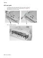
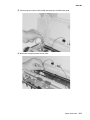
ADF upper guide . . . . . . . . . . . . . . . . . . . . . . . . . . . . . . . . . . . . . . . . . . . . . . . . . . . . . . . . . 3-9
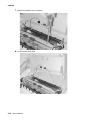
ADF lower guide . . . . . . . . . . . . . . . . . . . . . . . . . . . . . . . . . . . . . . . . . . . . . . . . . . . . . . . .3-10
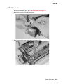
ADF drive motor . . . . . . . . . . . . . . . . . . . . . . . . . . . . . . . . . . . . . . . . . . . . . . . . . . . . . . . . .3-13
ADF controller card . . . . . . . . . . . . . . . . . . . . . . . . . . . . . . . . . . . . . . . . . . . . . . . . . . . . . .3-15
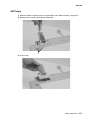
ADF hinge . . . . . . . . . . . . . . . . . . . . . . . . . . . . . . . . . . . . . . . . . . . . . . . . . . . . . . . . . . . . . 3-17
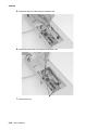
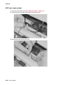
Paper input tray . . . . . . . . . . . . . . . . . . . . . . . . . . . . . . . . . . . . . . . . . . . . . . . . . . . . . . . . . 3-18
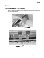
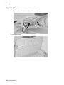
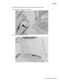
Internal ADF CCD subassembly . . . . . . . . . . . . . . . . . . . . . . . . . . . . . . . . . . . . . . . . . . . . 3-20
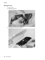
ADF pick pad . . . . . . . . . . . . . . . . . . . . . . . . . . . . . . . . . . . . . . . . . . . . . . . . . . . . . . . . . . . 3-24
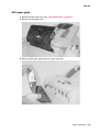
ADF pick roller . . . . . . . . . . . . . . . . . . . . . . . . . . . . . . . . . . . . . . . . . . . . . . . . . . . . . . . . . . 3-26
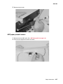
ADF paper present sensor . . . . . . . . . . . . . . . . . . . . . . . . . . . . . . . . . . . . . . . . . . . . . . . . . 3-27
ADF cover open sensor . . . . . . . . . . . . . . . . . . . . . . . . . . . . . . . . . . . . . . . . . . . . . . . . . . . 3-28
User interface . . . . . . . . . . . . . . . . . . . . . . . . . . . . . . . . . . . . . . . . . . . . . . . . . . . . . . . . . . 3-30
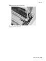
Upper housing . . . . . . . . . . . . . . . . . . . . . . . . . . . . . . . . . . . . . . . . . . . . . . . . . . . . . . . . . .3-32
Flatbed lamp assembly . . . . . . . . . . . . . . . . . . . . . . . . . . . . . . . . . . . . . . . . . . . . . . . . . . . 3-34
Flatbed CCD optical unit . . . . . . . . . . . . . . . . . . . . . . . . . . . . . . . . . . . . . . . . . . . . . . . . . . 3-36
Multifunction device (MFD) controller card cage . . . . . . . . . . . . . . . . . . . . . . . . . . . . . . . . 3-38
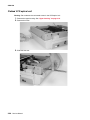
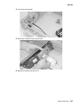
Hard disk drive, MFD controller card, power distribution card,
memory DIMM, and cooling fan . . . . . . . . . . . . . . . . . . . . . . . . . . . . . . . . . . . . . . . . . 3-41
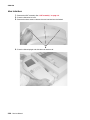
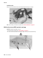
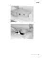
Main scanner card . . . . . . . . . . . . . . . . . . . . . . . . . . . . . . . . . . . . . . . . . . . . . . . . . . . . . . . 3-42
Connector locations . . . . . . . . . . . . . . . . . . . . . . . . . . . . . . . . . . . . . . . . . . . . . . . . . . . . . . . . . . . . . 4-1
Locations . . . . . . . . . . . . . . . . . . . . . . . . . . . . . . . . . . . . . . . . . . . . . . . . . . . . . . . . . . . . . . . . . . . 4-1
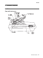
Paper path and sensors . . . . . . . . . . . . . . . . . . . . . . . . . . . . . . . . . . . . . . . . . . . . . . . . . . . . 4-1
Internal view . . . . . . . . . . . . . . . . . . . . . . . . . . . . . . . . . . . . . . . . . . . . . . . . . . . . . . . . . . . . . 4-2
Connectors . . . . . . . . . . . . . . . . . . . . . . . . . . . . . . . . . . . . . . . . . . . . . . . . . . . . . . . . . . . . . . . . . 4-3
Main scanner card . . . . . . . . . . . . . . . . . . . . . . . . . . . . . . . . . . . . . . . . . . . . . . . . . . . . . . . .4-3
Power distribution card . . . . . . . . . . . . . . . . . . . . . . . . . . . . . . . . . . . . . . . . . . . . . . . . . . . .4-3
Low voltage power supply . . . . . . . . . . . . . . . . . . . . . . . . . . . . . . . . . . . . . . . . . . . . . . . . . . 4-4
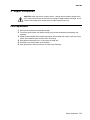
Preventive maintenance . . . . . . . . . . . . . . . . . . . . . . . . . . . . . . . . . . . . . . . . . . . . . . . . . . . . . . . . . 5-1
Cleaning . . . . . . . . . . . . . . . . . . . . . . . . . . . . . . . . . . . . . . . . . . . . . . . . . . . . . . . . . . . . . . . . . . . 5-1
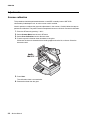
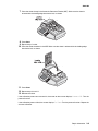
Moving the scanner . . . . . . . . . . . . . . . . . . . . . . . . . . . . . . . . . . . . . . . . . . . . . . . . . . . . . . . . . . . 5-3
Parts catalog . . . . . . . . . . . . . . . . . . . . . . . . . . . . . . . . . . . . . . . . . . . . . . . . . . . . . . . . . . . . . . . . . . . . 6-1
How to use this parts catalog . . . . . . . . . . . . . . . . . . . . . . . . . . . . . . . . . . . . . . . . . . . . . . . . . . . 6-1
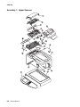
Assembly 1: Upper Scanner . . . . . . . . . . . . . . . . . . . . . . . . . . . . . . . . . . . . . . . . . . . . . . . . . . 6-2
Assembly 2: Lower scanner. . . . . . . . . . . . . . . . . . . . . . . . . . . . . . . . . . . . . . . . . . . . . . . . . . . 6-4
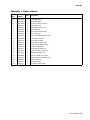
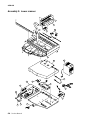
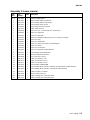
Assembly 3: Miscellaneous . . . . . . . . . . . . . . . . . . . . . . . . . . . . . . . . . . . . . . . . . . . . . . . . . . . 6-6
Index . . . . . . . . . . . . . . . . . . . . . . . . . . . . . . . . . . . . . . . . . . . . . . . . . . . . . . . . . . . . . . . .I-1
Part number index . . . . . . . . . . . . . . . . . . . . . . . . . . . . . . . . . . . . . . . . . . . . . . . . . . . . .I-5

Safety information v
4036-402
Safety information
• The safety of this product is based on testing and approvals of the original design and specific
components. The manufacturer is not responsible for safety in the event of use of unauthorized
replacement parts.
• The maintenance information for this product has been prepared for use by a professional
service person and is not intended to be used by others.
• There may be an increased risk of electric shock and personal injury during disassembly and
servicing of this product. Professional service personnel should understand this and take
necessary precautions.
• CAUTION: When you see this symbol, there is a danger from hazardous voltage in the
area of the product where you are working. Unplug the product before you begin, or use
caution if the product must receive power in order to perform the task.
Consignes de sécurité
• La sécurité de ce produit repose sur des tests et des
agréations portant sur sa conception d'origine et sur des composants particuliers. Le fabricant
n'assume aucune responsabilité concernant la sécurité en cas d'utilisation de pièces de
rechange non agréées.
• Les consignes d'entretien et de réparation de ce produit s'adressent uniquement à un personnel
de maintenance qualifié.
• Le démontage et l'entretien de ce produit pouvant présenter certains risques électriques, le
personnel d'entretien qualifié devra prendre toutes les précautions nécessaires.
• ATTENTION : Ce symbole indique la présence d'une tension dangereuse dans la partie
du produit sur laquelle vous travaillez. Débranchez le produit avant de commencer ou
faites preuve de vigilance si l'exécution de la tâche exige que le produit reste sous
tension.
Norme di sicurezza
• La sicurezza del prodotto si basa sui test e sull'approvazione del progetto originale e dei
componenti specifici. Il produttore non è responsabile per la sicurezza in caso di sostituzione
non autorizzata delle parti.
• Le informazioni riguardanti la manutenzione di questo prodotto sono indirizzate soltanto al
personale di assistenza autorizzato.
• Durante lo smontaggio e la manutenzione di questo prodotto,
il rischio di subire scosse elettriche e danni alla persona è più elevato. Il personale di assistenza
autorizzato deve, quindi, adottare le precauzioni necessarie.
• ATTENZIONE: Questo simbolo indica la presenza di tensione pericolosa nell'area del
prodotto. Scollegare il prodotto prima di iniziare o usare cautela se il prodotto deve
essere alimentato per eseguire l'intervento.

vi Service Manual
4036-402
Sicherheitshinweise
• Die Sicherheit dieses Produkts basiert auf Tests und Zulassungen des ursprünglichen Modells
und bestimmter Bauteile. Bei Verwendung nicht genehmigter Ersatzteile wird vom Hersteller
keine Verantwortung oder Haftung für die Sicherheit übernommen.
• Die Wartungsinformationen für dieses Produkt sind ausschließlich für die Verwendung durch
einen Wartungsfachmann bestimmt.
• Während des Auseinandernehmens und der Wartung des Geräts besteht ein zusätzliches
Risiko eines elektrischen Schlags und körperlicher Verletzung. Das zuständige Fachpersonal
sollte entsprechende Vorsichtsmaßnahmen treffen.
• ACHTUNG: Dieses Symbol weist auf eine gefährliche elektrische Spannung hin, die in
diesem Bereich des Produkts auftreten kann. Ziehen Sie vor den Arbeiten am Gerät
den Netzstecker des Geräts, bzw. arbeiten Sie mit großer Vorsicht, wenn das Produkt
für die Ausführung der Arbeiten an den Strom angeschlossen sein muß.
Pautas de Seguridad
• La seguridad de este producto se basa en pruebas y aprobaciones del diseño original y
componentes específicos. El fabricante no es responsable de la seguridad en caso de uso de
piezas de repuesto no autorizadas.
• La información sobre el mantenimiento de este producto está dirigida exclusivamente al
personal cualificado de mantenimiento.
• Existe mayor riesgo de descarga eléctrica y de daños personales durante el desmontaje y la
reparación de la máquina. El personal cualificado debe ser consciente de este peligro y tomar
las precauciones necesarias.
• PRECAUCIÓN: este símbolo indica que el voltaje de la parte del equipo con la que está
trabajando es peligroso. Antes de empezar, desenchufe el equipo o tenga cuidado si,
para trabajar con él, debe conectarlo.
Informações de Segurança
• A segurança deste produto baseia-se em testes e aprovações do modelo original e de
componentes específicos. O fabricante não é responsável pela segunrança, no caso de uso de
peças de substituição não autorizadas.
• As informações de segurança relativas a este produto destinam-se a profissionais destes
serviços e não devem ser utilizadas por outras pessoas.
• Risco de choques eléctricos e ferimentos graves durante a desmontagem e manutenção deste
produto. Os profissionais destes serviços devem estar avisados deste facto e tomar os
cuidados necessários.
• CUIDADO: Quando vir este símbolo, existe a possível presença de uma potencial
tensão perigosa na zona do produto em que está a trabalhar. Antes de começar,
desligue o produto da tomada eléctrica ou seja cuidadoso caso o produto tenha de
estar ligado à corrente eléctrica para realizar a tarefa necessária.

Safety information vii
4036-402
Informació de Seguretat
• La seguretat d'aquest producte es basa en l'avaluació i aprovació del disseny original i els
components específics.
El fabricant no es fa responsable de les qüestions de
seguretat si s'utilitzen peces de recanvi no autoritzades.
• La informació pel manteniment d’aquest producte està orientada exclusivament a professionals
i no està destinada
a ningú que no ho sigui.
• El risc de xoc elèctric i de danys personals pot augmentar durant el procés de desmuntatge i de
servei d’aquest producte. El personal professional ha d’estar-ne assabentat i prendre
les mesures convenients.
• PRECAUCIÓ: aquest símbol indica que el voltatge de la part de l'equip amb la qual
esteu treballant és perillós. Abans de començar, desendolleu l'equip o extremeu les
precaucions si, per treballar amb l'equip, l'heu de connectar.

viii Service Manual
4036-402
Preface
This manual contains maintenance procedures for service personnel. It is divided into the following
chapters:
1. General information contains a general description of the product and the maintenance
approach used to repair it. Special tools and test equipment are listed in this chapter, as well as
general environmental and safety instructions.
2. Diagnostic information contains an error indicator table, symptom tables, and service checks
used to isolate failing field replaceable units (FRUs).
3. Repair information provides instructions for making product adjustments and removing and
installing FRUs.
4. Connector locations uses illustrations to identify the connector locations and test points on the
product.
5. Preventive maintenance contains the lubrication specifications and recommendations to
prevent problems.
6. Parts catalog contains illustrations and part numbers for individual FRUs.
Definitions
Note: A note provides additional information.
Warning: A warning identifies something that might damage the product hardware or software.
CAUTION: A caution identifies something that might cause a servicer harm.
CAUTION: When you see this symbol, there is a danger from hazardous voltage in the
area of the product where you are working. Unplug the product before you begin, or use
caution if the product must receive power in order to perform the task.

General information 1-1
4036-402
1. General information
Overview
The Lexmark X5500 (4036-402) MFP option is a multifunction solution that offers integrated print,
copy, fax, and color network-scanning capabilities for increased small workgroup productivity. The
option is easy to use and provides low-cost access to key office functions, including fax from
workstation, network color copying, scanning, and electronic document routing.
Give your document to the scanner, and in a few steps, it scans to the network and delivers it
wherever, to whomever you want. With this scanner, inefficient trips to the mailroom, copier, fax
machine, and to your workstation are a thing of the past.
Features
Ease of use
The user interface on the front of the scanner looks like a panel on a copier with standard phone keys
added. The operating steps follow the same procedure as that of a copier or fax machine.
Digital copier and full-function fax machine
When the scanner is connected to a Lexmark MFP, it performs convenient digital copying. When
connected to a telephone line, the scanner performs a full fax function - to send and to receive faxes.
Network scanning
The scanner uses two color charge-coupled devices (CCD) when scanning. Through a network port
at the rear of the scanner, the product is able to do network scanning.
Duplex scanning through the Auto Document Feeder (ADF)
To increase workgroup productivity, the scanner uses a single pass duplex unit within the ADF. The
scan speed limit is 35 ppm at 300 dpi resolution. The auto document feeder can hold up to 50 pages
at one time.

1-2 Service Manual
4036-402
Maintenance approach
This manual is for maintenance engineers. It describes the maintenance areas, installation,
disassembly, and the main troubleshooting guides.
Read this manual thoroughly to obtain comprehensive knowledge about the scanner before servicing
the unit.
Service guidelines
CAUTION: The combined scanner and automatic document feeder weighs 25.7 kg (56.6 Ib) and
requires at least two people to lift it safely. Anytime you move or lift the scanner, make sure you have
enough people to help you.
CAUTION: Before disassembling the scanner, make sure the power supply cord is disconnected
from the power outlet. Do not remove or install the connectors on the scanner with the power supply
turned ON.
• Use care not to drop small parts or screws inside the unit when disassembling and
reassembling.
• Do not pull the connector cable when disconnecting it. Hold the connector.
• When carrying the scanning head unit, put it in an anti-static bag.
• Keep the document glass platen surface clean with a dry clean lint free cloth.
Maintenance tools
The following table describes the tools necessary for the maintenance of this scanner.
In addition there is a special calibration sheet that is included with certain FRUs and must be used
after the installation. It can also be ordered separately.
Name Description
Flathead screwdriver Idler pulley module screw
Phillips screwdriver (magnetic) Nominal No.2 M3, M4
Nut driver 6 mm
Digital voltmeter With 0.01 V range
Chip puller Puller for main scanner card chip

General information 1-3
4036-402
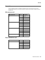
Product specifications
The scanner is designed to meet the following product specifications:
Scanner type Flatbed scanner with ADF built in
ADF capacity 50 sheets 75g/m² (20 lb)
Media weight 60 g/m² (16 lb) to 120 g/m² (32 lb)
Optical resolution Flatbed: 600 x 600 dpi
ADF: 600 x 600 dpi
Scan speed 19 ppm for black and white text or mixed input
27 ppm for color input, single page scanning
25 ppm for color input, duplex
Scan method Color charge-coupled device (CCD)
Light source Cold cathode fluorescent lamp (CCFL)
Scan area ADF and flatbed: Max. 297 mm x 432 mm (11.7 x 17 in.)
Display 640 x 480 color VGA touch screen
Image types 1-, 8-, 24-bit with image processing
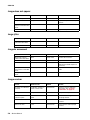
Scan accuracy Flatbed ADF
Leading edge <-1 ~ +2 mm <2 ~ +2 mm
Side edge <-1 ~ +2 mm <2 ~ +2 mm
Skew <1 mm <2 mm
Magnification rate tolerance
(horizontal and vertical)
-1.0% ~ +1.0% -1.5% ~ +1.5%
Physical dimension Height: 419 mm (16.5 in.), measuring to top of ADF feed tray
Width: 660mm (26 in.)
Depth: 686mm (27 in.
Weight 25.7 kg (56.5 lb)
Memory 128MB DRAM
Hard disk drive 10GB or greater
Fax modem 33.6 bps
Paper feed Face up long edge feed (LEF)

1-4 Service Manual
4036-402
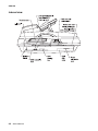
Theory of operation
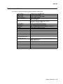
System description
The Lexmark X5500 is a duplex scanner option which can synchronously scan both the top and
bottom of a document in color. The major system components include a main scanner control card,
an automatic document feeder, flatbed, two optical CCD modules (one in ADF, one in flatbed), a user
interface with a touch screen panel and a multifunction device controller cage located within the base
of the scanner. The MFD controller cage includes a MFD controller card to process all jobs
performed on the X5500 and communicates with the rest of the scanner, a hard disk drive containing
the operational code for the system and providing memory for processing jobs, and a power
distribution card. An external power supply provides 5, 12, and 24 V dc to the entire scanner system.
The following figure shows the system block diagram.

General information 1-5
4036-402
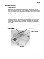
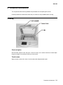
Mechanical operation
Flatbed operation
When scanning, place the document on the flatbed glass platen, the flatbed optical unit/carrier
moves across the underside of the glass, and scans the document. A charge-coupled device (CCD)
mounts to the carrier and optically reads the image from the page. The carrier is driven by a 2-phase
stepping motor which moves the carriage at 1/600 inch each step.
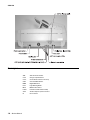
Auto Document Feeder operation
When using the Auto Document Feeder (ADF) mechanism, a page is fed into the ADF by a pick roller
and through the ADF by feed rollers. A separation pick pad located opposite the pick rollers is used to
properly feed the pages one at a time when placed on the input tray. The flatbed optical unit/carrier is
positioned to the far left so when the paper passes through the ADF, the bottom of the page is
scanned by the flatbed CCD. The home position sensor detects when the carrier is in the proper
position for ADF scanning. In addition, an ADF cover open sensor detects when the upper ADF
assembly is open or closed into proper operating position. The scanner cannot operate when this
sensor is open.
While the page is fed through and scanned from the bottom via the flatbed CCD, the top of the page
is simultaneously scanned via a CCD unit positioned within the ADF unit. As the page feeds between
the two CCD units, the page discharges to the exit tray on the left side of the ADF.

1-6 Service Manual
4036-402
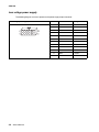
Acronyms
ADF Auto Document Feeder
CCD Charge-Coupled Device
CCFL Cold Cathode Fluorescent Lamp
CDB Command Data Blocks
DMM Digital Multimeter
LED Light Emitting Diode
MFD Multifunction Device
PCBA Printed Circuit Board Assembly
SCSI Small Computer System Interface
UI User Interface

Diagnostic information 2-1
4036-402
2. Diagnostic information
CAUTION: When you see this symbol, there is a danger from hazardous voltage in the
area of the product where you are working. Unplug the product before you begin, or use
caution if the product must receive power in order to perform the task.
Start
This chapter describes two methods to solve the operational problems. The first relies on the scanner
internal diagnostics to report error codes. The second uses troubleshooting techniques to isolate the
problem. In many cases, the internal error codes will help you to locate the source of the problem
quickly. If no error codes are reported, or if the error codes do not locate the source of the problem,
see “Symptoms and service checks” on page 2-6.

2-2 Service Manual
4036-402
Error codes
MFD controller errors
MFD controller errors are errors detected by the MFD (multifunction device) controller card within the
MFD cage pertaining to electronic cards. All MFD controller cage errors are posted to the user
interface touch screen along with audible beep codes and LED codes. During the Power-On Self Test
procedure, errors detected cause a number of audible beeps to be produced three times. The
corresponding LED pattern continuously displays on the controller card until the system is powered
down. Use the following tables to read the beep/LED codes and follow the recommended repair
action.
There are four pairs of LEDs along the rear edge of the MFD controller card. The LEDs are visible
from the rear of the scanner though holes in the metal card cage panel. The LED patterns in the table
below depict which LEDs are visible from the rear of the scanner.
Error message
Number
of beeps
LED pattern
(on= , off= )
Action
Error: 21 - Modem not found 2 Modem on the MFD
controller card is not found.
Replace the MFD controller
card.
Error: 22 - PCI Bus failure 2 Replace the MFD controller
card.
Error: 23 - Internal Scanner
Card Failure
2 The 1394 controller on the
MFD controller card has
failed. Replace the MFD
controller card.

Diagnostic information 2-3
4036-402
Error: 24 - Serial port failure 2 Problem with TTY/Serial
Port. Replace the MFD
controller card.
Error: 28 - Problem with the
CPU
2 Replace the MFD controller
card.
Note: Error message not
displayed. Only beep code
and LED patterns are
generated for error 31.
3 No hard disk drive found.
Check connections to the
hard disk drive and
associated cables for
continuity. Check power
going to the hard disk drive.
Replace the power
distribution card if no power
is present. If power is
present, replace the hard
disk drive.
Note: Error message not
displayed. Only beep code
and LED patterns are
generated for error 32.
3 Corrupt hard disk drive.
Replace or reformat the
hard disk drive. See “Hard
disk drive refresh” on
page 3-4.
Error: 34 - Hard Drive failure 3 There was an error writing to
the hard disk drive. Replace
or reformat the hard disk
drive. See “Hard disk drive
refresh” on page 3-4.
Note: Error message not
displayed. Only beep code
and LED patterns are
generated for error 51.
5 No memory found.
The memory DIMM was not
detected or not functioning.
Replace the memory DIMM.
Error: 52 - Not enough
memory
5 The memory DIMM was
found, but not enough
memory is present. Replace
the memory DIMM.
Error: 71 - User Interface
failure
7 A problem was detected with
the user interface. Check the
connection of all cables
connecting the UI to the
MFD controller card. If
cables are okay, replace the
user interface. If problem
persists, replace the MFD
controller card.
Error message
Number
of beeps
LED pattern
(on= , off= )
Action

2-4 Service Manual
4036-402
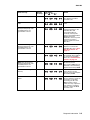
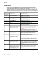
Scanner errors
Scanner errors are errors detected within the scanner mechanism and auto document feeder
assembly. When these errors occur, the user interface touch screen posts 1900 Service Error
along with a number of flashes of the flatbed CCD lamp (the flash sequence is repeated ten times).
See the following table for an explanation of each error code and the corrective action to resolve the
problem.
Number of CCD
lamp flashes
Error message Description and action
1 Oasis 1 SDRAM Failure SDRAM failure in the flatbed.
Replace the main scanner card.
2 Oasis 2 SDRAM Failure SDRAM failure in the ADF.
Replace the main scanner card.
3 CPU SDRAM Failure Replace the main scanner card.
4 Flatbed A/D Dark Calibration
Error
Replace the flatbed optical unit assembly. If problem
persists, replace the main scanner card.
5 ADF A/D Dark Calibration Error Replace the ADF internal subassembly. If problem persists,
replace the main scanner card.
6 Flatbed Home sensor failure or
flatbed motor failure. Please verify
that the flatbed is not locked.
Home sensor failure.
Check that the flatbed is not locked. See “Moving the
scanner” on page 5-3 for information about the locking
mechanism.
Check the flatbed motor, belt, and home position sensor for
proper operation. Replace any defective parts. If no
defective parts are found, replace the main scanner card.
7 Flatbed Lamp Failure Check the flatbed optical unit for proper connection.
Replace the flatbed lamp or optical unit, if necessary.
8 ADF Lamp Failure Check the ADF internal subassembly for proper connection.
Replace the ADF optical unit if necessary.
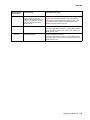
9 Note: Various messages may
appear on the user interface.
ADF paper jam.
Check the paper feed actuator to verify it is not obstructed
and is moving properly. The easiest way to inspect the
actuator is from under the ADF assembly. If the actuator is
working properly, replace the ADF internal subassembly.
10 Note: Various messages may
appear on the user interface.
ADF cover open.
Check the ADF cover open sensor for proper connection.
Check that the ADF upper cover closes completely and that
the actuator passes through the ADF cover open sensor
when closed.
11 ADF cable may be loose. Please
turn off the system and check that
all cables are installed and all
screws tight. If this reoccurs, this
may be an ADF home sensor
failure or ADF motor failure.
Scanner communication error.
Check the ADF to flatbed cable. Make sure it is properly
connected. If the problem persists, replace the ADF
assembly.

Diagnostic information 2-5
4036-402
12 Flatbed may be locked. Please
check to make sure that the
flatbed is unlocked and restart the
system. If the flatbed is already
unlocked, this may be a Home
Sensor Failure.
Unlock the flatbed. See “Moving the scanner” on
page 5-3 for information about the locking mechanism.
If the flatbed is unlocked and the problem persists, check
the connection of the cable to the flatbed optical unit.
Replace the optical unit if necessary.
No beeps SCSI command not supported Scanner communication error.
Check the 1394 cable connections. If the problem remains,
replace the main scanner card. If the persists, replace the
MFD controller card.
No beeps Invalid field in CDB Scanner communication error.
Check the 1394 cable connections. If the problem remains,
replace the main scanner card. If the persists, replace the
MFD controller card.
Number of CCD
lamp flashes
Error message Description and action

2-6 Service Manual
4036-402
Symptoms and service checks
The tables in this section provide detailed troubleshooting information.
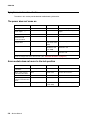
The power does not come on
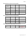
Scan module does not move to the lock position
Cause Relevant unit Check * Action
Unplugged from outlet None Visual check Insert the ac plug into the outlet.
AC power unplugged at
power supply
LVPS Visual check Insert the ac cable into power
supply.
Power switch is OFF None Visual check Turn the power switch on.
Power supply power
distribution card
connection failure
None Visual check Connect the connector.
Power supply output
voltage failure
LVPS Check the LVPS
(+5V +12V, +24V,
GND)
Replace the power supply.
Power distribution card Power distribution card Check the power
distribution card
(+5V, GND)
Replace the failed power
distribution card.
MFD controller card MFD controller card None If problem still exists, replace MFD
controller card.
* Check explains how to check the failed item. To do a visual check, observe the part. To do a tester check,
check the voltage levels of the relevant units. (See “Connector locations” on page 4-1.)
Cause Relevant unit Check Action
Home position sensor
card failure
Flatbed optical unit Visual check Replace the flatbed optical unit.
Motor—main scanner
card connection failure
None Visual check Connect the connector.
Motor failure Carrier motor Visual check Replace the flatbed optical unit.
Power supply—main
scanner card connection
failure
None Visual check Connect the connector.
Power supply fails. Power supply Tester check
(+24V, GND)
Replace the power supply.
Page is loading ...
Page is loading ...
Page is loading ...
Page is loading ...
Page is loading ...
Page is loading ...
Page is loading ...
Page is loading ...
Page is loading ...
Page is loading ...
Page is loading ...
Page is loading ...
Page is loading ...
Page is loading ...
Page is loading ...
Page is loading ...
Page is loading ...
Page is loading ...
Page is loading ...
Page is loading ...
Page is loading ...
Page is loading ...
Page is loading ...
Page is loading ...
Page is loading ...
Page is loading ...
Page is loading ...
Page is loading ...
Page is loading ...
Page is loading ...
Page is loading ...
Page is loading ...
Page is loading ...
Page is loading ...
Page is loading ...
Page is loading ...
Page is loading ...
Page is loading ...
Page is loading ...
Page is loading ...
Page is loading ...
Page is loading ...
Page is loading ...
Page is loading ...
Page is loading ...
Page is loading ...
Page is loading ...
Page is loading ...
Page is loading ...
Page is loading ...
Page is loading ...
Page is loading ...
Page is loading ...
Page is loading ...
Page is loading ...
Page is loading ...
Page is loading ...
Page is loading ...
Page is loading ...
Page is loading ...
Page is loading ...
Page is loading ...
Page is loading ...
Page is loading ...
Page is loading ...
Page is loading ...
Page is loading ...
Page is loading ...
-
 1
1
-
 2
2
-
 3
3
-
 4
4
-
 5
5
-
 6
6
-
 7
7
-
 8
8
-
 9
9
-
 10
10
-
 11
11
-
 12
12
-
 13
13
-
 14
14
-
 15
15
-
 16
16
-
 17
17
-
 18
18
-
 19
19
-
 20
20
-
 21
21
-
 22
22
-
 23
23
-
 24
24
-
 25
25
-
 26
26
-
 27
27
-
 28
28
-
 29
29
-
 30
30
-
 31
31
-
 32
32
-
 33
33
-
 34
34
-
 35
35
-
 36
36
-
 37
37
-
 38
38
-
 39
39
-
 40
40
-
 41
41
-
 42
42
-
 43
43
-
 44
44
-
 45
45
-
 46
46
-
 47
47
-
 48
48
-
 49
49
-
 50
50
-
 51
51
-
 52
52
-
 53
53
-
 54
54
-
 55
55
-
 56
56
-
 57
57
-
 58
58
-
 59
59
-
 60
60
-
 61
61
-
 62
62
-
 63
63
-
 64
64
-
 65
65
-
 66
66
-
 67
67
-
 68
68
-
 69
69
-
 70
70
-
 71
71
-
 72
72
-
 73
73
-
 74
74
-
 75
75
-
 76
76
-
 77
77
-
 78
78
-
 79
79
-
 80
80
-
 81
81
-
 82
82
-
 83
83
-
 84
84
-
 85
85
-
 86
86
-
 87
87
-
 88
88


Lexmark 5500 User manual
- Category
- Scanner Transparancy Adapters
- Type
- User manual
- This manual is also suitable for
Ask a question and I''ll find the answer in the document
Finding information in a document is now easier with AI