Page is loading ...

Convertible
Dishwasher
This Base Manual covers general information
Refer to individual Technical Sheet
for information on specific models
This manual includes, but is
not limited to the following:
Service
This manual is to be used by qualified appliance
technicians only. Maytag does not assume any
responsibility for property damage or personal
injury for improper service procedures done by
an unqualified person.
16026945
March 2006
MDC4650AW*

2 16026945 ©2006 Maytag Services
Important Notices for Servicers and Consumers
Maytag will not be responsible for personal injury or property damage from improper service procedures. Pride and
workmanship go into every product to provide our customers with quality products. It is possible, however, that
during its lifetime a product may require service. Products should be serviced only by a qualified service technician
who is familiar with the safety procedures required in the repair and who is equipped with the proper tools, parts,
testing instruments and the appropriate service information. IT IS THE TECHNICIANS RESPONSIBLITY TO
REVIEW ALL APPROPRIATE SERVICE INFORMATION BEFORE BEGINNING REPAIRS.
!
WARNING
To avoid risk of severe personal injury or death, disconnect power before working/servicing on appliance to avoid
electrical shock.
To locate an authorized servicer, please consult your telephone book or the dealer from whom you purchased this
product. For further assistance, please contact:
Customer Service Support Center
CAIR Center in Canada ........................................... 1-800-688-2002
Amana Canada Product ........................................... 1-866-587-2002
Customer Assistance Information Resource (CAIR) Center
Brand Web Site Telephone Number
Amana ................................WWW.AMANA.COM ...................................... 1-800-843-0304
Hoover ................................WWW.HOOVER.COM .................................... 1-800-944-9200
Jennair................................WWW.JENNAIR.COM .................................... 1-800-536-6247
Maytag ...............................WWW.MAYTAG.COM .................................... 1-800-688-9900
Recognize Safety Symbols, Words, and Labels
DANGER!
DANGER—Immediate hazards which WILL result in severe personal injury or death.
WARNING!
WARNING—Hazards or unsafe practices which COULD result in severe personal injury or death.
CAUTION!
CAUTION—Hazards or unsafe practices which COULD result in minor personal injury, product or property
damage.
Important Information

©2006 Maytag Services 16026945 3
Important Information
Table of Contents
Important Information
Important Notices for Servicers and Consumers .... 2
Recognize Safety Symbols, Words, and Labels ... 2
Table of Contents.................................................. 3
Important Safety Information
General Information ............................................... 4
Related Publications ............................................. 4
General Precautions and Warnings....................... 4
General Information
Model Identification ............................................... 7
Service ................................................................. 7
Parts and Accessories.......................................... 7
Extended Service Plan.......................................... 7
Model Nomenclature ............................................. 8
Troubleshooting
Will Not Fill........................................................... 9
Overflows .............................................................. 9
Poor Water Circulation.......................................... 9
Poor Washability .................................................10
Will Not Drain ......................................................10
Continues to Drain ...............................................10
Poor Drying .........................................................10
Water Leaks ........................................................11
Noise ...................................................................11
Will Not Start or Program .....................................11
Will Not Fill..........................................................11
Will Not Wash .....................................................12
Will Not Drain ......................................................12
Will Not Dry .........................................................12
Manual Function Test ..........................................12
Field Service Test ................................................12
Testing Procedures
Electrical Test Equipment ....................................13
Appliance Test Meter ...........................................13
Continuity Testing ................................................13
Digital Test Meter.................................................13
Voltage Checks ...................................................14
Motor Test Cord ...................................................14
Grounding Polarity ...............................................14
Electrical Tests
Water Valve .........................................................15
Wax Motor Check - Dispenser.............................15
Wax Motor Check - Vent .....................................16
Disassembly Procedures
Technical Sheet ...................................................17
Foil Bottom..........................................................17
Wood Top ............................................................18
Toe Panel ............................................................18
Cabinet ................................................................18
Faucet .................................................................19
Retainer - Faucet Coupler ....................................19
Casters................................................................19
Inner Door Panel ..................................................20
Detergent / Rinse Dispenser Mech. and Res. ......20
Wax Motor Detergent / Rinse Dispenser ..............21
Vent.....................................................................21
Door Latch & Switch Holder Assembly.................22
PC Board.............................................................22
Upper Rack Removal ...........................................23
Tub Wheels .........................................................23
Door Latch Strike .................................................23
Control Panel .......................................................23
Outer Door ...........................................................24
Door Hinge And Support ......................................24
Door Spring ..........................................................25
Door Spring And Component Replacement...........25
Manifold ...............................................................26
Docking Station ...................................................26
Top Wash Arm .....................................................26
Lower Wash Arm .................................................27
Air Water Inlet .....................................................27
Door Gasket ........................................................28
Float ....................................................................28
Heating Element ..................................................29
Thermostats ........................................................30
Water Valve .........................................................30
Checking Valve Operation ....................................31
Turbidity Sensor...................................................31
Drain Pump .........................................................32
Wash Motor Assembly ........................................32
Appendix A
Installation Instructions ....................................... A-1
Appendix B
Use And Care ..................................................... B-1

4 16026945 ©2006 Maytag Services
Important Safety Information
WARNING
!
To avoid personal injury or death from improper
servicing, make sure you read and understand the
descriptions and meaning of various safety symbols,
words and labels used in this manual, before
attempting any procedures described in the manual.
Failure to understand and comply with safety
information may result in severe personal injury or
death.
General Information
This Service Manual describes the operation,
disassembly, troubleshooting, and repair of Maytag
®
Dishwashers. It is intended for use by authorized
servicers who troubleshoot and repair these units.
NOTE: It is assumed that users of this manual are
familiar with the use of tools and equipment used
to troubleshoot and repair electrical, and
mechanical systems; and understand the
terminology used to describe and discuss them.
Related Publications
This is a base service manual, covering a range of
similar models. It is intended to be used in conjunction
with the Parts Manual and Technical Sheet covering
specific model being serviced.
General Precautions and Warnings
• Dispose of discarded appliance and shipping or
packing material properly.
• Do not allow children to play in or on dishwasher.
• Do not abuse, sit, stand or play on door or racks of a
dishwasher.
• Use only detergents and rinse agents recommended for
use in a dishwasher.
• Store dishwasher detergent and rinse agents out of the
reach of children.
• If the dishwasher drains into a food disposer, make
sure disposer is completely empty before running
dishwasher.
• Repairs should be done by a qualified technician.
• Do not tamper with controls.
• Do not touch the heating element during or immediately
after use.
• Load sharp knives with the handles up to reduce the
risk of cut-type injuries or damaging seal.
To avoid risk of personal injury or death due to
electrical shock:
• Grounding wires and wires colored like grounding
wires are NOT to be used as current carrying
conductors.
• Standard accepted color coding for ground wires
is green or green with a yellow stripe.
• Grounding wires should not be removed from
individual components while servicing, unless
component is to be removed and replaced.
• Replace all removed grounding wires before
completing service.
WARNING
!
To avoid death, severe personal injury, fire or
electrical shock when using dishwasher observe
the following:
• Observe all local codes and ordinances.
• Disconnect electrical power to dishwasher before
servicing.
• Connect dishwasher to a grounded metal,
permanent wiring system.
• DO NOT ground to gas line.
• DO NOT ground to cold water pipe if pipe is
interrupted by plastic, non-metallic gaskets, or
other insulating (non-conducting) materials.
• Check with a qualified electrician if you are not
sure this appliance is properly grounded.
• This dishwasher is designed to operate on
regular house current (120 V, 60 Hz). Use a
circuit equipped with a 15 ampere fuse or circuit
breaker. Use a 20 ampere fuse if dishwasher is
connected with a food waste disposer.
• Under certain conditions, hydrogen gas may be
produced in a hot water system that has not
been used for 2 weeks or more. HYDROGEN
GAS IS EXPLOSIVE. If hot water system has
not been used for such a period, before using
dishwasher, turn on all hot water faucets and let
water flow from each for several minutes. This will
release any accumulated hydrogen gas.
HYDROGEN GAS IS FLAMMABLE. Do not
smoke or use an open flame during this time.
• Do not store or use combustible materials,
gasoline or other flammable vapors and liquids in
the vicinity of this or any other appliance.
• Do not wash plastic items unless marked
"dishwasher safe" or the equivalent. If not
marked, check with manufacturer for
recommendations. Items that are not dishwasher
safe may melt and create a potential fire hazard.
• To avoid entrapment and/or suffocation, remove
door or door latch mechanism from any
dishwasher that is discarded or not in use.
WARNING
!

©2006 Maytag Services 16026945 5
Important Safety Information
PRECAUCIÓN:
Desconecte la
energía eléctrica
antes de darie
servicio.
ATENCIÓN:
Solamente use
conductores de
cobre. Use cables de
suministro adecuados
para 75° (167°F).
CAUTION:
Disconnect electrical power
before servicing.
ATTENTION:
Use copper conductors only.
Use supply wires suitable for 75°C (167°F).
ATTENTION:
Débrancher de
l'alimentation électrique avant tout dépannage.
ATTENTION:
Utiliser des conducteurs en
cuivre uniquement. Utiliser des fils
d'alimentation pouvant supporter une
température de 75°C (167°F).
GROUNDING: This unit must
be grounded in accordance with local
and/or national electric codes.
WARNING: The heating
element, drain pump, harness clip,
dispenser mount, and water valve are
intentionally not grounded and may
present a risk of electrical shock only
during servicing. Discharge motor
capacitior before servicing. Failure to
follow these instructions can result in
death, serious injury, fire, or electrical
shock.
MISE Á LA TERRE:
Cet appareil
doit être relié à la terre conformément aux
codes électriques locaux et/ou nationaux.
AVERTISSEMENT:
La résistance,
la pompe de vidange, l'attache du hamais, la
monture de distributeur et l'électrovanne ne
sont pas reliés à la terre intentionnellement et
peuvent présenter des risques d'électrocution
uniquement en cas d'intervention de service
aprés-vente. Décharger le condensateur
avant toute intervention. Le non-respect de
ces consignes peut entrainer la mort, des
blessures graves, l'incendie ou l'électrocution.
CONEXIÓN A TIERRA: Esta
unidad debe estar conectada a tierra de
acuerdo con los códigos eléctricos locales y
nacionales.
ADVERTENCIA: El elemento calentador,
la bomba de drenado, el sujetador del arnés,
el montaje del surtidor y la válvula de
agua están sin conectar a tierra
intencionalmente podrían presentar un riesgo
de descargas eléctricas cuando se les da
servicio solamente. El no seguir estas
instrucciones podría causar la muerte, lesiones
graves, incendios o descargas eléctricas.

6 16026945 ©2006 Maytag Services
W
A
R
N
I
N
G
:
D
i
s
c
o
n
n
e
c
t
p
o
w
e
r
b
e
f
o
r
e
s
e
r
v
i
c
i
n
g
.
E
l
e
c
t
r
o
n
i
c
c
o
n
t
r
o
l
i
s
e
e
r
g
i
z
e
d
a
t
a
l
l
t
i
m
e
s
u
n
t
i
l
p
o
w
e
r
i
s
d
i
s
c
o
n
n
e
c
t
e
d
.
C
a
p
a
c
i
t
o
r
s
o
n
c
o
n
t
r
o
l
m
a
y
r
e
m
a
i
n
a
c
t
i
v
e
a
f
t
e
r
e
l
e
c
t
r
i
c
a
l
p
o
w
e
r
i
s
d
i
s
c
o
n
n
e
c
t
e
d
.
F
a
i
l
u
r
e
t
o
f
o
l
l
o
w
t
h
e
s
e
i
n
t
r
u
c
t
i
o
n
s
c
a
n
r
e
s
u
l
t
i
n
d
e
a
t
h
,
s
e
r
i
o
u
s
i
n
j
u
r
y
,
f
i
r
e
,
o
r
e
l
e
c
tr
i
c
a
l
s
h
o
c
k
.
A
D
V
E
R
T
E
N
C
I
A
:
D
e
s
c
o
n
e
c
t
e
l
a
e
n
e
r
g
í
a
n
t
e
s
d
e
d
a
r
l
e
s
e
r
v
i
c
i
o
.
E
l
c
o
n
t
r
o
l
e
l
e
c
t
r
ó
n
i
c
o
e
s
t
á
e
n
e
r
g
i
z
a
d
o
t
o
d
o
e
l
t
i
e
m
p
o
h
a
s
t
a
q
u
e
s
e
d
e
s
c
o
n
e
c
t
a
l
a
e
n
e
r
g
í
a
.
L
o
s
c
a
p
a
c
i
t
o
r
e
s
d
e
l
c
o
n
t
r
o
l
p
o
d
r
í
a
n
p
e
r
m
a
n
e
c
e
r
a
c
t
i
v
o
s
d
e
s
p
u
é
s
d
e
d
e
s
c
o
n
e
c
t
a
r
l
a
e
n
e
r
g
í
a
e
l
é
c
t
r
i
c
a
.
E
l
n
o
s
e
g
u
i
r
e
s
t
a
s
i
n
s
t
r
u
c
c
i
o
n
e
s
p
o
d
r
í
c
a
u
s
a
r
l
a
m
u
e
r
t
e
,
l
e
s
i
o
n
e
s
g
r
a
v
e
s
,
i
n
c
e
n
d
i
o
s
o
d
e
s
c
a
r
g
a
s
e
l
é
c
t
r
i
c
a
s
.
A
V
E
R
T
I
S
S
E
M
E
N
T
:
D
é
b
r
a
n
c
h
e
r
a
v
a
n
t
t
o
u
t
e
in
t
e
r
v
e
n
t
io
n
.
L
a
c
o
m
m
a
n
d
e
é
l
e
c
t
r
o
n
i
q
u
e
e
s
t
c
o
n
s
t
a
m
m
e
n
t
s
o
u
s
t
e
n
s
i
o
n
à
m
o
i
n
s
q
u
e
l
'
a
p
p
a
r
e
i
l
n
e
s
o
i
t
d
é
b
r
a
n
c
h
é
.
L
e
s
c
o
n
d
e
n
s
a
t
e
u
r
s
d
e
l
a
c
o
m
m
a
n
d
e
p
e
u
v
e
n
t
r
e
s
t
e
r
s
o
u
s
t
e
n
s
i
o
n
u
n
e
f
o
i
s
l
'
a
p
p
a
r
e
i
l
d
é
b
r
a
n
c
h
é
.
L
e
n
o
n
-
r
e
s
p
e
c
t
d
e
c
e
s
c
o
n
s
i
g
n
e
s
p
e
u
t
e
n
t
r
a
î
n
e
r
la
m
o
r
t
,
d
e
s
b
l
e
s
s
u
r
e
s
g
r
a
v
e
s
,
l
'
i
n
c
e
n
d
i
e
o
u
l
'
é
l
e
c
t
r
o
c
u
t
i
o
n
.
Important Safety Information
WARNING:
Disconnect power before servicing. Electronic control is energized at all times until
power is disconnected. Capacitors on control may remain active after electrical power is disconnected.
Failure to follow these instructions can result in death, serious injury, fire, or electrical shock.
ADVERTENCIA:
Desconecte la energí antes de darle servicio. El control electrónico está
energizado todo el tiempo hasta que se desconecta la energía. Los capacitores del control podrían
permanecer activos después de desconectar la energía eléctrica. El no seguir estas instrucciones
podrí causar la muerte, lesiones graves, incendios o descargas eléctricas.
AVERTISSEMENT:
Débrancher avant toute intervention. La commande électronique est
constamment sous tension à moins que l'appareil ne soit débranché. Les condensateurs de la
commande peuvent rester sous tension une fois l'appareil débranché. Le non-respect de ces consignes
peut entraîner la mort, des blessures graves, l'incendie ou l' électrocution.

General Information
©2006 Maytag Services 16026945 7
Model Identification
Complete registration card and promptly return. If
registration card is missing:
• For Amana product call 1-800-843-0304 or visit the
Web Site at www.amana.com
• For Maytag product call 1-800-688-9900 or visit the
Web Site at www.maytag.com
• For Jenn-Air product call 1-800-536-6247 or visit the
Web Site at www.jennair.com
• For Hoover product call 1-800-944-9200 or visit the
Web Site at www.hoover.com
• For product in Canada call 1-866-587-2002 or visit the
Web Sites at www.amana.com or www.maytag.com or
www.jennair.com
When contacting Maytag service, provide product
information located on rating plate. Record the following:
Model Number: ___________________
Manufacturing Number: ___________________
Serial or S/N Number: ___________________
Date of purchase: ___________________
Dealer’s name and address: ___________________
Serial Label is located inside the upper left side of the
door opening.
Service
Keep a copy of sales receipt for future reference or in
case warranty service is required. To locate an authorized
servicer:
• For Amana product call 1-800-628-5782 or visit the
Web Site at www.amana.com
• For Maytag/Jenn-Air product call 1-800-462-9824 or
visit the Web Site at www.maytag.com or
www.jennair.com
• For Hoover product call 1-800-944-9200 or visit the
Web Site at www.hoover.com
• For product in Canada call 1-866-587-2002 or visit the
Web Sites at www.amana.com or www.maytag.com or
www.jennair.com
Warranty service must be performed by an authorized
servicer. We also recommend contacting an authorized
servicer, if service is required after warranty expires.
Parts and Accessories
To order parts and accessories for your product:
• For Amana product call 1-877-232-6771 or visit the
Web Site at www.amana.com
• For Maytag/Jenn-Air product call 1-800-462-9824 or
visit the Web Site at www.maytag.com or
www.jennair.com
• For product inCanada call 1-866-587-2002 or visit the
Web Sites at www.amana.com or www.maytag.com or
www.jennair.com
Extended Service Plan
We offer long-term service protection for this new
appliance.
• Asure™ Extended Service Plan is specially designed
to supplement Amana’s strong warranty. This plan
covers parts, labor, and travel charges.
Call 1-866-232-6244 for information.
• Dependability Plus
SM
Extended Service Plan is
specially designed to supplement Maytag’s and
Jenn-Air’s strong warranty. This plan covers parts,
labor, and travel charges.
Call 1-800-925-2020 for information.

General Information
8 16026945 ©2006 Maytag Services

©2006 Maytag Services 16026945 9
Will Not Fill
Water Access Valve
Check to determine if the valve is turned on and water is
available to the Dishwasher. Check water pressure.
Circuit Breaker/Fuse
Check for tripped breaker or blown fuse. Reset or replace
as necessary.
Door Latch
Check door switches for continuity. With door switches
engaged, no continuity, replace switch.
Float
Check float position. If in the up position, check for
obstruction or disengagement from the Float Switch Arm.
Float Switch
If the float is in the down position, check the switch for
continuity. If no continuity, replace the Float Switch.
Water Valve
Check Solenoid for continuity. No continuity, replace
Water Valve. Check Inlet Screen for restrictions. Clean
screen or replace Water Valve as necessary. (See section
5).
Wiring/Electrical Connections
Check for loose or frayed wire terminal connections.
Check for broken wire within harness. Repair or replace
as necessary.
Float
Ensure that the Float isn't stuck in the down position.
Check for sediment buildup. Clean and/or replace as
necessary.
Float Switch Actuator Lever
Check the actuator lever on the bracket. It must be able
to move freely. Repair or replace as necessary. (See
section 5).
Float Switch
Check Float Switch for continuity with the Float in the up
position. If continuity is present and Float moves up and
down freely, replace Float Switch.
!
WARNING
To avoid risk of electrical shock, personal injury, or death, disconnect electrical power source to unit and discharge
capacitor through a 10,000 ohm resistor before attempting to service, unless test procedures require power to be
connected. Ensure all ground wires are connected before certifying unit as repaired and/or operational.
CA UTION
!
Units covered in this manual are polarized. Reversing polarity of a unit or any of its components will cause
damage. To avoid reversing polarity, any wires disconnected or removed during service must be reconnected to the
same location. To ensure wires are reconnected to the proper location, tag or otherwise mark the wires before
disconnecting or removing.
Poor Water Circulation
Water Level - Too Low
Normal water fill should be at level depicted by arrows.
Pump Assembly
Check assembly for obstructions or restricted movement
of parts. Repair and/or replace parts as necessary.
Overflows
Water Valve
Check that water continues to flow when electrical power
is turned off. If the water continues to flow without
electrical power, replace Water Valve.
NOTE: Low water pressure can result in failure of the
Water Valve to close properly.
Troubleshooting

10 16026945 ©2006 Maytag Services
Filters
Check for blockage of Strainer, Over Pressure Filter.
Repair as necessary.
Poor Washability
Spray Arms
Check all Spray Arms for blockage of water ports or
cracks. Check for proper rack loading to avoid interference
with Spray Arms during wash action. Check for proper
sealing, fastening, and movement of Spray Arms. Repair
as necessary.
Filters
Check for blockage of Strainer, Primary Filter, and Filter
Support. Repair as necessary.
Detergent Cup Cover
Check spring hinge operation of Detergent Cup Cover.
Repair as necessary.
Detergent Cup
Check operation of Detergent Cup Assembly, Wax Motor,
Actuator, Linkage, and Cover Latch. Repair and/or replace
parts as necessary. Note: For testing of Wax Motor, see
Section 2.
Rinse Dispenser
Check level of rinse aid in reservoir. Check rinse aid
dispenser setting.
Will Not Drain
Inadequate Drainage
Check Drain Pump for proper operation. Check the drain
pipe connections and repair as needed. If draining into the
garbage disposal, check for unprocessed food waste at
drain hose connection to disposer. Clean out as needed.
Drain Hose
Check drain hose for kink or restrictions. Reroute or
remove any restriction of drain hose as needed.
Pump Assembly
Check pump assembly for obstructions or restricted
parts. Repair or replace parts as necessary.
Wiring/Electrical Connections
Check for loose or frayed wire terminal connections.
Check for broken wire within harness. Repair or replace
as necessary.
Troubleshooting
!
WARNING
To avoid risk of electrical shock, personal injury, or death, disconnect electrical power source to unit and discharge
capacitor through a 10,000 ohm resistor before attempting to service, unless test procedures require power to be
connected. Ensure all ground wires are connected before certifying unit as repaired and/or operational.
Continues To Drain
Control Board
Check Control Board for proper operation.
Wash Delivery System
Check manifold and Docking Station for good seal and no
leaks.
Poor Drying
Water Temperature
Check for low water temperature. Temperature should be
between 120 - 150 degrees Fahrenheit. If not, advise
consumer to adjust water heater setting. Encourage
consumer to purge water lines to the dishwasher area
prior to starting the dishwasher.
Cycle Options
Advise consumer use of options available on dishwasher
that improve drying. Options that improve drying are
Heated Dry, and 160° Wash.
Detergent
Check water hardness. Instruct consumer on detergent
usage, one teaspoon of detergent per grain of water
hardness.
Rinse Dispenser
Check level of rinse aid in reservoir. Check dispenser
setting under cap. Use "MAX" for hard water conditions.
Improper Rack Loading
Check how the consumer loads the dishes into the racks.
Improper loading of some types of dishes can trap water
which causes dishes not to dry.
Heating Element
Check load readings listed on Technical Sheet located
behind Toe Panel.

©2006 Maytag Services 16026945 11
Thermostat
Check mating surface of the High Limit Thermostat face
to surface of tub enclosure. Contact area must be flat.
Adjust the thermostat placement if necessary. See
Technical Sheet, located behind Toe Panel for thermostat
data.
Water Leaks
Installation
Check Dishwasher for proper leveling and squareness in
cabinet.
Door Alignment
Check proper alignment of Door Liner to Door Gasket.
Door Gasket
Check for torn or damaged Door Gasket. Repair or
replace as necessary.
Hoses
Check for loose hose clamps or hoses that leak. Tighten
hose clamps or replace hoses as needed.
Spray Arms / Manifold
Check for cracks and replace as necessary.
Detergent / Rinse Aid Dispenser Seal
Check Rinse Aid Dispenser Seal for proper positioning or
cracking. Reposition or replace as needed.
Water Valve
Check Water Valve body for damage and leaks. Replace if
necessary. Also, check plumbing connections to Water
Valve.
Wash Motor Assembly
Check for water leak between Pump Assembly and tub.
Drain Pump Assembly
Check Pump Assembly Housing for cracks. Check Drain
Pump "O" ring for leaks.
Troubleshooting
!
WARNING
To avoid risk of electrical shock, personal injury, or death, disconnect electrical power source to unit and discharge
capacitor through a 10,000 ohm resistor before attempting to service, unless test procedures require power to be
connected. Ensure all ground wires are connected before certifying unit as repaired and/or operational.
Noise
Banging
Check for loose Spray Arms. Check for dishes interfering
with Spray Arm rotation. See loading information in the
User's Guide at the end of this manual.
Hammering/Chattering
Check Water Valve for noise, low voltage, or high valve
coil resistance. Replace Water Valve if needed. Also,
check incoming water supply line for proper size and
pressure. Make sure the supply line is secured.
Grinding
Check for objects in Pump Assembly. If objects are
found, inspect Pump Assembly for damage. Repair as
needed.
Vibration
Check components for source of vibration. Adjust and/or
tighten as needed.
Will Not Start Or Program
Control Board
Check incoming voltage to Control Board.
Membrane Switch
Check for proper operation of Membrane Switch. See
membrane readings on the Technical Sheet located
behind toe panel.
NOTE: Make sure the pin connectors are making proper
contact with pins on the Control Board. If the
voltage is correct into the Control Board, and the
board will not activate, replace board.
Will Not Fill
Water Valve
Check Water Valve circuit. See Technical Sheet for water
valve data located behind toe panel.
NOTE: Make sure the pin connectors are making proper
contact with pins on the Control Board.

12 16026945 ©2006 Maytag Services
Will Not Wash
Wash Motor
Check Wash Motor circuit. See data listed on the
Technical Sheet, located behind Toe Panel.
Troubleshooting
!
WARNING
To avoid risk of electrical shock, personal injury, or death, disconnect electrical power source to unit and discharge
capacitor through a 10,000 ohm resistor before attempting to service, unless test procedures require power to be
connected. Ensure all ground wires are connected before certifying unit as repaired and/or operational.
Will Not Drain
Drain Motor
Check Drain Motor circuit. See data listed on the
Technical Sheet, located behind Toe Panel.
Will Not Dry
Vent Assembly
Check Vent Assembly for proper operation. Check Wax
Motor.
Heating Element
Check Heating Element circuit. See data listed on the
Technical Sheet, located behind Toe Panel.
Manual Function Test
See Technical Sheet, located behind Toe Panel.
Field Service Test
See Technical Sheet, located behind Toe Panel.

©2006 Maytag Services 16026945 13
Testing Procedures
Electrical Test Equipment
The equipment required to service these models depends
largely upon the condition encountered. Locating a
malfunction will often require the use of electrical testing
equipment such as:
Appliance Test Meter
Clamp-On Ammeter
Motor Test Cord
Appliance Test Meter
An Appliance Test Meter is a multi-purpose tester
combining an AC/DC voltage tester with a multi-range
ohmmeter.
The easiest means of testing electrical components is
"Continuity Testing" with an appliance meter. Continuity
is a complete or continuous path from one point in an
electrical circuit to another.
The obvious advantages of being able to check electrical
components and circuits without power applied is one of
the features of the Ohmmeter. Multiple ranges allow
accurate determination of resistances of both single
components and entire circuit paths. Resistance is
measured in "Ohms."
To avoid risk of personal injury or death due to
electrical shock:
Always be sure the power has been disconnected
before making resistance measurements. Failure to
do so will also result in damage to your meter!
Internal batteries provide all the power needed to
make resistance checks. They should be checked
at least once a year and replaced as needed.
Continuity Testing: is a process of eliminating electrical
components involved in a given function of the appliance,
until the inoperative part is found. By reviewing the list of
possible electrical problems under a given condition, and
then performing appropriate continuity checks of the parts
involved, you should be able to locate the electrical
component which is inoperative.
NOTE: When checking components or circuit paths for
continuity, external wiring should be disconnected to
eliminate false readings through external paths. Isolate
what you want to test.
Digital Test Meter
can be used to check for open
or closed circuits, measure
resistance, AC and DC volts,
and temperature.
Analog Test Meter
can be used to check for
open or closed circuits,
measure resistance, AC and
DC volts, and temperature.
WARNING
!

14 16026945 ©2006 Maytag Services
Voltage Checks
Generally, these checks will consist of taking readings
at the wall receptacle in order to determine the
availability of voltage to the product. Voltage checks on
individual components of a product are not
recommended due to the possibility of electrical shock.
Component part testing is best accomplished through
continuity checks with an Appliance Test Meter.
NOTE: Use of the meter on voltage higher than the
indicated range may cause permanent damage to the
meter. To prevent damage, first select highest range and
then lower the range for readings which fall within the
lower scale.
Clamp-On Ammeter
can be used to detect shorts.
Overloads on the circuit breaker
or fuse can be traced
to either the appliance
or circuit breaker by
checking the current
draw.
Each circuit in an appliance has a "Normal" current
draw, which is an indication of the performance of that
circuit. Current draw levels of less than or more than
normal give clues to possible malfunctions. The clamp-
on ammeter measures these circuits without breaking
the circuit by measuring the strength of the magnetic
field developed around each conductor. Current is read
by separating the conductors and clamping the jaws of
the ammeter around each conductor on which current is
read. Low amperage readings indicate problems, such
as damaged heating elements, etc. High amperage
readings indicate the unit being tested is operating under
an increased mechanical or electrical load.
NOTE: Overloads on a circuit breaker or fuse can be
traced to the product being tested or the circuit breaker
(or fuse) by checking the products current draw. If the
amperage reading is less than the breaker reading, the
breaker or fuse box is at fault.
Use of Ammeter on dishwasher:
1. Motor Current - the reading can be taken at the
leads on the motor start relay or at the male connec-
tor.
2. Heating Element Current - The reading can be
taken using either lead to the element.
Motor Test Cord
A motor test cord may be used to electrically check
operation of the various electrical components without
removing them from the unit. Testing in this manner
merely determines whether or not the part will function
independently of other electrical components. In order to
make accurate tests, proper connection of the motor test
cord is important. With the aid of the drawings under
Drive Motor Test, installation of the motor test cord may
be done quickly and accurately.
Grounding and Polarity
The receptacle used for all Maytag products operating on
120 VAC must be properly grounded and polarized.
The power cord used on the appliances should be
equipped with a three (3) prong polarized grounding plug
To avoid risk of personal injury or death due to
electrical shock:
• Disconnect electrical power to dishwasher before
servicing.
• Always plug test cord into a properly grounded
receptacle.
DANGER
!
To avoid risk of personal injury or death due to
electrical shock:
• Do not cut or remove the grounding prong from any
plug.
DANGER
!
• Always make connection to components before
plugging test cord into receptacle.
Testing Procedures

©2006 Maytag Services 16026945 15
for protection against shock hazard and should be
plugged directly into a properly grounded and polarized
receptacle.
It is the responsibility of the person installing the
appliance to assure it is adequately grounded and
polarized at the point of installation, taking into
consideration local conditions and requirements. In
cases where only a two (2) prong receptacle is available,
it is the personal responsibility of the consumer to have it
replaced with a properly grounded three (3) prong
receptacle. All grounding and wiring should be done in
accordance with National, State, and Local codes.
DO
NOT USE AN ADAPTER PLUG WITH THIS
APPLIANCE.
ELECTRICAL TESTS
To avoid risk of personal injury or death due to
electrical shock:
• Disconnect electrical power to dishwasher before
servicing.
• Always plug test cord into a properly grounded
receptacle.
• Always make connection to components before
plugging test cord into receptacle.
Water Valve Test
The Water Valve may be checked without removing it from
the Dishwasher.
To check the Water Valve for operation, hook up the test
cord as follows:
Wax Motor Check
Detergent / Rinse Aid Dispenser
A single Wax Motor is used to activate both the release of
the Detergent Cup Cover and the rinse aid from the
reservoir.
To check the operation of the Wax Motor, removal from
the Dispenser Retainer or Inner Door is not necessary.
First, snap the Detergent Cup Door shut. Then, connect
a Power Test Cord across the two terminals of the Wax
Motor. Plug the Power Test Cord into a 120 VAC
receptacle. The plunger in the center of the Wax Motor
should "push out" and actuate the Dispenser in
approximately 45-60 seconds. Remove voltage to the
Wax Motor and allow the plunger to retract into the Wax
Motor. Apply voltage to the Wax Motor again and observe
for proper lifting of the rinse aid plunger.
WARNING
!
Testing Procedures

16 16026945 ©2006 Maytag Services
Wax Motor Check- Vent
A single continuous duty wax motor is used to operate
the vent.
Connect a Power Test Cord across the two terminals of
the Wax Motor. Plug the Power Test Cord into a 120 VAC
receptacle. The punger should extend (push out) and
force the Vent Flap tight against the vent opening in
approximately 45-60 seconds. When power is removed
from the Wax Motor, the plunger should retract along with
the Vent Flap, opening the vent.
WARNING
!
To avoid risk of personal injury or death due to
electrical shock:
• Disconnect electrical power to dishwasher before
servicing.
• Always plug test cord into a properly grounded
receptacle.
• Always make connection to components before
plugging test cord into receptacle.
Testing Procedures

©2006 Maytag Services 16026945 17
Disassembly Procedures
!
WARNING
To avoid risk of electrical shock, personal injury, or death, disconnect electrical power source to unit and discharge
capacitor through a 10,000 ohm resistor before attempting to service, unless test procedures require power to be
connected. Ensure all ground wires are connected before certifying unit as repaired and/or operational.
The following paragraphs describe how to disassemble
unit under test. Disassembly to some extent is required
to install unit, to perform troubleshooting procedures, and
to remove and replace failed components.
Component names used throughout disassembly
procedures are the same as those used in Parts
Manuals.
For quicker reassembly, disassemble unit under test only
to extent necessary to troubleshoot and repair. Unless
noted, reassembly is opposite of disassembly.
Technical Sheet
The Dishwasher Technical Sheet is located behind the
Toe Panel. The Schematic Diagram is unique to each
model and contains the following:
Timing Sequence Chart
Load Readings
Component Specifications
Manual Function Test
Field Service Test
Electrical Schematic
WARNING
!
To avoid risk of personal injury or death due to electrical
shock, ground wires and wires colored like ground wires
are NOT to be used as current carrying conductors. The
standard accepted color coding for ground wires is
green or green with a yellow stripe. Electrical
components such as the water valve and motor are
grounded through an individual wire attached to the
electrical component. Ground wires should not be
removed from individual components while servicing,
unless the component is to be removed and replaced. It
is extremely important to replace all removed ground
wires before completing service.
Foil Bottom
Removal
Partial removal of Foil Bottom will allow access to the
Water Valve, Float Switch Assembly, Electrical Junction
Box, hoses, thermostats, Start Capacitor and Motor/
Pump Assembly.
1. Disconnect power to the machine.
2. Lay down a protective pad. Carefully tilt the unit on its
back, onto the protective pad. Remove 2 fasteners
from the locations shown below .
3. Partially remove the Foil Bottom by folding down to
access the Water Valve, Float Switch Assembly,
Electrical Junction Box, hoses, thermostats, Start
Capacitor and Motor/Pump Assembly as shown.

18 16026945 ©2006 Maytag Services
Disassembly Procedures
!
WARNING
To avoid risk of electrical shock, personal injury, or death, disconnect electrical power source to unit and discharge
capacitor through a 10,000 ohm resistor before attempting to service, unless test procedures require power to be
connected. Ensure all ground wires are connected before certifying unit as repaired and/or operational.
Wood Top
Removal
Portable dishwashers will have a top made of wood
composition core with a Formica™ laminated top and
sides. Use of Formica™ has a number of advantages
such as: superior moisture resistance, greater stain
resistance, durability and very low maintenance.
1. Disconnect power to the machine.
2. Remove the 2 screws securing the top to the
mounting flanges positioned under the top in front.
3. Carefully slide top forward to disengage spacer
washers from
slots in the rear of the cabinet flanges.
Toe Panel
Removal
1. Disconnect power to the machine.
2. The Toe Panel is held by 2 screws, one each side.
Remove both screws.
Cabinet
Removal
1. Disconnect power to the machine.
2. Remove Wood Top, see "Wood Top" removal
procedure.
3. Open door and remove 4 screws securing the front
flange of cabinet to the tub.
4. Remove toe panel , see "Toe Panel" removal
procedure.
5. Remove the 2 front cabinet screws that secure the
cabinet to the tub and base.

©2006 Maytag Services 16026945 19
Disassembly Procedures
!
WARNING
To avoid risk of electrical shock, personal injury, or death, disconnect electrical power source to unit and discharge
capacitor through a 10,000 ohm resistor before attempting to service, unless test procedures require power to be
connected. Ensure all ground wires are connected before certifying unit as repaired and/or operational.
6. Remove the 2 rear cabinet screws that secure the
cabinet to the tub and base.
7. Carefully spread the front cabinet sides for clearence
around the tub flange.
CAUTION: Do not bend excessively as this may cause
cabinet damage in the rear corners.
8. Pull cabinet away from dishwasher.
9. Remove 5 palnuts securing the retainer for the faucet
coupler on the back of the cabinet.
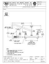
Faucet
Removal
The faucet coupler provides a means for filling and
draining the portable dishwasher. It connects to a special
adapter which in turn is connected to a faucet at a sink.
When the dishwasher is not in use, the faucet coupler is
stored in a retainer on the rear of the dishwasher cabinet.
1. Disconnect power to the machine.
2. Remove Wood Top, see "Wood Top" removal
procedure.
3. Remove Foil Bottom, see "Foil Bottom" removal
procedure.
4. Disconnect power cord from the terminal box.
Disconnect the fill hose from the water valve and the
drain hose from the drain pump.
5. Remove the wire tie securing the drain and fill hoses
to a rib on the tub.
NOTE: Repair of the faucet coupler can be done
without removing the hose assembly from the
dishwasher.
Retainer - Faucet Coupler
Removal
The retainer provides a storage area for the coupler and
power cord when dishwasher is not in use.
1. Remove Cabinet, see "Cabinet" removal procedure.
Casters
Removal
1. Disconnect power to the machine.
2. Lift or block the dishwasher up to access the casters.
3. With a screwdriver, pry the caster from the socket.

20 16026945 ©2006 Maytag Services
Disassembly Procedures
!
WARNING
To avoid risk of electrical shock, personal injury, or death, disconnect electrical power source to unit and discharge
capacitor through a 10,000 ohm resistor before attempting to service, unless test procedures require power to be
connected. Ensure all ground wires are connected before certifying unit as repaired and/or operational.
Inner Door Panel
Removal of the Inner Door Panel will allow access to the
Microprocessor Board, Door Switches, Detergent / Rinse
Aid Dispenser, and Vent Assembly.
Removal
1. Disconnect power to the machine.
2. Open the Dishwasher door.
3. Remove the 11 Torx™ screws along the sides and
top of the Inner Door Panel.
4. Separate the Inner Door Panel from the Outer Door.
5. Disconnect wires from the Vent and Dispenser Wax
Motors before pulling the Inner Door Panel away
from the Dishwasher.
Detergent / Rinse Dispenser Mechanism
and Reservoir
Checking Operation
1. Disconnect power to the machine.
2. Remove the Inner Door Panel, see "Inner Door Panel"
removal procedure.
3. Snap the Detergent Door shut.
4. Gently lift the lever of the dispenser mechanism until
a click is herd. The Detergent Door releases. Re-
lease the lever.
5. Lift the lever again. Now the actuator will lift the Rinse
Aid Plunger.
/