Fire Magic E1060S4E1N71 Owner's manual
- Category
- Barbecues & grills
- Type
- Owner's manual

1
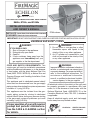
IMPORTANT: READ THESE INSTRUCTIONS CAREFULLY BEFORE STARTING INSTALLATION OR USE.
WARNING:
1. Do not store or use gasoline or other
fl ammable vapors and liquids in the
vicinity of this or any other appliance.
2. An LP cylinder not connected for use
shall not be stored in the vicinity of this
or any other appliance.
CODE AND SUPPLY REQUIREMENTS: This
outdoor gas grill must be installed in accordance
with local codes and ordinances, or, in the absence
of local codes, with the latest National Fuel Gas
Code (ANSI Z223.1/NFPA 54), or Natural Gas and
Propane Storage and Handling Installation Code
(CSA-B149.1).
This appliance and its dedicated manual shutoff
valve must be disconnected from the gas-supply
piping system when testing the system at pressures
in excess of ½ psig (3.5 kPa).
This appliance must be isolated from the gas-
supply piping system by closing its dedicated
manual shutoff valve during any pressure testing
of the gas-supply system at pressures up to and
including ½ psig (3.5 kPa).
All electrical outlets in the vicinity of the grill must
be properly grounded in accordance with local
codes, or, in the absence of local codes, with the
National Electrical Code, ANSI/NFPA 70, or the
Canadian Electrical Code, CSA C22.1, whichever
is applicable.
Keep all electrical-supply cords and fuel-supply
hoses away from any heated surface.
Certifi ed to: ANSI Z21.58b-2012
CSA 1.6b-2012
Robert H. Peterson Co. • 14724 East Proctor Avenue • City of Industry, CA 91746
INSTALLER: Leave these instructions with consumer.
CONSUMER: Retain for future reference.
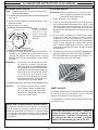
SAFETY AND WARNING CODES
DANGER:
IF YOU SMELL GAS:
1. Shut off the gas to the appliance.
2. Extinguish any open fl ame.
3. Open lid.
4. If odor continues, keep away from the
appliance and immediately call your
gas supplier or the fi re department.
Robert H. Peterson Co. • 14724 East Proctor Avenue • City of Industry, CA 91746
WARNING:
Improper installation, adjustment, alteration,
service, or maintenance can cause injury
or property damage. For proper installation,
refer to the installation instructions. For
assistance or additional information,
consult a qualifi ed professional installer,
service agency, or the gas supplier.
WARNINGS AND SAFETY CODES
10-32
OUTDOOR STAND-ALONE GAS GRILL
INSTALLATION INSTRUCTIONS
AND OWNER’S MANUAL
E660s, E790s, and E1060s
Proper operation of your grill requires
prompt and periodic maintenance.
See the CARE & CLEANING section
for details.
REV 5 - 1405281445
L-C2-330
ECHELON
diamond series
E790s shown

2
IMPORTANT: LISEZ CES INSTRUCTIONS SOIGNEUSEMENT AVANT DE COMMENCER L’INSTALLATION OU L’UTILISATION
ECHELON GRIL EXTÉRIEUR DE GAZ DU PORTATIF
DANGER:
SI VOUS SENTEZ LE GAZ :
1. Coupez l’admission de gaz de
I’appariel.
2. Éteindre toute fl amme nue.
3. Ouvrir le couvercle.
4. Si l’odeur persiste, éloignez-vous de
l’appareil et appelez immédiatement
le fournisseur de gaz ou le service
d’incendie.
AVERTISSEMENT:
1. Ne stockez pas ou n’employez pas
l’essence ou d’autres vapeurs et liquides
infl ammables à proximité de ceci ou
d’aucun autre appareil.
2. Un cylindre de propane non relié pour
l’usage ne sera pas stocké à proximité
de ceci ou d’aucun autre appareil.
CONDITIONS DE CODE ET D’APPROVISIONNEMENT:
Ce gril doit être installé selon des codes et des ordonnances
locaux, ou, en l’absence des codes locaux, avec l’un ou l’autre
le plus défunt Code national de gaz de carburant (norme ANSI
Z223.1/NFPA 54), et Stockage de gaz naturel et de propane
et manipulation du code d’installation (CSA-B149.1).
Cet appareil et ses différents robinets d’isolement doivent être
démontés du gaz-fournissent le système siffl ant en examinant
le système aux pressions au-dessus du ½ psig (kPa 3.5).
Cet appareil doit être isolé dans gaz-fournissent le système
siffl ant par fermeture que ses différents robinets d’isolement
manuels pendant tous les essais sous pression du gaz-
fournissent le système aux pressions jusques et y compris
le ½ psig (kPa 3.5).
Toutes les sorties électriques à proximité du gril doivent être
correctement fondues selon des codes locaux, ou en l’absence
de local code, avec le code électrique national, ANSI/NFPA
70, ou le code électrique canadien, CSA C22.1, celui qui est
applicable.
Maintenez tout électrique-fournissent des cordes et carburant-
fournissent des tuyaux partis de n’importe quelle surface de
chauffage.
Certifi é à la norme ANSI : Z21.58b-2012 / CSA 1.6b-2012
INSTALLATEUR : Laissez ces instructions avec le consommateur.
CONSOMMATEUR : Maintenez pour la future référence.
AVERTISSEMENT:
L’installation inexacte, l’ajustement, le
changement, le service, ou l’entretien
peuvent causer des dommages ou des
dégats matériels. Référez-vous à ce
manuel. Pour l’aide ou l’information
additionnelle, consultez un installateur
professionnel qualifi é, l’agence de service,
ou le fournisseur de gaz.
SÛRETÉ ET CODES D’AVERTISSEMENT
• Ce gril est pour ultilisation à l’extérieur seulement.
Si l’appareil est entreposé à l’intérieur, enlever les
bouteilles et les laisser à l’extérieur.
• Ne pas ranger le gril immédiatement aprés l’avoir utilisé.
le laisser refroidir avant de le déplacer ou de la ranger.
Le non respect de cette mesure de sécurité pourrait
entraîner un incendie causant des dommages à la
propriété, des blessures ou la mort.
• Ne pas utiliser cet appareil sous une surface
combustible.
• Ne pas utiliser cet appareil sous un auvent. Le non
respect de cette mesure de sécurité pourrait entraîner
un incendie ou des blessures.
• Dégagement minimal entre les parois latérales et
l’arriére de l’appareil et la construction combustible (45.7
cm à partir des parois latérales et 45.7cm à partir de
l’arriére).
• Le régulareur de pression de gaz prévu avec cet appareil
de cuisson à gaz pour l’extérieur doit être utilisé. Ce
régulateur est réglé pour une pression de sortie de 5
pouces de colonne de l’eau pour le gaz naturel, et 10
pouces pour le propane.
• LE RÉGULATEUR INCLUS D’APPAREILS EST ÉVALUÉ
POUR LE MAXIMUM DE 1/2 (LIVRES PAR POUCE
CARRÉ). SI VOTRE OFFRE DE GAZ EST 1/2 PLUS
GRAND QUE (LIVRES PAR POUCE CARRÉ), UN
RÉGULATEUR ADDITIONNEL DOIT ÊTRE INSTALLÉ
AVANT LE GRIL. VOIR LA SECTION DE CONDITIONS
D’OFFRE DE GAZ POUR LA PRESSION APPROPRIÉE
D’OFFRE DE GAZ.
• Ne couvrez jamais la surface entière de cuisine ou de
gril de gauffreuses ou de casseroles. La surchauffe se
produira et les brûleurs ne seront pas très performants
quand la chaleur de combustion est emprisonnée au-
dessous de la surface à cuire.
• Ne pulvérisez jamais l’eau sur une unité chaude de gaz,
comme ceci peut endommager des composants de
porcelaine ou de fer de fonte.
• Une fuite de GPL peut causer une incendie ou une
explosion si enflammée entraînant des blessures
corporelles graves ou la mort.
• Communiquez avec le fournisseur de GPL pour les
réparations ou pour disposer de qules bouteille ou du
GPL non utilisé.
INSTALLATION INSTRUCTIONS ET MANUEL DU PROPRIÉTAIRE
REV 5 - 1405281445
L-C2-330

3
CONTENTS
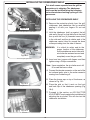
To protect against electric shock, do not immerse cord or plugs in water or other liquid;
Unplug from the outlet when not in use and before cleaning. Allow to cool before putting on or taking off
parts;
Do not operate any outdoor cooking gas appliance with a damaged cord, plug, or after the appliance
malfunctions or has been damaged in any manner. Contact the manufacturer for repair;
Do not let the cord hang over the edge of a table or touch hot surfaces;
Do not use an outdoor cooking gas appliance for purposes other than intended;
When connecting, fi rst connect plug to the outdoor cooking gas appliance then plug appliance into the outlet;
Use only a Ground Fault Circuit Interrupter (GFCI) protected receptacle with this outdoor cooking gas
appliance;
Never remove the grounding plug or use with an adapter of 2 prongs.
Use only extension cords with a 3 prong grounding plug, rated for the power of the equipment, and
approved for outdoor use with a W-A marking.
ELECTRICAL SAFETY
REV 5 - 1405281445
L-C2-330
4 REPLACEMENT COMMON PARTS LIST
6 SINGLE SIDEBURNER UNIQUE PARTS LIST
7 DOUBLE SIDEBURNER UNIQUE PARTS LIST
8 POWER BURNER UNIQUE PARTS LIST
9 ELECTRICAL CONNECTIONS
9 GRILL MAINTENANCE AND SAFETY INFORMATION
9 MASTER SWITCH
10 MODEL SPECIFICATIONS TABLE
11 STAND-ALONE GRILL DIMENSIONS TABLE
12 INSTALLATION REQUIREMENTS
13 ENSURING PROPER COMBUSTION AIR AND COOLING AIRFLOW
13 EXHAUST REMOVAL
14 LOCATION PREPARATION
14 CONNECTING THE GAS SUPPLY
14 INSTALLING THE STAND-ALONE UNIT
15 INSTALL ZONE DIVIDERS
17 SAFE USE & MAINTENANCE OF PROPANE GAS CYLINDERS
18 INSTALLING THE SIDEBURNER SHELF
19 IDENTIFICATION OF GRILL CONTROLS
20 OPTIONAL POWER HOOD
21 LIGHTING (IGNITION) INSTRUCTIONS
23 DIGITAL THERMOMETER / INTERIOR AND KNOB LIGHTS
26 ROTISSERIE INSTRUCTIONS
27 USING THE FOLDING SHELF
28 POWER BURNER
29 OPTIONAL INFRARED BURNER OPERATION
30 GRILLING TIPS
31 ACCESSORIES
32 FIRE MAGIC
®
DRIP TRAY
33 REPLACING HALOGEN BULBS
34 POWER SUPPLY FUSE REPLACEMENT
35 CARE & CLEANING
36 CONVERTING THE GAS TYPE
39 BURNER AIR SHUTTER ADJUSTMENT
42 DOUBLE SIDEBURNER
44 GRILL NOTES PAGE
45 TROUBLESHOOTING
46 WARRANTY

4
REPLACEMENT COMMON PARTS LIST
Fig. 4-1
To order replacement
parts, contact your local
Fire-Magic dealer.
Items in light gray are
not available on all
models.
E660s & E790s grills are
equipped with two drawers
on the right side of the unit.
REV 5 - 1405281445
L-C2-330
G
2
1
7
6
62
10
10
11
15
16
3
9
18
13
22
64
27
46
17
23
9
12
26
48
29
30
41
47
45
54
55
53
52
19
58
21
20
28
63
14
24
25
5
4
61

5
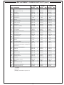
REPLACEMENT COMMON PARTS LIST (cont.)
REV 5 - 1405281445
L-C2-330
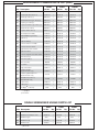
E660s E790s E1060s
Item Description Part No. Qty. Part No. Qty. Part No. Qty.
1.
Stainless cooking grid (set of 3 or 4) 3544-S-3 1 3539-S-3 1 3539-S-2 2
2.
Flavor grid (set of 3 or 4) 3057-S-3 1 3056-S-3 1 3056-S-4 1
3.
Main burner 3041-50 3 3041-50 3 3041-50 4
4.
Heatshield kit 24177-05 3 24177-05 3 24177-05 4
5.
Silicone gasket 24177-06 3 24177-06 3 24177-06 4
6.
Infrared burner * 3050 1 3050 1 3050 1
7.
Oven lid 23738-53 1 23745-53 1 23747-53 1
or
Oven lid w/ window 24193-54 1 24188-54 1 24183-54 1
8.
Window (only)*‡ 24187-45 1 24187-45 1 24187-45 1
9.
Warming rack 36735-M 1 36755-M 1 36745-M 1
10.
Back burner assembly 24794-02 1 24789-02 1 24784-02R/L 1
11.
Back burner cover 24794-010 1 24789-010 1 24784-010 2
12.
Zone separator 3061-S 2 3061-S 2 3061-S 3
13.
Heavy-duty rotisserie motor 3600-05M 1 3600-05M 1 3600-05M 1
14.
Heavy-duty rod 3606-40 1 3609-40 1 3607-40 1
15.
Heavy-duty rod knob 24187-16 1 24187-16 1 24187-16 1
16.
Meat holder (pair) 3613 1 3613 1 3613 1
17.
Counterbalance 3620E 1 3620E 1 3620E 1
18.
Grid lifter 3519 1 3519 1 3519 1
19.
Convertible regulator PR-4 1 PR-4 1 PR-4 1
20.
Control panel w/ back burner and raceway † 24394-47 1 24389-47 1 24384-47 1
or
Control panel w/ back burner, raceway, and
wire harness †
24394-49 1 24389-49 1 24384-49 1
21.
Valve manifold w/ back burner 24393-22 1 24388-22 1 24383-22 1
22.
Small knob 24182-42 2 24182-42 2 24182-42 3
23.
Large knob 24182-41 3 24182-41 3 24182-41 4
24.
LED disk (small) 24182-64 2 24182-64 2 24182-64 3
25.
LED disk (large) 24182-63 3 24182-63 3 24182-63 4
26.
Digital thermometer 24182-12 1 24182-12 1 24182-12 1
27.
Meat probe 24187-14S 1 24187-14S 1 24187-14S 1
28.
Power supply w/ outlet † 24387-18 1 24387-18 1 24387-18 1
29.
Drip tray 3087 1 3087 1 3087 1
30.
Drip tray liner (set of 4) 3557 1 3557 1 3557 1
31.
Wire harness for raceway ‡ 24194-47 1 24189-47 1 24184-47 1
32.
Back burner electrode *‡ 4199-52 1 4199-52 1 4199-52 2
* If equipped
‡ Not shown
† Add (M) to part number for power hood

6
REPLACEMENT COMMON PARTS LIST (cont.)
REV 5 - 1405281445
L-C2-330
E660s E790s E1060s
Item Description Part No. Qty. Part No. Qty. Part No. Qty.
33.
Electrode‡ 3199-72 3 3199-72 3 3199-72 4
34.
Thermometer wire harness ‡ 24187-13 1 24187-13 1 24187-13 1
35.
Natural gas orifi ce(s) ‡ 3001-42-3 1 3001-38-3 1 3001-40-4 1
36.
Natural back burner gas orifi ce(s) ‡ 3001-53-1 1 3001-51-1 1 3001-53-2 1
37.
Propane gas orifi ce(s) ‡ 3001-54-3 1 3001-53-3 1 3001-53-4 1
38.
Propane back burner gas orifi ce(s) ‡ 3001-63-1 1 3001-57-1 1 3001-63-2 1
39.
Natural smoker orifi ce ‡ 3003-68-1 1 3003-68-1 1 3003-68-1 1
40.
Propane smoker orifi ce ‡ 3003-77-1 1 3003-77-1 1 3003-77-1 1
41.
Wood chip box assembly 24182-45 1 24182-45 1 24182-45 1
42.
12v / 10 watt halogen bulb ‡ 24187-15 2 24187-15 2 24187-15 3
43.
Light lens ‡ 24187-26 2 24187-26 2 24187-26 3
44.
Lamp assembly ‡ 24187-28 2 24187-28 2 24187-28 3
45.
Power hood motor assembly * 24183-18 1 24183-18 1 24183-18 1
46.
Power hood rocker switch * 24187-39 1 24187-39 1 24187-39 1
47.
Lighted master shut-off switch 24182-46 1 24182-46 1 24182-46 1
48.
Light microswitch 24187-20 1 24187-20 1 24187-20 1
or
Power hood light & motor microswitch 24187-44 1 24187-44 1 24187-44 1
49.
Flash tube (left) ‡ 24187-29 1 24187-29 1 24187-29 1
50.
Flash tube (right) ‡ 24187-35 2 24187-35 2 24187-35 3
51.
Flex connector ‡ 3030-08 1 3030-08 1 3030-08 1
52.
Tool holder 25387-12 1 25387-12 1 25387-12 1
53.
Paper towel holder 25387-11 1 25387-11 1 25387-11 1
54.
Propane tank tray
(propane models only)
25386-21 1 25386-21 1 25386-21 1
55.
Propane regulator with hose
(propane models only)
5110-15 1 5110-15 1 5110-15 1
56.
Quick-disconnect hose ‡
(natural models only)
5110-03 1 5110-03 1 5110-03 1
57.
Power cord ‡ 25387-13 1 25387-13 1 25387-13 1
58.
Folding shelf 24336-15 1 24336-15 1 24336-15 1
59.
Fire Magic
®
cookbook ‡ 3595 1 3595 1 3595 1
* If equipped
‡ Not shown
E660s E790s E1060s
Item Description Part No. Qty. Part No. Qty. Part No. Qty.
60.
Sideburner (burner only) ‡ 3279-32 1 3279-32 1 3279-32 1
61.
Sideburner assembly w/ shelf 24336-16 1 24336-16 1 24336-16 1
62.
Sideburner grid 3552 1 3552 1 3552 1
63.
Sideburner cap 3275-36 1 3275-36 1 3275-36 1
64.
Sideburner lid 24336-31 1 24336-31 1 24336-31 1
‡ Not shown
SINGLE SIDEBURNER UNIQUE PARTS LIST

7
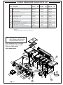
DOUBLE SIDEBURNER UNIQUE PARTS LIST
Fig. 7-1
Note: See page 4-6 for common part
and number identification.
Some quantities may vary.
Grills equipped with a double
sideburner are available for 660s,
790s, and 1060s series.
1060s shown here.
REV 5 - 1405281445
L-C2-330
G
7
27
46
9
26
48
29
30
41
45
54
53
52
58
28
62
60
66
29
64
63
19
21
55
54
65
24
25
22
23
47
20
E660s E790s E1060s
Item Description Part No. Qty. Part No. Qty. Part No. Qty.
20.
Main control panel w/ raceway † 34394-13 1 34389-13 1 34384-13 1
or
Main control panel w/ raceway and wire harness † 34394-18 1 34389-18 1 34384-18 1
21.
Main valve manifold 24193-22 1 24188-22 1 24383-28 1
60.
Double sideburner valve manifold 3281-22 1 3281-22 1 3281-22 1
61.
Double sideburner (only) ‡ 3279-32 2 3279-32 2 3279-32 2
62.
Double sideburner grid 3529-S 1 3529-S 1 3529-S 1
63.
Sideburner cap 3275-36 2 3275-36 2 3275-36 2
64.
Double sideburner cover 3281-07 1 3281-07 1 3281-07 1
65.
Convertible regulator
(for double sideburner valve manifold)
PR-4 1 PR-4 1 PR-4 1
66.
Double sideburner control panel N/A N/A 23281-12 1
67.
Double sideburner wire harness extension ‡ 34394-19 1 34394-19 1 34394-19 1
* If equipped
‡ Not shown
† Add (M) to part number for power hood control panel

8
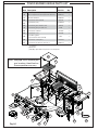
POWER BURNER UNIQUE PARTS LIST
Fig. 8-1
Note: See page 4-6 for common part
and number identification.
Some quantities may vary.
REV 5 - 1405281445
L-C2-330
G
7
62
58
27
47
9
26
48
29
30
41
46
45
54
53
52
58
28
21
66
29
29
54
64
55
61
63
19
60
65
24
25
22
23
20
E1060s
Item Description Part No. Qty.
20.
Main control panel w/ raceway † 34384-14 1
or
Main control panel w/ raceway and wire harness † 34384-18 1
21.
Main valve manifold 24383-28 1
60.
Power burner valve manifold 3278-14 1
61.
Power burner (only) 3278-01B 1
62.
Power burner grid - stainless steel 3545-S 1
or
Power burner grid - porcelain cast 3545 1
63.
Power burner collimator 3279-09 1
64.
Power burner cover 3278-06 1
65.
Convertible regulator
(for power burner valve manifold)
PR-4 1
66.
Power burner control panel 23278-10 1
67.
Power burner wire harness extension ‡ 34384-19 1
* If equipped
‡ Not shown
† Add (M) to part number for power hood control panel

9
ELECTRICAL CONNECTIONS
This grill requires 120VAC power to opperate.
Plug the power supply cord into a properly wired
and inspected GFCI electrical receptacle (15 AMP
minimum). Use a heavy-duty grounded extension
cord if necessary.
WARNING
Electrical Grounding Instructions
For your protection against shock hazard, this
outdoor-cooking gas-appliance is equipped with
a three-pronged (grounding) electrical connector.
This appliance should be connected to a properly
grounded three-prong receptacle using a grounding
extension cord rated for outdoor use. Do not cut or
remove the grounding prong from the connector.
Important: ONLY REPLACE THE OVEN LIGHTS
WITH 12V / 10 WATT HALOGEN BULB(S).
1. The outdoor grill and surrounding area MUST
remain clear of fl ammable substances such as
gasoline, yard debris, wood, etc.
2. The airfl ow through the vent space located below
the control panel must remain unobstructed.
3. When using propane gas:
a. The required ventilation openings in the
enclosure must be clear of debris.
b. The propane cylinder, regulator, and rubber
hose must be in a location not subject to
temperature above 125° F (51° C).
4. The fl ames on each burner burn evenly along
the entire burner with a steady fl ame (mostly
blue). If burner fl ames are not normal, check
and clean the orifi ce and burner/venturi tubes
for insects and insect nests. A clogged tube can
lead to a fi re beneath the grill. A proper fl ame
pattern will ensure safe operation and optimal
performance. Adjust the air shutter as needed
(see AIR SHUTTER ADJUSTMENT).
5. The in-line gas valve or gas cylinder valve must
always be shut OFF when the grill is not in use.
6. The drip collector holes must be clear and
unobstructed. Excessive grease deposits can
result in a grease fi re.
7. The back burner, sideburner, or IR burner cover
must be removed before using the burner.
8. Whenever reconnecting any wires, apply a
small amount of dielectric grease to the male
connector, then make the connection.
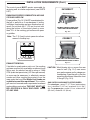
GRILL MAINTENANCE AND SAFETY INFORMATION
WARNING: NEVER cover the entire cooking or grill surface with griddles or pans. Overheating will occur, and
burners will not perform properly when combustion heat is trapped below the cooking surface.
CAUTION: NEVER spray water on a hot gas unit.
Important: When reviewing this units wiring connections; please refer to the wiring diagram
label affi xed to the inside of the control panel.
The grill serial identifi cation number is located on the underside of the drip tray handle. It
is recommended that the drip tray fi rst be removed and cleaned / emptied of its contents,
then turned over to view.
REV 5 - 1405281445
L-C2-330
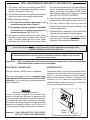
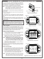
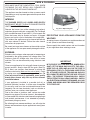
MASTER SWITCH
The master switch is push button operated, and is
located on the right side of the control panel (see
Fig. 9-1). It controls the power to all lights, igniters,
and the thermometer. It allows the power to be
turned on or off for safety and convenience. The
switch will need to be turned on prior to each grill
use, and turned off after each use.
Master
switch
Fig. 9-1

10
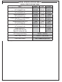
MODEL SPECIFICATIONS TABLE
MODEL SPECIFICATIONS TABLE
Table 1 E660s E790s E1060s
Main burner BTU (per burner)
N/P orifi ce drill size
25,000
x
3
#42/#54
32,000
x
3
#38/#53
28,000
x
4
#40/#53
Back burner BTU (per burner)
N/P orifi ce drill size
11,000
#53/#63
13,000
#51/#57
11,000
x
2
#53/#63
Single sideburner BTU*
N/P orifi ce drill size
15,000
#50/#58
15,000
#50/#58
15,000
#50/#58
Double sideburner BTU (per burner)*
N/P orifi ce drill size
15,000
x
2
#50/#58
15,000
x
2
#50/#58
15,000
x
2
#50/#58
Smoker drawer burner BTU
N/P orifi ce drill size
3,000
#68/#77
3,000
#68/#77
3,000
#68/#77
Infrared searing burner BTU (per burner)*
N/P orifi ce drill size
24,000
#45/#55
24,000
#45/#55
24,000
#45/#55
Power burner BTU*
Left N/P orifi ce drill size
Right N/P orifi ce drill size
- -
60,000
#30/#50
#46/#1.25
GFCI Receptacle Rating 120VAC / 10A Max
Power Supply Rating 120VAC / 1.5A / 60 Hz
Oven Lights Rating 12V / 10 watt halogen bulb
*
If equipped
REV 5 - 1405281445
L-C2-330

11
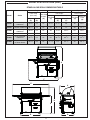
MODEL SPECIFICATIONS (cont.)
H
C
G
E
B
D
A
F
STAND-ALONE GRILL DIMENSIONS TABLE
Model Series
Height Width Depth
Floor to top
(with oven)
Floor to top
of shelf
(C)
Left to right Front to back
Cart base
(D)
(with shelves)
Cart base
(G)
Maximum
outer
(H)
Open
(A)
Closed
(B)
Up
(E)
1 Up / 1 Down
(F)
E660s
w/ or w/o sIngle
sideburner
60
5
/8" 52" 37" 34
1
/4" 67
1
/2" 56" 26" 29
3
/4"
E660s
w/ double sideburner 60
5
/8" 52" 37" 53" 86
1
/4" 77" 26" 29
3
/4"
E790s
w/ or w/o sIngle
sideburner
60
5
/8" 52" 37" 40" 73
1
/4" 59
3
/4" 26 " 29
3
/4"
E790s
w/ double sideburner 60
5
/8" 52" 37" 58
3
/4" 92" 80
3
/4" 26" 29
3
/4"
E1060s
w/ or w/o sIngle
sideburner
60
5
/8" 52" 37" 53" 86
1
/4" 66
3
/4" 26 " 29
3
/4"
E1060s
w/ double sideburner
or Power burner
60
5
/8" 52" 37" 77
3
/4" 111" 93
3
/4" 26" 29
3
/4"
REV 5 - 1405281445
L-C2-330

12
INSTALLATION REQUIREMENTS
This grill is designed for outdoor use only. DO NOT use this grill
inside a building, garage, enclosed area, or under an unprotected
overhead combustible construction. See the EXHAUST REMOVAL
section on the following page for details on installing under a patio
roof. DO NOT use this grill in or on a recreational vehicle or boat.
Important: The grill is not insulated. Refer to the information
below to ensure all required clearances are met.
The grill must have a minimum clearance of 18" from
combustible materials/items AT ALL TIMES.
For the minimum clearances between the grill and any side or rear
walls, your setup must fall within one (or more) of the following:
A. Clearance between grill and combustible wall
• The grill must have a minimum of 18" right, left, and rear
clearance from any combustible wall (see Fig. 12-1).
B. Clearance between grill and strictly non-combustible wall
(i.e. brick wall, see Fig. 12-2)
• The grill must have a minimum of 4" right, left, and rear
clearance from any non-combustible wall.
(To allow for proper ventilation and prevent dangerous
overheating.)
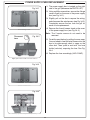
Fig. 12-1 Clearance 'A' Diagram
Combustible
Min.
18"
(Clearance required for
right, left, and rear)
Fig. 12-2 Clearance 'B' Diagram
Non-combustible
Min.
4"
(Clearance required for
right, left, and rear)
REV 5 - 1405281445
L-C2-330

13
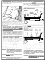
INSTALLATION REQUIREMENTS (Cont.)
The control panel MUST remain removable for
servicing and air shutter adjustment (see PARTS
LIST).
ENSURING PROPER COMBUSTION AIR AND
COOLING AIRFLOW
Proper airfl ow (Fig. 13-1) MUST be maintained for
the grill to perform as it was designed. If airfl ow
is blocked, overheating and poor combustion will
result. Do not block the 1" (2.5 cm) front air inlet
along the bottom of the control panel or more
than 75% of the cooking grid surface with pans
or griddles.
Note: The 1" (2.5 cm) front air space also allows
access to the drip tray.
EXHAUST REMOVAL
If installed or used under a patio roof, the cooking
grid area must be fully covered by an exhaust hood
with a vent. An exhaust fan with a rating of 1,000
CFM (cubic feet per minute) (472 liters per second)
or more may be necessary to effectively remove
smoke and other cooking by-products from the
area under the hood. Fire Magic Vent Hoods are
available to meet this requirement. This outdoor
grill must not be used under unprotected overhead
combustible construction. THIS UNIT MUST NOT
BE LOCATED IN A FULLY ENCLOSED AREA
OF ANY KIND.
Fig. 13-1 - Ventilation
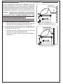
CAUTION: Wind blowing into or across the rear
oven lid vent (Fig. 13-2) can cause
poor performance and/or dangerous
overheating. Orient the grill so that the
prevailing wind blows toward the front
of the grill (Fig. 13-3).
GAS SUPPLY AND MANIFOLD PRESSURES:
For natural gas - normal 7" (17.78 cm) water column
(w.c.), minimum 5" (12.7 cm), maximum 10
1
/
2
" (26.7
cm). For propane gas - normal 11" w.c., minimum 10"
(25.4 cm), maximum 13" (33 cm).
Fig. 13-3
CORRECT
PLACE GRILL SO PREVAILING WIND
BLOWS TOWARD FRONT OF GRILL
YOU MUST PROTECT REAR OVEN
VENT FROM PREVAILING WIND
Rear oven lid vent
INCORRECT
Fig. 13-2
REV 5 - 1405281445
L-C2-330

14
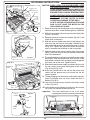
INSTALL THE TOOL HOLDER AND
PAPERTOWEL HOLDER
The rectangular mounting bracket for the tool
holder and the paper towel holder come pre-
attached to the sides of the cart.
Unpack the holder portion, squeeze the open
ends together slightly, and install them into the
mounting bracket (see Fig. 14-2). Next, release
the hanger so that the ends extend out through
the holes in the top and bottom of the mounting
bracket (Fig. 14-3, 14-4).
When not in use, the racks may be folded back
against the wall of the grill (Fig. 14-3, 14-4).
LOCATION PREPARATION
Prepare a fl at, level surface capable of supporting
the weight of the stand-alone grill and convenient to
the gas supply if connecting to a gas line.
WHEELS AND CASTERS
To lock a caster press down on the side of the lever
with the word "OFF" stamped on it until it stops and
the caster will not turn. To unlock, press down on the
side stamped "ON."
INSTALLING THE STAND-ALONE UNIT
Fig. 14-1
Caster in locked position
Fig. 14-2
Fig. 14-4
Fig. 14-3
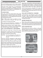
CONNECTING THE GAS SUPPLY
For connecting a propane unit to a portable
propane tank, read the safety warnings and
follow the instructions in the section SAFE USE
AND MAINTENANCE OF PROPANE GAS
CYLINDERS.
For household propane or natural gas units:
a. Turn OFF the gas supply at the source. The
quick disconnect hose is pre-installed on the
valve manifold at the manufacturer. Run the
hose through the hole in the bottom rear of the
stand-alone unit, to the gas supply. Connect
the
1
/
2
" NPT socket at the end of the hose to
the gas supply. Use pipe joint compound that is
resistant to all gasses on the male pipe fi tting
and tighten securely. DO NOT use pipe joint
compound to connect the fl are fi ttings.
c. Turn all burner valves to the OFF position. Turn
the gas supply on. Then carefully check all gas
connections for leaks with a brush and soapy
water before lighting. NEVER USE A MATCH
OR OPEN FLAME TO TEST FOR LEAKS.
REV 5 - 1405281445
L-C2-330

15
Fig. 15-1
Zone divider
Groove
Groove
Front
INSTALL ZONE DIVIDERS
REV 5 - 1405281445
L-C2-330
INSTALL ZONE DIVIDERS
Place the zone dividers as shown (Fig. 15-1)
into the grooves in the inner fi rewall of the grill to
allow for maximum heat control and thermometer
accuracy in each zone. Remove and store during
rotisserie use.

16
U
L
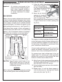
Fig. 16-1 type coupleur rapide de fi l de point culminant d’I
Valve
de
décompression
QCC
Type 1
Valve
Ajustage de précision
en laiton de fi l de
point culminant
Indicateur
de niveau
de liquide
(facultatif)
Écrou de main avec le
fi l de point culminant.
Régulateur
Passage
Tuyau
Volant de commande
main dans le sens des aiguilles d’une montre pour engager les
fi ls et pour serrer jusqu’à ce que douillettement. L’utilisation des
pinces ou de la clé ne devrait pas être nécessaire. Seulement
le propane marqué par cylindres doit être employé.
Pour débrancher: Tournez l’écrou de main dans le sens
contraire des aiguilles d’une montre jusqu’à isolé (fi g. 16-1).
Important: Avant d’employer le gril, et ensuite chaque
fois que le cylindre est enlevé et rattaché,
examinez tous les raccordements pour déceler
les fuites. Arrêtez les valves de gril et ouvrez
la valve principale de cylindre, puis vérifi ez
les raccordements avec de l’eau savonneux.
Réparez toutes les fuites avant d’allumer le gril.
ATTENTION: Tournez toujours la valve principale de cylindre
de propane au loin après chaque utilisation,
et avant de déplacer le gril et le cylindre, ou
débrancher l’accouplement. Cette valve doit
rester fermée et le cylindre a débranché alors
que l’appareil n’est pas en service, quoique
l’écoulement de gaz soit arrêté par un dispositif
de sûreté quand le coupleur est débranché.
Inspectez soigneusement l’ensemble de tuyau chaque fois
avant que le gaz soit allumé. Un tuyau fi ssuré ou effi loché doit
être immédiatement remplacé.
Si l'appareil est stocké à l'intérieur, le cylindre doit être disconnected
et a enlevé. Des cylindres Disconnected doivent être stockés
dehors, hors de la portée des enfants, avec les prises de valve
fi letées étroitement installées, et ne doivent pas être stockés dans
un bâtiment, le garage, ou n'importe quel autre secteur inclus.
POUR VOTRE SÛRETÉ
a. Ne stockez pas un cylindre de gaz disponible de propane
dessous ou ne vous approchez pas de cet appareil.
b. Ne remplissez jamais cylindre au delà de 80 pour cent de
plein.
c. SI L’INFORMATION DANS “A” ET “B” N’EST PAS SUIVIE
EXACTEMENT, UN FEU CAUSANT LA MORT OU DES
DOMMAGES SÉRIEUX PEUT SE PRODUIRE.
IMPORTANT POUR VOTRE SÛRETÉ
LISEZ ET SUIVEZ TOUS LES AVERTISSEMENTS ÉQUIPÉS DE VOTRE CYLINDRE DE GAZ DE PROPANE.
En actionnant cet appareil avec un cylindre de gaz de propane ON DOIT observer ces instructions et avertissements.
LE MANQUE DE FAIRE AINSI PEUT AVOIR COMME CONSÉQUENCE UNE INCENDIE OU UNE EXPLOSION SÉRIEUSE.
CYLINDRE ET CONDITIONS ET
CARACTÉRISTIQUES DE CONNECTEUR
a. Des cylindres et les valves de gaz de propane doivent être
maintenus en bon état et doivent être remplacés s’il y a
des dommages évidents au cylindre ou à la valve.
b. Ce gril, une fois utilisé avec un cylindre, devrait être relié à
un gallon de la norme 5 (20lb.) cylindre de gaz de propane
équipé d’un OPD (remplissez au-dessus du niveau le
dispositif d’empêchement). L’OPD a été exigé sur tous les
cylindres vendus depuis octobre 1.1998 pour empêcher le
remplissage excessif.
c. Les dimensions de cylindre devraient être approximativement
12"(30.5cm) de diamètre et 18" (45.7cm) hauts. Des
cylindres doivent être construits et marqués selon les
caractéristiques pour des cylindres de gaz de propane du
département des ETATS-UNIS du transport (D.O.T.) ou
le niveau national du Canada, du CAN/CSA-B339, des
cylindres, des sphères et des tubes pour le transport des
marchandises dangereuses.
d. Le cylindre doit inclure un collier pour protéger la valve
de cylindre et le circuit d’alimentation de cylindre doit être
assuré le retrait de vapeur.
e. Le montage du régulateur de pression et le fl exible (Fig. 16-1)
fourni avec cet appareil au gaz en plein air (modèles au
propane seulement) doit être utilisé. Assemblées d'origine et
régulateur de pression et le tuyau de remplacement doivent
être ceux spécifi és par le fabricant pour le raccordement d'un
dispositif de cylindre de liaison identifi ée comme de type I par
le 21.58-2005/CGA ANSI Z 1.6 à 2005 (voir liste des pièces
pour les informations de commande).
f. La valve de cylindre de gaz de propane doit être équipée
d’un dispositif d’accouplement de raccordement de
cylindre, décrit comme type I dans la norme défi nie dans le
e. de paragraphe ci-dessus. Ce dispositif est généralement
décrit comme coupleur rapide de fi l de point culminant.
g. Si votre cylindre de gaz de propane vient avec une prise
de la poussière, placez le bouchon anti-poussière sur la
sortie de valve de cylindre toutes les fois que le cylindre
n’est pas en service.
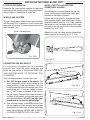
OPÉRATION DE COUPLEUR RAPIDE
Pour relier le regulator/hose à l’ajustage de précision de
valve de cylindre de gaz de propane: Serrez l’écrou de main
sur le régulateur au-dessus de l’ajustage de précision de fi l
de point culminant sur la valve de cylindre. Tournez l’écrou de
1
2
3
4
FIXATION DU CYLINDRE DE GAZ DE PROPANE
1. Soulevez la poignée de
verrouillage pour ouvrir
le plateau et pour tirer à
l’extérieur.
3. Avec le cylindre de gaz en place et relié,
glissez le plateau de nouveau dans la poignée
de verrouillage de chariot et de serrure en
poussant fermement en bas.
2. Placez le cylindre de gaz de propane gainent fermement sur
le plateau avec la base insérée dans le trou central et le collier
s’ouvrant au dos. Suivez les instructions de relier ci-dessus
l’approvisionnement.
Fig. 16-2
Fig. 16-3
Fig. 16-5
Fig. 16-4
Ouverture
de Collier
UTILISATION SÛRE ET ENTRETIEN DES CYLINDRES DE GAZ DE PROPANE

17
U
L
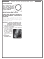
Fig. 17-1 Type I Acme thread quick coupler
Pressure
relief
valve
QCC
Type 1
valve
Brass Acme
thread fi tting
Liquid level
indicator
(optional)
Hand nut with Acme
thread
Regulator
Vent
Hose
Hand wheel
The use of pliers or a wrench should not be necessary. Only
cylinders marked “propane” may be used.
To disconnect: Turn the hand nut counterclockwise until
detached (Fig. 17-1).
Important: Before using the unit, and after each time the
cylinder is removed and reattached, check
the hose for wear (see a.) and check all
connections for leaks. Turn off the unit valves
and open the main cylinder valve, then check
connections with soapy water. Repair any
leaks before lighting the unit.
CAUTION: Always turn the propane cylinder main valve
off after each use, and before moving the unit
and cylinder or disconnecting the coupling.
This valve must remain closed and the
cylinder disconnected while the appliance
is not in use, even though the gas fl ow is
stopped by a safety feature when the coupler
is disconnected.
Carefully inspect the hose assembly each time before the
gas is turned on. A cracked or frayed hose must be replaced
immediately.
If the appliance is stored indoors, the cylinder must be
disconnected and removed. Disconnected
cylinders must be
stored outdoors, out of the reach of children, with threaded
valve plugs tightly installed, and must not be stored in a
building, garage, or any other enclosed area.
FOR YOUR SAFETY
a. DO NOT store a spare propane-gas cylinder under or
near this appliance.
b. NEVER fi ll the cylinder beyond 80-percent full.
c. IF THE INFORMATION IN a. AND b. IS NOT FOLLOWED
EXACTLY, A FIRE CAUSING DEATH OR SERIOUS
INJURY MAY OCCUR.
IMPORTANT FOR YOUR SAFETY
READ AND FOLLOW ALL WARNINGS PROVIDED WITH THE PROPANE-GAS CYLINDER.
When operating this appliance with a propane-gas cylinder, these instructions and warnings MUST be observed.
FAILURE TO DO SO MAY RESULT IN A SERIOUS FIRE OR EXPLOSION.
CYLINDER/CONNECTOR REQUIREMENTS
a. Propane-gas cylinders, valves, and hoses must be
maintained in good condition and must be replaced if
there is visible damage to either the cylinder or valve. If the
hose is cut or shows excessive abrasion or wear, it must
be replaced before using the gas appliance (see e.).
b. This unit, when used with a cylinder, should be connected
to a standard 5-gallon (20 lb.) propane-gas cylinder
equipped with an OPD (Overfi ll Prevention Device).
The OPD has been required on all cylinders sold since
October 1,1998, to prevent overfi lling.
c. Cylinder dimensions should be approximately 12" (30.5
cm) in diameter and 18" (45.7 cm) high. Cylinders must
be constructed and marked in accordance with the
Specifi cations for Propane Gas Cylinders of the U.S.
Department of Transportation (D.O.T.) or the National
Standard of Canada, CAN/CSA-B339, Cylinders,
Spheres, and Tubes for Transportation of Dangerous
Goods.
d. The cylinder used must include a collar to protect the
cylinder valve, and the cylinder supply system must be
arranged for vapor withdrawal.
e. The pressure regulator and hose assembly (Fig. 17-1)
supplied with this outdoor gas appliance (L.P. models
only) must be used. Original and replacement pressure
regulator and hose assemblies must be those specifi ed
by the manufacturer for connection with a cylinder
connecting device identifi ed as Type I by the ANSI Z
21.58-2005/CGA 1.6-2005 (see PARTS LIST for ordering
information).
f. The propane-gas cylinder valve must be equipped with a
cylinder connection coupling device, described as Type I
in the standard defi ned in paragraph e. above. This device
is commonly described as an Acme thread quick coupler.
g. If the propane-gas cylinder comes with a dust plug, place
the dust cap on the cylinder valve outlet whenever the
cylinder is not in use.
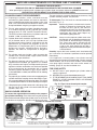
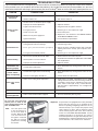
QUICK COUPLER OPERATION
To connect the regulator/hose assembly to the propane-
gas cylinder valve fi tting: Press the hand nut on the regulator
over the Acme thread fi tting on the cylinder valve. Turn the hand
nut clockwise to engage the threads and tighten until snug.
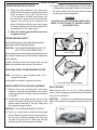
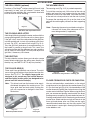
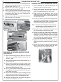
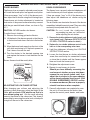
SECURING THE PROPANE-GAS CYLINDER
1. Lift latch handle to unlock
tray and pull outward.
3. With gas cylinder in place and connected, slide
tray back into cart and lock latch handle by
pushing fi rmly downward.
2. Set propane-gas cylinder into the sleeve of the extended tray with
base inserted into center hole and collar opening to back. Follow
instructions above to connect supply.
Collar
Opening
Fig. 17-2
Fig. 17-3
Fig. 17-5
Fig. 17-4
SAFE USE & MAINTENANCE OF PROPANE GAS CYLINDERS

18
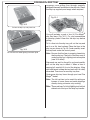
This shelf comes separate from the grill for
convenience in shipping. The sideburner
shelf must be installed using the following
instructions before hooking up the grill to a
gas source.
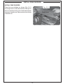
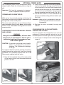
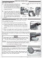
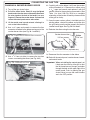
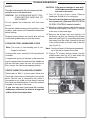
INSTALLING THE SIDEBURNER SHELF
1. Remove the protective plastic from the grill,
sideburner, and sideburner lids by carefully
peeling it off with your fingers. Do not use
tools.
2. Hold the sideburner shelf up against the left
side wall of the grill so that the holes in the shelf
line up with the four (4) threaded screw holes
in the side wall and the air-shutter end of the
sideburner venturi tube fi ts around the brass
orifi ce protruding from the side of the cart.
WARNING: It is critical for safety and for the
proper function of the sideburner
that the sideburner venturi tube with
air shutter be centered around and
completely cover the gas orifi ce.
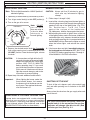
3. Insert and start screws with fi ngers and then
tighten using a Phillips screwdriver.
Note: Upon completion, the air shutter must still
fi t around the brass orifi ce.
4. Connect the female connector on the end of the
hot surface ignitor wire to the male connector
coming from inside the grill.
5. Place the burner cap on top of the burner, as
shown in Fig. 18-3.
6. Place the grid so that it rests on the front
and back lips of the sideburner opening (Fig.
18-4).
7. Proceed to the section on AIR SHUTTER
ADJUSTMENT and complete the installation by
adjusting the air shutter. This will also test the
sideburner installation.
Air-shutter orifi ce placement - under shelf
Fig. 18-1
Connecting the ignitor wires
Placing the burner cap
Fig. 18-2
Fig. 18-3
Final look
Fig. 18-4
Screw
Hole
Male
Female
Brass
orifi ce
Air
shutter
Grate
Lid
Cap
Shelf
INSTALLING THE SIDEBURNER SHELF

19
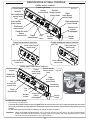
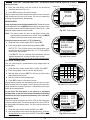
IDENTIFICATION OF GRILL CONTROLS
Power burner control locations
Double sideburner control locations
Inner power burner
control knob
Outer power burner
control knob
Fig. 19-2
Left
main burner
control knob
Right
main burner
control knob
Right backburner
control knob
Digital
thermometer
Sideburner
control knob
Center
main burner
control knob
Fig. 19-4
Left
main burner
control knob
Right
main burner
control knob
Backburner
control knob
Digital
thermometer
Sideburner
control knob
E1060s control locations
E660s and E790s control locations
Smoker
drawer burner
control knob
Center right main
burner
control knob
Center left main
burner
control knob
Drip
tray
Drip
trays
Smoker drawer
burner control
knob
Left backburner
control knob
Power hood
control
(if equipped)
Fig. 19-1
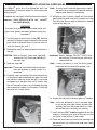
To remove the control panel:
• Turn off the gas shutoff valve.
• Pull off the control knobs. Slowly lift away the lighted bezels to clear the valve stems, and carefully disconnect the wires found
on the back of the bezels (use your fi ngernail.) Remove the smoker drawer. Unscrew and remove the control panel screws and
washers.
• Lift the control panel up and outward, allowing it to rest on the internal chain(s).
Important: When re-installing the control panel, set it back over the front lip of the grill so that the lid-closed-sensor
plunger protrudes through the hole on the upper right of the control panel. Prior to opening the gas shutoff
valve, be sure the control knobs are in the OFF position.
Control panel
screw(s)
Control panel
screw(s)
Smoker
drawer
Smoker
drawer
Fig. 19-5
Bezel
installed
Bezel
removed
Carefully
disconnect
Power hood
control
(if equipped)
Master
switch
Master
switch
Rear sideburner
control knob
Front sideburner
control knob
Fig. 19-3

20
2. Use a Phillips screwdriver to remove the stainless-
steel motor assembly housing screw. Pull the top
of the housing fi rst up and then outward away
from the lid until the top of the shroud clears the
lip of the motor mount beneath, then remove the
housing completely and set it aside (Fig. 20-3).
3. Use the Allen wrench to loosen and remove the
lid motor assembly locking bolt and washer (see
Fig. 20-4).
Important: Keep this bolt and washer for later use
in converting the unit back to automatic
lid operation.
4. Replace the motor assembly housing and
refasten.
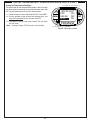
CONFIGURING THE LID FOR MOTORIZED
OPENING AND CLOSING
The unit is shipped in this confi guration, but if you have
confi gured it for manual operation and wish to use the
motorized open/close function again, follow this procedure:
1. Follow steps 1-4 except screw in the locking bolt
in step 3.
The Fire Magic
®
Power Hood is available as a factory
shipped option. Read the following before using the
grill.
Important: Grill must be connected to electrical
power to open and close lid by motor.
OPENING AND CLOSING THE LID
While set up for motorized opening and closing, the
lid may be controlled using the black rocker switch on
the right side of the control panel.
The rocker switch will lock in any one of three positions:
up–commanding the lid to open, down –commanding
the lid to close, and center–allowing the lid to hold its
current position.
CONFIGURING THE LID FOR MANUAL OPENING
AND CLOSING
WARNING
If the grill has been on recently, all Power Hood
components are potentially hot. Wait for grill to
cool before beginning this procedure or wear
heat-resistant gloves.
CAUTION: Do not push or pull on the lid or its handle
while it is configured for automatic
operation. This could result in damage
to the grill.
To confi gure the lid for manual opening and closing,
simply remove the locking bolt using the following
procedure. This procedure requires the use of the
Allen wrench supplied with this option.
1. Open the lid completely, then set the rocker switch
to the center position and disconnect electrical
power to the unit.
Fig. 20-1
Fig. 20-2
UP
DOWN
Fig. 20-3
Gear cover plate
PULL
Motor
assembly
housing
Fig. 20-4
Locking bolt
Hinge bolt
UP
DOWN
Fig. 20-1
Fig. 20-2
OPTIONAL POWER HOOD
Page is loading ...
Page is loading ...
Page is loading ...
Page is loading ...
Page is loading ...
Page is loading ...
Page is loading ...
Page is loading ...
Page is loading ...
Page is loading ...
Page is loading ...
Page is loading ...
Page is loading ...
Page is loading ...
Page is loading ...
Page is loading ...
Page is loading ...
Page is loading ...
Page is loading ...
Page is loading ...
Page is loading ...
Page is loading ...
Page is loading ...
Page is loading ...
Page is loading ...
Page is loading ...
-
 1
1
-
 2
2
-
 3
3
-
 4
4
-
 5
5
-
 6
6
-
 7
7
-
 8
8
-
 9
9
-
 10
10
-
 11
11
-
 12
12
-
 13
13
-
 14
14
-
 15
15
-
 16
16
-
 17
17
-
 18
18
-
 19
19
-
 20
20
-
 21
21
-
 22
22
-
 23
23
-
 24
24
-
 25
25
-
 26
26
-
 27
27
-
 28
28
-
 29
29
-
 30
30
-
 31
31
-
 32
32
-
 33
33
-
 34
34
-
 35
35
-
 36
36
-
 37
37
-
 38
38
-
 39
39
-
 40
40
-
 41
41
-
 42
42
-
 43
43
-
 44
44
-
 45
45
-
 46
46


Fire Magic E1060S4E1N71 Owner's manual
- Category
- Barbecues & grills
- Type
- Owner's manual
Ask a question and I''ll find the answer in the document
Finding information in a document is now easier with AI
Related papers
-
Fire Magic E1060S4EAP71 Installation guide
-
-
-
-
-
-
-
-
-
Other documents
-
AOG 3282 Series Installation guide
-
Hestan AGAD42-BU Installation guide
-
Brinkmann 4905 User manual
-
 Craftex B2982 Owner's manual
-
NAPOLEON P600 User manual
-
Traceable 3358 Owner's manual
-
Sub-Zero 826747 Installation guide
-
-
River of Goods 14006 Operating instructions
-
Electrolux 51" Stainless Steel Gas Grill User manual
