
MODEL DH 15DV
−#
1
−
1. REPAIR GUIDE:
Without fail, remove the EB 12 Battery from the main body before starting maintenance work. Because
the tool is cordless, if the battery is left in and the switch is activated inadvertently, the motor will start
rotation unexpectedly, resulting in serious hazard:
1-1. Precaution and Suggestions for Disassembly and Reassembly of the Main Body:
The circled number in the descriptions below cor-
respond to the item numbers in the Parts List and
exploded assembly diagrams.
1-1-1. Disassembly
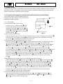
(1) Disassembly of the Chuck Section:
As shown in Fig. 1, slide the Grip
2
in the
direction indicated by the arrow mark, and
remove the Front Cap
1
. The Grip
2
, Ball
Holder
3
inside the Grip, Holder Spring
4
,
and two Steel Balls
9
can then be removed
from the Cylinder
11
.
(2) Disassembly of the Housing:
After removing the chuck section, loosen and remove the nine D4 x 20 Tapping Screws (Black)
28
and the two D4 x 14 Tapping Screws
27
which fix the main body. Then, separate the Housing
(A) (B) Set
26
by removing Housing (B) from Housing (A).
(3) Disassembly of the Hammering Mechanism Section:
When the Cylinder
11
and the Piton
21
are removed from Housing (A) in a single body, the arm
of the Reciprocation Bearing
35
will be extracted from the Piston
21
. Then extract Piston
21
from the Cylinder
11
, and with a screwdriver or slender rod push the Second Hammer
16
out
through the hole in the tip end of the Cylinder
11
to disconnect the Striker
19
retained by
O-Ring (A)
18
. Pull out the First Gear
37
without the bearing from the Second pinion
31
.
Then remove the Collar
36
and the Reciprocating Bearing
35
. Next, remove the Clutch
33
toward
the pinion side at the top of the Second Pinion
31
, and remove the O-Ring
34
. The Clutch
33
and Clutch Spring
32
can then be removed from the Second Pinion
31
. remove the Retaining
Ring for D14 Shaft
44
which fixes the Change Lever
40
on the inner side of Housing (A), and
extract the Change Lever
40
from Housing (A). Be very careful not to lose the D3.97 Steel
Ball
42
.
(4) Disassembly of the Cylinder and Second Gear (Slip Mechanism Section):
Extract the Retaining Ring
5
from the Cylinder
11
. Pull the Oil Seal
6
off of the Cylinder
11
.
Extract the Retaining Ring for D20 Shaft
7
, and remove the 6904CM Ball Bearing
8
from the
Cylinder
11
with a bearing puller. Be very careful not to lose the four D5.556 Steel Balls
10
.
Gear
12
, Spring (A)
13
, and Washer (A)
14
can then be removed from the Cylinder
11
. Ex-
tract O-Ring (D)
18
from deep within the Cylinder
11
, and remove the Second Hammer
16
from the Cylinder
11
. [O-Ring (D) can be easily removed by using a Bozan Electric Tool H-75
Spring Hook to pull it out from the outside.] To prevent idle hammering, be sure to replace
O-Ring (D)
18
whenever the unit is disassembled.
(5) Disassembly of the Motor, Switch and Terminals:
After Housing (B) has been removed, the Motor Ass’y
25
, Switch
45
, and Terminals
50
and
52
can be taken out. To disassemble the removed Motor Ass’y
25
, Switch
45
, and Terminals
50
and
52
, carefully read the following step.
1
Front Cap
2
Grip
26
Housing (A),(B) Set
Fig. 1

−#2 −
With a soldering iron, heat the leadwires (red and black) of the Motor Ass’y
25
and leadwires
of the Terminals
50
(brown) and
52
(blue), and disconnect them from the Switch. At this time,
be very careful not to overheat the Switch, as this could cause malfunction. Then remove the two
D4 x 10 Tapping Screws
27
which fix the Terminals
50
and
52
. Please note that the Model
DH 15DV utilizes silver plating to prevent heat generation at the terminals caused by vibration and
current conduction. If the motor must be replaced, the terminals have also reached the end of
their effective service life. Accordingly, if the Motor Ass’y
25
is replaced, also replace the Termi-
nals
50
and
52
.
(6) Removal of the Rubber Seals:
Carefully remove Rubber Seal (A)
46
and Rubber Seal (B)
47
fitted into Housings (A) and (B)
by prying them out with a thin, slender screwdriver or similar tool from their inner sides. Be
very careful not to damage the rubber seals, as this could cause grease Ieakage.
1-1-2. Reassembly:
Reassembly can be accomplished by following the disassembly procedures in reverse. However, parti-
cular attention should be given the following points.
(1) Refer to Fig. 2 for wiring arrangements.
(2) When installing the Terminal Piece
51
and Motor Ass’y
25
into Housing (A), be very careful not
to mistake their positive and negative polarities (see Fig. 2). As the blue and brown leadwires cross
between the terminals, carefully ensure they are properly connected as illustrated.
Fig. 2 Wiring Arrangement and Part Locations
+
Red
Upper Side
--
Black
Lower Side
+
Red
Upper Side
+
Brown
Lower Side
--
Blue
Switch
45
D4
x
14 Tapping
Screw
12
(2 pcs.)
Upper Side
--
Blue
Lower Side
+
Brown
Motor
25

−#3 −
Fig. 3 Installation Direction of Various Parts
(3) When installing Washer (C)
23
and the Second Hammer
16
, be very careful to ensure they are
installed in the proper direction (see Fig. 3).
(4) When pressure fitting the First the Gear
37
, ensure that its surface is flush with the surface of the
Second Pinion
31
. At this time also check to ensure that there is a clearance between the
Collar
36
and the First Gear
37
to allow the Collar to rotate (see Fig. 3).
(5) During reassembly, coat JF-315 grease on the following places. Also insert 30g of JF-375 grease
around the Reciprocating Bearing
35
.
The gear teeth of the pinion on the motor, the gear teeth of the First Gear
37
, the teen of the
Second Pinion
31
, the sliding portions of the Clutch
33
and the Reciprocating Bearing
35
, the
outer circumference of the Second Hammer
16
, O-Ring (B)
17
mounted on the Second Hammer
16
, the outer circumference of the Piston
21
, the outer circumference of the Striker
19
, the
O-Ring
20
mounted on the Striker
19
, the gear teeth and claw portions of the Second Gear
12
,
the inner surface of the Metal
24
, the lip portion of the Oil Seal
6
, the outer circumference and
hole portion of the Piston Pin
22
, the pin portion thin portion and O-Ring of the Change Lever
40
, the outer circumference of the groove on the Clutch, the inner surface of the Cylinder
11
,
and the O-Ring
43
. Also, coat NPC SEP-3A when assembling the Steel Balls
9
10
and
42
.
(6) When installing the two D4 x 14 Tapping Screws (Class 2)
27
, be very careful not to install the
D4 x 20 Tapping Screws (W/Flange)
28
(black color) by mistake. Their positions are clearly
designated (see Fig. 2).
(7) Tightening Torques:
Tighten screws to the designated torque.
D4 x 10 Tapping Screws
49
1.47 - 2.45 N
⋅
⋅⋅
⋅
m
D4 x 14 Tapping Screws
27
15 - 25 kgf
⋅
⋅⋅
⋅
cm
D4 x 20 Tapping Screws
28
13 - 22 in-lbs
(8) On completion of reassembly, confirm without fail that the rotation direction conforms to the push
button setting indications. When the push button is set to the (R) side, rotation direction must
be clockwise when viewed from the rear (handle) end of the tool.
1-2. Precautions in Disassembly and Reassembly of the Charger:
Please refer to Technical Data and Service Manual for Model UC 12Y or UC 12YA for precautions on
disassembly and reassembly of the UC 12Y or UC 12YA Charger.
First Gea
r
Collar
Press fit the First Gear
37
so that their surfaces are
evenly alighed
The side of. Washer (C)
23
without the hole must be
at the front side.
The shorter dimension L side
of the Second Hammer
16
must be at the front side.
-
 1
1
-
 2
2
-
 3
3


Ask a question and I''ll find the answer in the document
Finding information in a document is now easier with AI
Related papers
-
Hitachi DH 24PE (S) Technical Data And Service Manual
-
-
Hitachi DH 24PM Technical And Service Manual
-
-
-
-
-
-
-