
Durant®
INSTALLATION AND OPERATION
MANUAL Number 58860-900-06
PRESIDENT SERIES Model 5886-1400
THREE PRESET 6 DIGIT ELECTRONIC CONTROL
TABLE OF CONTENTS
1 General Description
2 Specifications
4 Description of Operating Modes
8 Installation Instructions
14 Installation Instructions/Wiring
21 Operation
28 Scale Factors
36 Serial Communications
40 Troubleshooting
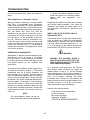
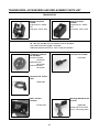
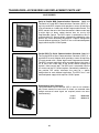
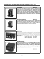
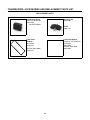
45 Transducers, Accessories and Replacement Parts List

ii
WARRANTY
WARRANTY:
Cutler Hammer-Eaton Corporation warrants all products against defects in material and work-
manship for a period of one (1) year from date of shipment to Buyer. This is a limited warranty limited to its
terms. This warranty is void if the product has been altered, misused, taken apart or otherwise abused. ALL
OTHER WARRANTIES, EXPRESS OR IMPLIED, ARE EXCLUDED, INCLUDING BUT NOT LIMITED TO
THE IMPLIED WARRANTIES OF MERCHANTABILITY AND FITNESS FOR PURPOSE.
BUYERS REMEDIES: Cutler Hammer-Eaton Corporation’s obligations and liabilities under the foregoing
warranty are limited to repair or replacement of the product without charge, provided it is mailed prepaid to
Cutler Hammer-Eaton Corporation, Durant Instruments, 901 South 12th Street, Watertown, Wisconsin,
53094. A charge is made for repairing after the expiration of the warranty. IN NO EVENT SHALL CUTLER
HAMMER-EATON CORPORATION BE LIABLE FOR CLAIMS BASED UPON BREACH OF EXPRESS OR
IMPLIED WARRANTY OR NEGLIGENCE OR ANY OTHER DAMAGES WHETHER DIRECT, IMMEDIATE,
FORESEEABLE, CONSEQUENTIAL OR SPECIAL OR FOR ANY EXPENSES INCURRED BY REASON OF
THE USE OR MISUSE, SALE OR FABRICATION OF PRODUCTS WHICH DO OR DO NOT CONFORM TO
THE TERMS AND CONDITIONS OF THIS CONTRACT.
INDEMNIFICATION: Buyer agrees to hold Cutler Hammer-Eaton Corporation harmless from, defend and
indemnify Cutler Hammer-Eaton Corporation against damages, claims and expenses arising out of subse-
quent sales of Durant products or products containing components manufactured by Cutler Hammer-Eaton
Corporation and based upon personal injuries, deaths, property damage, lost profits and other matters for
which Buyer its employees or sub-contractors are or may be to any extent liable, including without limitation
penalties imposed by the Consumer Product Safety Act (P.L.92-573) and liability imposed upon any person
pursuant to the Mansion-Moss Warranty Act (P.L.93-637), as now in effect or amended hereafter. The war-
ranties and remedies provided for herein are available to Buyer and shall not extend to any other person.
COMPLIANCE WITH OSHA: Cutler Hammer-Eaton Corporation offers no warranty and makes no repre-
sentation that its products comply with the provisions or standards of the Occupational Safety and Health Act
of 1970, or any regulations issued thereunder. In no event shall Cutler Hammer-Eaton Corporation be liable
for any loss, damages, fines, penalty or expense arising under said Act.
This manual constitutes proprietary information of Cutler Hammer-Eaton Corporation, and is furnished for the
customer’s use in operating the Series 5886 Count Control. Reproduction of this material for purposes other
than the support of the 5886 Control or related products is prohibited without the prior written consent of Cut-
ler Hammer-Eaton Corporation.
In the construction of the Control described herein, the full intent of the specifications will be met. Cutler Ham-
mer-Eaton Corporation, however reserves the right to make, from time to time and without prior written
notice, such departures from the detail specifications as may be required to permit improvements in the
design of the product.
The information included herein is believed to be accurate and reliable, however, no responsibility is assume
to Cutler Hammer-Eaton Corporation for its use; nor for any infringements of patents or other rights of third
parties which may result from its use.
WARNING:
This equipment generates, uses and can radiate radio frequency energy and if not installed
and used in accordance with the instructions manual, may cause interference to radio communications. It has
been tested and found to comply with the limits for a Class A computing device pursuant to Subpart J of Part
15 of FCC Rules, which are designed to provide reasonable protection against such interference when oper-
ated in a commercial environment. Operation of this equipment in a residential area is likely to cause interfer-
ence in which case the user at his own expense will be required to take whatever measures may be required
to correct the interference.

GENERAL DESCRIPTION
1
The Durant Model 5886 is a versatile six-digit,
three-preset, bi-directional count control. The con-
trol has three sets of transistor outputs (one for
each preset), and two relay outputs. The two
relays may each be operated by any of the three
transistor outputs. The three transistor outputs
may be programmed to occur sequentially or inde-
pendently with the count. Output 1 and/or Output 2
may also be programmed to function as floating
prewarn outputs. The control may be programmed
to reset to zero or reset to the preset 3 value.
The 5886-1400 Model also features the ability to
scale incoming counts. This means that for each
pulse received on the count inputs, a fraction or
multiple of that pulse is counted. The scale factor
can be a number from 0.0001 to 9.9999. This
number becomes a factor by which incoming
count pulses are multiplied.
A non-volatile memory insures that the setup
instructions will not be lost if power is interrupted.
Count values will also be retained if a power loss
interrupts a process or machine cycle.
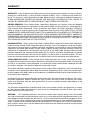
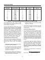
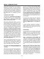
The front panel of the control, Figure 1, is framed
by a bezel that seals the panel to the mounting
surface. A large, six-digit high visibility red LED
display with a programmable decimal point posi-
tion is located in the upper left portion of the panel.
The keyboard has a Mylar front face and consists
of ten data keys (0 through 9), “COUNT” key,
“RESET” key, “FUNCTION” key and “ENTER” key.
The “1” key also serves as the “PRESET 1” key,
the “2” key also serves as the “PRESET 2” key
and the “3” key also serves as the “PRESET 3”
key. The upper right portion of the front panel con-
tains 4 yellow LED indicators for Count, Preset 1,
Preset 2, and Preset 3.
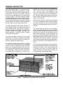
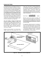
The rear panel, Figure 2, contains screw terminals
for use with stripped wire, either solid or stranded,
from 28 to 14 gauge. The rear panel also contains
two plug-in type replaceable relays with “form-C”
contacts.
The counter provides two-way serial communi-
cation with remote devices using standard ASCII
code and three selectable Baud rates. Count and
preset data can be sent and preset data and a
print request command can be received by the
control via two 20-milliampere current loops. On
Model 5886-1400 the Scale Factor may also be
transmitted and received. Optional accessories
are available to convert the communication loop to
RS232, parallel BCD and multiplexed BCD for-
mats.
The relay and transistor outputs can be timed from
0.01 to 99.99 seconds inclusive, latched until reset
complete, unlatched at reset, remain latched until
an unlatch input occurs or unlatch when the
counter reaches an alternate preset. Outputs can
also be operated in the Reverse mode.
Figure 1. 5886 Dual Preset 6-Digit Electronic Control

SPECIFICATIONS
2
Figure 2. 5886 Rear Panel
The count input circuit provides the user with sev-
eral options:
1. Separate add and subtract inputs.
2. Count input with up/down control input.
3. Quadrature input.
4. Count doubling in any of the three above con-
figurations.
5. Count up input with count inhibit input.
6. High or low speed operation. Low speed oper-
ation provides maximum immunity to contact
bounce and noise.
The control is equipped with self-diagnostics which
test the internal memories for faults. Should a fault
be detected, an indication given on the display.
Displays and indicators are turned on in a pat-
terned sequence for visual examination.

SPECIFICATIONS
3
POWER REQUIREMENTS:
AC Operation:
115/230 VAC (+10%, -20%) 47 - 63 Hz.
DC Operation:
11 - 28 VDC
Power:
18 Watts
DC POWER OUTPUT:
15 VDC (+1, -2).
150 mA if powered from AC or less than 24
VDC.
100 mA if powered from 24 VDC or greater.
NOTE: DC power output is only regulated if
unit is powered by AC or greater than 18.5
VDC.
ENVIRONMENT:
Operating Temperature:
32 to 130° F (0 to 55° C)
Storage Temperature:
-40 to 160° F (-40 to 70° C)
Operating Humidity:
85% non-condensing relative
PHYSICAL:
Case Dimensions:
5.38″ W × 2.62″ H × 5.91″ D
(136.7mm W x 66.5mm H x 150.1mm D)
Bezel Dimensions:
5.80″ W × 3.04″ H × 0.17″ 0
(147.3mm W × 77.2mm H × 4.3mm D)
LIP:
0.2″ (5.0mm)
Panel Cut-out Dimensions:
5.43″ W x 2.68″ H
(138mm W x 68mm H, DIN)
Mounting Panel Thickness:
0.58″ (14.7mm) maximum
(without optional spacer provided)
.077″ (1.96mm) maximum
(with optional spacer provided)
Front panel will provide watertight seal with
gasket provided.
Case Material:
Cadon FRX plastic case with Mylar front face
overlay
Weight:
2.2 lbs. (1.0 Kg)
Display Size:
6 digits, 0.56″ (14.2mm) H
(with programmable decimal point
location)
Memory Types:
PROM, RAM, Non-volatile NVRAM
COUNTER:
Count Range:
6 digits (0 to 999,999) with rollover
Preset Range:
6 digits (0 to 999,999) (3 presets)
Count Modes:
Count with Add and Subtract inputs
Count with Up/Down direction input
(Hardware doubling for above modes is
provided.)
Count with Count Inhibit input
Quadrature
Doubled Quadrature
Count Speed (Model 5886-0400):
0 to 7,500 CPS minimum for sensors with
open collector transistor output.
0 to 5,000 CPS when hardware doubling IS
implemented.
0 to 150 CPS when Low Frequency jumpers
are installed.
Count Speeds for Model 5886-1400 are shown
on page 28.

DESCRIPTION OF OPERATING MODES
4
COUNT INPUT RATINGS:
The count inputs are designed to work with
current sinking sensors (open-collector NPN
transistor output with or without passive pull-
up resistor) or contact closures to DC
Common.
Input Voltage:
High state (Logical “1”, sensor off or contact
open):
10.5 to 24.5 VDC when control is powered by
AC line
7.0 to 24.5 VDC when control is powered by 11
VDC
11.0 to 24.5 VDC when control is powered by
16 VDC
Low state (Logical “0”, sensor on or contact
closed):
0 to 4.5 VDC when control is powered by AC
line
0 to 3.0 VDC when control is powered by DC
supply
Input Impedance:
6800 ohms to 15 VDC when control is
powered by AC line
6800 ohms to 10 VDC when control is
powered by DC supply
Input Current:
20 mA peak, 3 mA steady state
Input Response:
High State (Logical “1”, sensor off or contact
open)
High Speed (Low Speed jumpers not
connected):
110 µsec minimum at 15 VDC (6,800 ohms to
+DC)
160 µsec minimum at 13.5 VDC (50,000 ohms
to +DC)
High State (Logical “1”, sensor off or contact
open)
Low Speed (Low Speed jumpers connected):
5.5 msec minimum at 15 VDC (6,800 ohms to
+DC)
7.5 msec minimum at 13.5 VDC (50,000 ohms
to +DC)
Low State (Logical “0”, sensor on or contact
closed)
High Speed (Low Speed jumpers not
connected):
20 µsec minimum at 0.1 VDC (0 ohms to DC
Common)
45 µsec minimum at 1.5 VDC (500 ohms to
DC Common)
Low State (Logical “0”, sensor on or contact
closed)
Low Speed (Low Speed jumpers connected):
1.0 msec minimum at 0.1 VDC (0 ohms to DC
Common)
2.0 msec minimum at 1.5 VDC (500 ohms to
DC Common)
CONTROL INPUTS:
Impedance:
4.75K ohms to +5 VDC.
Threshold:
High +3.5 to +22 VDC.
Low +0.0 to +1.0 VDC.
Response Time:
Min. High 5.3 mS.
Min. Low 3.9 mS.
NOTE: The reset and unlatch signals will both
occur in less than 200 microseconds after the
input signal is detected. The start of the print will
occur within 2 milliseconds after the input is
detected if the unit is not counting.
OUTPUT RATINGS:
Relay Contacts
Type: Form C (SPDT)
U.L./C.S.A. Contact Ratings:
10 amps, resistive, @ 24 VDC or 230 VAC
1/3 HP @ 115 VAC or 230 VAC
150 VDC maximum switched voltage
Mechanical Life: 5,000,000 operations
Electrical Life: 100,000 operations at resistive
rating

DESCRIPTION OF OPERATING MODES
5
Transistor Outputs
Type: Open collector NPN transistor with
Zener diode transient surge protection.
Load Voltage: 30 VDC maximum
Load Current: 300 milliamps maximum per
transistor. 480 milliamps total for all
transistors.
Rev. 50-59:
Use 90 milliamps per relay coil when
calculating total transistor current.
Rev. 60 - up:
Use 5 milliamps per relay coil when calculating
total transistor current.
OUTPUT OPERATING MODES:
Actuation:
Independent
Prewarn (Outputs 1 and 2 only)
Sequential
Unlatch:
After timeout
With external signal
When Reset Energized
When Reset De-energized
At Alternate Output
Reverse:
Reversed operation of any transistor outputs
COUNTER OPERATING MODES:
Reset to Zero
Reset to Preset
Auto Recycle
Maintained Reset
Momentary
DIAGNOSTIC MODES:
ROM Checksum
RAM Bit Test
NVRAM Read/Write Test
NVRAM Store Test
NVRAM Checksum
Watchdog Timer
Display and Led Indicator Test
COMMUNICATIONS:
Interface Type:
Dual port 20 milliamp current loop
Speed:
110, 300 and 1200 Baud, user selectable
Data Type:
Standard ASCII code
Format:
Start bit, 7 ASCII data bits, Parity bit, one or
two Stop bits
(Even parity for Serial Data Output, no
parity for Serial Data Input)
Information Transmitted:
Count value
Preset 1 value
Preset 2 value
Preset 3 value
Scale Factor (Model 5886-1400 only)
Information Received:
Print request
Preset 1 value
Preset 2 value
Preset 3 value
Scale Factor (Model 5886-1400 only)
SCALE FACTOR:
Range:
5 digits (0.0001 to 9.9999)

DESCRIPTION OF OPERATING MODES
6
COUNT MODES
The control has five count modes, which are:
Count with separate add and subtract inputs,
Count with direction control input, Count up with
inhibit control input, Quadrature, and Doubled
Quadrature.
Add and Subtract Inputs
The add and subtract mode allows separate sig-
nals to simultaneously add and subtract counts. It
can be used to indicate material stretch, subtract
defective parts from total parts produced, etc.
Count with Directional Control
Count with direction control mode uses one input
for incoming count pulses and the other to inform
the control whether the pulses should be used to
add or subtract counts. Count with direction may
be used when an item must be measured or posi-
tioned. Many types of sensors or control systems
utilize count signals of this nature.
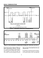
In both of the above count modes, the counter will
normally increment or decrement on the falling
edge of the incoming count pulse. (The falling
edge is defined as the moment in time when the
pulse changes state from +DC to DC Common
potential.) Doubling allows the counter to incre-
ment or decrement on both the falling and the ris-
ing edges of the pulse. (The rising edge is defined
as the moment when the pulse changes state from
DC Common to +DC potential.)
Count with Inhibit Control
The count up with inhibit control mode provides an
input which increments the control and an input
which causes incoming count pulses to be
ignored. This mode can be used when defective
material must be ignored or when inspection sam-
ples are taken without incrementing the counter.
The count up with inhibit control mode may not be
doubled.
Quadrature Inputs
Quadrature counting makes use of two count sig-
nals which are phase shifted by 90 degrees. The
detection of which signal is rising first allows the
counter to know in what direction the shaft is turn-
ing. When Quadrature count sources are being
used, the Double Input must always be connected
to DC Common to allow the quadrature signals to
be decoded.
Quadrature Input Doubled
Doubled Quadrature is implemented by program-
ming. This mode allows the counter to count on
both the rising and falling edges of the incoming
count pulses. The number of pulses per revolution
of the shaft encoder is effectively doubled,
increasing the resolution without any loss of accu-
racy.
COUNT SCALING
When the 5886-1400 receives a count pulse in any
count mode, the count is increased by the scale
factor for count-up pulses and decreased by the
scale factor for count-down pulses. The count
shows the accumulated total in whole increments.
Accumulated Total = Total Number of Pulses ×
Scale Factor.
DECIMAL POINT LOCATION
The location of the decimal point on the display is
programmed and may be located between any two
digits on the display, or omitted. When a printer is
connected to the serial communication output, the
decimal point is printed.
The decimal point remains on the display when-
ever the actual value of the counter or the preset
value is being displayed. It is not lit when function
codes or other function entries are being dis-
played. The timeout function automatically dis-
plays the decimal point to indicate 0.01 second
increments.
COUNTER OPERATING MODES
Reset Mode
Reset mode is used when the counter should start
at zero and count up to the preset values. Reset
mode implies that when the “RESET” key is
pressed or the Reset input in energized, the
counter is reset to zero.
Preset Mode
Preset mode is used when the control must start at
a preset value and count down to zero. Preset

DESCRIPTION OF OPERATING MODES
7
mode implies that when the “RESET” key is
pressed or the Reset input is energized, the con-
trol is reset to preset 3; that is, forced to have a
value equal to the preset 3 value. When the con-
trol is in the Preset mode, transistor output 3 turns
on when the counter reaches zero.
Automatic Recycle Operation
It may be desirable to have the control automati-
cally reset itself for repeated cycles. Auto Recycle
can be programmed to occur when any one, any
of two or any of the three transistor outputs turn
on. When in the Reset mode and any of the
selected outputs turn on, the counter is automati-
cally reset to zero. When in the Preset mode and
any of the selected outputs turn on, the counter is
automatically reset to the Preset 3 value.
OUTPUT AND RELAY OPERATION
The outputs of the control consist of five transis-
tors and two relays. The output associated with
Preset 1 and the output associated with Preset 2
each provide a pair of transistors. The two transis-
tors in each pair operate in parallel; that is, when
one of the transistors is turned on, the other is
turned on as well. The fifth transistor is associated
with Preset 3. The collectors of each of these tran-
sistors is brought out to individual screw terminals.
The relays are uncommitted and may be assigned
by the user to any of the 5 transistor outputs. This
is done by connecting a single wire for each relay
to the desired transistor output screw terminal.
When shipped from the factory, relay K1 is
prewired to Output 1 (terminal 8) and relay K2 is
prewired to Output 2 (terminal 9).
Turning Outputs On
There are three programmable modes which affect
when the transistor outputs turn on (conduct to DC
Common.) These modes are:
Independent Mode
Prewarn Mode
Sequential Mode
In addition, the reset and preset modes affect
when transistor output 3 turns on.
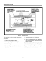
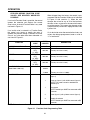
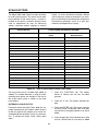
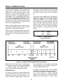
In the Independent and Prewarn modes, each out-
put turns on whenever the count reaches the value
specified in Figure 3. This occurs regardless of the
order in which the presets are reached. Note that
the Prewarn/Preset modes operate the same as
the Independent/Preset mode.
The Prewarn mode allows Output 1 and/or Output
2 to be programmed to turn on a specific number
of counts before Output 3. This mode is valid only
when the control is programmed to Reset to Zero.
In the Prewarn mode, Preset 1 and/or Preset 2 are
set to the number of counts before Output 3 at
which the Prewarn Output(s) are desired. When
Preset 3 is changed, the count values at which
Output 1 and/or Output 2 actuate (Prewarn Val-
ues) are also changed by the same amount. The
Prewarn Value(s) (Preset 3 minus Preset 1 or Pre-
set 3 minus Preset 2) may be displayed by
EVENT PROGRAMMABLE FUNCTION
Count Reaches
Independent Prewarn** Sequential
Prewarn 1 Prewarn 2 Prewarn 1 & 2
Reset Preset Reset Preset Reset Preset Reset Preset Reset Preset
Preset 1
Preset 2
Preset 3
Preset 3-Preset 1
Preset 3-Preset 2
Zero
1
2
3
1
2
3
2
3
1
1
2
3
1
3
2
1
2
3
3
1
2
1
2
3
1*
2*
3*
1*,2*,3*
“1”, “2”, or “3” indicates which output turns on. *Output turns on only if it is next in sequence.
**The Preset for a Prewarn Output must be less than Preset 3.
Figure 3. Output Actuation Table

INSTALLATION INSTRUCTIONS
8
selecting the appropriate Function Code (see Fig-
ure 22).
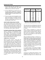
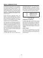
In the Sequential mode, each output turns on as
specified in Figure 3, only if that output is next in
sequence (see Figure 4). The counter automati-
cally resets and advances the sequence after the
first and second events shown in Figure 4. In the
Reset mode the counter is automatically reset to
zero, in the Preset mode the counter is automati-
cally reset to Preset 2 after the first event and Pre-
set 1 after the second event shown in Figure 4.
The counter does not automatically reset after the
third event unless automatic recycle is pro-
grammed to occur at that output. An automatic
recycle at any event resets both the counter and
the sequence. In the count mode, the Preset
LED’s light to show which Output is next in
sequence.
In the Sequential mode, the reset input or reset
key may be used at any time to reset both the
counter and the sequence. A separate program-
mable input (terminal 16) may be used at any time
to reset the counter without resetting the
sequence.
Turning Outputs Off
Once a transistor output is turned on, it remains on
until it is unlatched. There are five ways to unlatch
each output:
1. Timeout
Each output has a separate timeout function.
The timeout function causes an output to
unlatch after a specified “on” time. The allow-
able time range is from 0.01 to 99.99 seconds.
A value of 0 inhibits the timeout function for
that output. In this case, the output remains on
until unlatched by one of the following meth-
ods.
2. Unlatch at Reset (UAR)
Each output may be programmed to unlatch
when the reset key is pushed or the reset input
is energized (goes low).
3. Latch Until Reset Complete (LURC)
Each output may be programmed to unlatch
when the reset key is released or the reset
input is de-energized (goes high).
4. Unlatch at Alternate Output
Each output may be programmed to unlatch
when one or either of the remaining two out-
puts turns on.
5. Unlatch Inputs
Two programmable unlatch inputs may be
used to unlatch any two of the three outputs.
When an unlatch input is energized, the
selected output unlatches.
Figure 4. Output Sequence Table
Reverse Outputs
Each transistor output may be programmed to
operate in reverse. A reversed output is normally
on (conducts to DC Common) and turns off when
Figure 3 shows that it should turn on. Likewise, a
reversed output turns on when it is timed out or
unlatched.
When power is interrupted, all outputs turn off and
will remain off when power is reapplied. It is there-
fore necessary to “enable” all reversed outputs
after a power interruption. This is usually done by
energizing the appropriate unlatch input(s) or by
programming the reversed outputs to latch until
reset complete and then resetting the control.
,
,,
,
WARNING
A POWER OUTAGE CAUSES THE OUT-
PUTS AND RELAYS TO TURN OFF
REGARDLESS OF THE OPERATING
MODE SELECTED. BE SURE THAT
THIS EFFECT IS NOT HAZARDOUS TO
THE OPERATOR.
Event Sequential Mode
Reset Preset
First
Second
Third
Output 1
Output 2
Output 3
Output 3
Output 2
Output 1

INSTALLATION INSTRUCTIONS
9
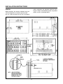
GENERAL
When mounting, the location selected must pro-
vide for adequate air circulation space around
the unit. Avoid locating the unit near instruments
and/or equipment that generate excessive heat.
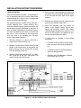
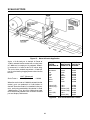
Figure 5 shows recommended cutout and product
details as well as mounting details.

INSTALLATION INSTRUCTIONS
10
WIRING - GENERAL
1. Disconnect all power before wiring terminals.
2. Do not use machine power service for 115/230
VAC input power to the control. A dedicated or
lighting circuit is recommended.
3. Keep all signal lines as short as possible.
4. Do not bundle or route signal line(s) with
power carrying lines.
5. Tools required are a wire stripper and a small
common screwdriver.
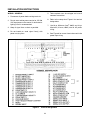
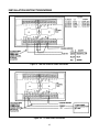
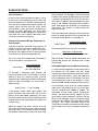
6. Refer to the setup chart Figure 6 for terminal
designations.
7. Use 18 ga. Minimum (1mm
2
, 600V) and 14 ga.
Maximum (2.1mm
2
, 600V) wire for AC power
wiring.
8. See Figure 8 for correct fuse to be used in the
power input wiring.
Figure 6. Terminal Designations

INSTALLATION INSTRUCTIONS
11
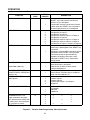
TERMINAL ASSIGNMENTS AND FUNCTIONS
#1 - BYPASS PRESET 1 INPUT
Connecting this terminal to DC Common causes
the counter to ignore Preset 1. When the counter
reaches Preset 1, Transistor Output 1 remains off
and any other functions (such as auto recycle at
Output 1) will not occur.
NOTE
:
In the sequential mode, this input must be
energized before the counter starts count-
ing to or from preset 1 for bypass to occur.
#2 AND 3 - TRANSISTOR OUTPUT UNLATCH
INPUTS
These two terminals are programmable inputs
which may be used to unlatch any two of the three
transistor outputs. Function code 49 is used to
select which output is unlatched by each input
(see Figure 21). When an Unlatch input is ener-
gized, the selected output turns off. If the output is
already off, the Unlatch input has no effect. If the
output has been reversed the Unlatch input turns
the output on.
#4 - BYPASS PRESET 2 INPUT
This input operates the same as #1 above except
it applies to Preset 2 and Transistor Output 2.
#5 AND 8 - TRANSISTOR OUTPUT 1
These outputs are open collector NPN transistors
with built-in transient overvoltage protection in the
form of zener diode clamping. Each transistor is
rated at 30 Vdc maximum and can sink up to 300
milliamps. Both transistors turn on as shown in
Figure 3 for Output 1.
#6 AND 9 - TRANSISTOR OUTPUT 2
These outputs have the same configuration as #5
and 8 above except that they turn on as shown in
Figure 3 for Output 2.
#8, 9, 12 AND 21 - DC COMMON
These terminals are internally connected to the
negative side of the DC power supply.
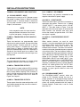
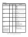
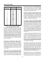
#10 AND 14 - COUNT INPUTS
These two count inputs are used to increment or
decrement the counter. Terminal #14 is labeled
“COUNT INPUT 1” and terminal #10 is “COUNT
INPUT 2.” The table shown in Figure 7 lists the
operation of the two count inputs as related to the
count function, and indicates how each input
causes the counter to operate when a DC Com-
mon signal is applied.
#11 AND 13 - LOW FREQUENCY SELECT
INPUTS
When contact closures are used for count
sources, it must be remembered that the contacts
will bounce slightly each time they close. This
slight bounce can cause extra counts to be
entered into the counter. This effect can be elimi-
nated by limiting the allowable frequency response
at the count inputs. The low frequency select ter-
minals reduce the count input frequency response
from 7500 PPS to 150 PPS when they are con-
nected to DC Common. Terminal #13 is LOW
FREQUENCY SELECT for COUNT INPUT 1 (ter-
minal #14) and terminal #11 is LOW FREQUENCY
SELECT for COUNT INPUT 2 (terminal #10). Low
frequency is selected by placing a jumper between
terminal #11 and/or terminal #13 and DC Com-
mon. Use the Low Frequency inputs whenever
possible to guard against electrical noise and
interference.
#15 - PROGRAM INHIBIT INPUT
The PROGRAM INHIBIT terminal, when con-
nected to DC Common through the use of a
jumper, prevents all of the programming functions
from being changed. Modification of the Preset
values can also be prevented with this jumper if
Function Code 41, Preset Lock, is set to a value
other than “0.”

INSTALLATION INSTRUCTIONS
12
Figure 7. Count Input Operating Modes
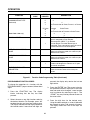
#16 - PRINT REQUEST/RESET COUNTER
INPUT
Terminal 16 is a programmable input which may
be used in one of two modes. Function Code 84 is
used to select the desired mode.
Print Request/Display Latch Mode
When terminal 16 is energized in this mode, the
data specified in Function Code 91 is transmitted
through the Serial Data Output terminals. The data
is transmitted once each time terminal 16 is ener-
gized.
In this mode, terminal 16 also serves to latch the
count value on the display while the control contin-
ues counting. The display remains latched until
terminal 16 is deenergized.
Reset Counter Mode
In this mode, terminal 16 is used to reset the
counter without resetting the output sequence. If
the control is not in the sequential mode, terminal
16 defaults to the Print Request/Display Latch
mode.
#17 - RESET INPUT
When terminal #17 is connected to DC Common
through an external switch, relay, or sensor, the
counter is remotely reset. If the counter is in the
Reset mode, energizing this input returns the
counter value to zero. If the counter is in the Pre-
set mode, the counter value is changed to the pre-
set 3 value. If the control is in the sequential mode,
the reset input also resets the sequence. If the
Unlatch At Reset or Latch Until Reset Complete
mode of operation is selected for any outputs, the
input unlatches the selected combination of tran-
sistor outputs in addition to resetting the control.
The Reset input has the same function as the front
panel “RESET” key.
#18 - DOUBLE INPUT
Connecting the DOUBLE INPUT to DC Common
selects count doubling for either the Add and Sub-
tract or the Count with Direction Control count
modes. When either Quadrature or Doubled
Quadrature count mode is selected, the Double
Input must be connected to DC Common for
proper operation.
#19 - BATTERY OR EXTERNAL 11-16 VDC
SUPPLY
The power source can be either an external bat-
tery (11 to 16 volts) or a 15 VDC power supply.
Connect this terminal to the positive side of the
external low voltage supply and a DC Common
terminal to the negative side.
#20 - 15 VDC POWER OUTPUT
This terminal may be used to power external
devices such as sensors, a shaft encoder, or indi-
cator lamps. The terminal supplies a regulated 15
VDC (+1V, -2V) to the loads at a maximum of 100
milliamps. The 15 VDC supply is generated only
when the unit is powered by 115 or 230 VAC.
#22 THROUGH 24 AND #29 THROUGH 31 -
RELAY CONTACTS
Each of the 2 internal relays provides a set of 5
amp resistive dry form “C” contacts (SPDT) rated
COUNT MODE
INPUT 1
(Term. #14)
INPUT 2
(Term. #10)
Separate add and subtract
Count up with inhibit control
Quadrature *
Count with up/down control
Doubled quadrature*
Subtract counts
Add counts
Input A
Count input
Input A
Add Counts
Inhibit counts
Input B
Up/Down control
Input B
*NOTE For both Quadrature modes, the wires to inputs #1 and #2 may be interchanged to reverse count
direction Terminal #18 must also be tied to DC Common (terminal #8 or #12) for proper quadrature oper-
ation.

INSTALLATION INSTRUCTIONS
13
at 115 or 230 VAC. For K1 terminal #23 is common
to terminal #22(NC) and terminal #24(NO). For K2
terminal #30 is common to terminal #29(NC) and
terminal #31(NO).
#25 THROUGH 28 - AC POWER INPUT
For 115 VAC operation, jumper terminal #25 to
#28, and #26 to #27. Connect the AC line power to
#25 and #26.
For 230 VAC operation, jumper #26 to #28. Con-
nect the AC line power to #25 and #27.
#32 - CHASSIS GROUND
This terminal must be connected to earth ground
to provide proper noise immunity. When shielded
cable is used for sensors or communications wir-
ing, connect the shields to this terminal.
When the unit is being used in a mobile, battery
powered application, this terminal MUST be con-
nected to CHASSIS GROUND.
A factory installed green wire connects this termi-
nal to DC Common. This is done to provide added
immunity to static discharge and electrical interfer-
ence. In control systems incorporating several
electronic devices, it is accepted practice to pro-
vide one SYSTEM grounding point. In this case,
the green wire as provided may be removed and
SEPARATE green wires attached to both Chassis
Ground and DC Common for connection to the
common system grounding point.
For applications which require isolated DC Com-
mon and Chassis Ground, the green jumper may
be removed entirely. However, extra care must be
taken to route current carrying wires away from the
counter as much as possible. Shields in trans-
ducer cables should be connected to Chassis
Ground wherever possible.
#33 AND 34 - SERIAL DATA INPUT
The serial communications inputs are used to
receive new preset values and print requests. The
interface utilized is a standard 20 milliamp current
loop with a user selectable Baud rate.
Terminal #33 is the negative side of the current
loop and #34 is the positive side. When connecting
serial communications between the unit and any
other device, note that SERIAL DATA OUT PLUS
(SDO+) from the transmitting device is wired to the
SERIAL DATA IN MINUS (SDI-) of the counter.
Likewise, SDO- from the transmitting device is
wired to SDI+ of the counter.
#35 AND 36-SERIAL DATA OUTPUT
The counter has serial communications output
which may be used to transmit the current count
value, the preset 1 value, the preset 2 value, the
preset 3 value, or any combination. The Baud rate
of the 20 milliamp current loop is user selectable.
However, the Baud rate selected is the same for
serial input and serial output communications.
Terminal #36 is the negative side of the output cur-
rent loop and terminal #35 is the positive side.
When connecting serial communications between
the counter and any other device, note that
SERIAL DATA OUT PLUS (SDO+) from the
counter is wired to the SERIAL DATA IN MINUS
(SDI-) of the device receiving the data. Likewise,
SDO- from the counter is wired to SDI+ of the
receiving device.
RELAY COIL LEADS
The gray lead is internally connected to the K1
relay coil and the white/yellow lead is internally
connected to the K2 relay coil. As shipped from
the factory, the gray lead (K1) is connected to Out-
put 1 (terminal 8) and the white/yellow lead (K2) is
connected to Output 2 (terminal 9). These termi-
nals conduct to DC common when energized. The
opposite side of each relay coil is internally con-
nected to +12 Vdc.
INTERCONNECTION
After determining the desired operating mode,
select the appropriate Figure 8 through 21 for con-
nection diagrams for the application.

INSTALLATION INSTRUCTIONS/WIRING
14
PANEL MOUNTING
The panel mounting kit includes: (1) mounting gas-
ket, (2) mounting clips and (2) screws. Refer to the
dimension diagram in Figure 5 for a drawing of the
correct installation of these parts.
The mounting gasket is coated on one side with a
contact adhesive and a paper backing. Care
should be taken during the gasket installation that
the gasket be correctly positioned on the panel at
the first attempt. Attempting to re-position the gas-
ket once the adhesive has come in contact with
the panel is likely to deform or tear the gasket.
This may result in an improper seal. For best
results, follow these directions:
1. Stand the counter on a desk or table with its
display down, screw terminals up.
2. Remove and discard the center square of the
gasket at the scribe marks in the gasket and
paper backing. Do not remove the backing
from the remaining outer rim.
3. Slide the gasket down the unit until it is in posi-
tion at the rear of the unit’s front bezel. The
paper backing side should be up.
4. Insert the tip of a knife between the paper and
the gasket and, while holding the gasket down
to the unit with the knife, peel off the paper
backing.
5. Slide the unit through the panel cutout until the
gasket firmly adheres to the panel.
6. Install the mounting clips and screws as
shown in the diagram above. Do not over
tighten the mounting screws. The screws
should be tight enough to firmly hold the unit in
place, but not so tight as to squeeze the gas-
ket out from behind the front bezel.
7. A switch shall be included in the building
installation:
• It shall be in close proximity to the equip-
ment and within easy reach of the opera-
tor.
• It shall be marked as the disconnecting
device for the equipment.
• Switches and circuit breakers in Europe
must comply with IEC 947.
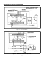
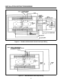
Figure 8. 115 VAC 47/63 Hz Power Connection

INSTALLATION INSTRUCTIONS/WIRING
15
Figure 9. 230 VAC 47/63 Hz Power Connection
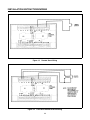
Figure 10. 12 VDC Power Connection

INSTALLATION INSTRUCTIONS/WIRING
16
Figure 11. Count Input Wiring
Figure 12. Quadrature Encoder Count Input Wiring

INSTALLATION INSTRUCTIONS/WIRING
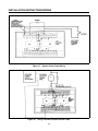
17
Figure 13. Encoder with Directional Control Count Input Wiring
Figure 14. Add and Subtract Count Input Wiring

INSTALLATION INSTRUCTIONS/WIRING
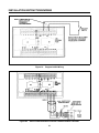
18
Figure 15. Remote Reset Wiring
Figure 16. Latch Until Contact Closure Wiring
Page is loading ...
Page is loading ...
Page is loading ...
Page is loading ...
Page is loading ...
Page is loading ...
Page is loading ...
Page is loading ...
Page is loading ...
Page is loading ...
Page is loading ...
Page is loading ...
Page is loading ...
Page is loading ...
Page is loading ...
Page is loading ...
Page is loading ...
Page is loading ...
Page is loading ...
Page is loading ...
Page is loading ...
Page is loading ...
Page is loading ...
Page is loading ...
Page is loading ...
Page is loading ...
Page is loading ...
Page is loading ...
Page is loading ...
Page is loading ...
Page is loading ...
-
 1
1
-
 2
2
-
 3
3
-
 4
4
-
 5
5
-
 6
6
-
 7
7
-
 8
8
-
 9
9
-
 10
10
-
 11
11
-
 12
12
-
 13
13
-
 14
14
-
 15
15
-
 16
16
-
 17
17
-
 18
18
-
 19
19
-
 20
20
-
 21
21
-
 22
22
-
 23
23
-
 24
24
-
 25
25
-
 26
26
-
 27
27
-
 28
28
-
 29
29
-
 30
30
-
 31
31
-
 32
32
-
 33
33
-
 34
34
-
 35
35
-
 36
36
-
 37
37
-
 38
38
-
 39
39
-
 40
40
-
 41
41
-
 42
42
-
 43
43
-
 44
44
-
 45
45
-
 46
46
-
 47
47
-
 48
48
-
 49
49
-
 50
50
-
 51
51


Eaton Cutler-Hammer Durant PRESIDENT Series Operating instructions
- Type
- Operating instructions
- This manual is also suitable for
Ask a question and I''ll find the answer in the document
Finding information in a document is now easier with AI
Related papers
-
Eaton Durant Eclipse 5775X-41 Series Operating instructions
-
-
-
Eaton E5-648-C242 Series Instruction Leaflet
-
-
-
