Eaton Power Xpert PXES4P Series Installation and User Manual
- Category
- Network switches
- Type
- Installation and User Manual
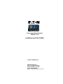
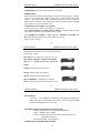
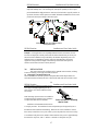
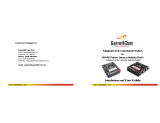
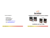
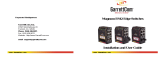
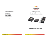
Eaton Power Xpert PXES4P Series are four-port, 10/100 Mb/s Ethernet switches designed for use in harsh environments. They are NEBS Level 3 compliant and meet IEEE 1613 standards for electrical power substations. The switches are also designed to meet IEC 61850 EMC and operating conditions Class C for power substations.
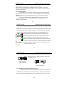
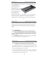
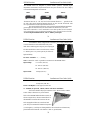
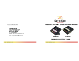
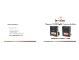
The PXES4P Series switches are equipped with three RJ-45 ports on the front and one RJ-45 port on the rear. They support both 10BASE-T and 100BASE-TX Ethernet standards and feature auto-negotiation and auto-MDIX capabilities. The switches also have dual LEDs for each port, indicating link status, activity, and speed.
Eaton Power Xpert PXES4P Series are four-port, 10/100 Mb/s Ethernet switches designed for use in harsh environments. They are NEBS Level 3 compliant and meet IEEE 1613 standards for electrical power substations. The switches are also designed to meet IEC 61850 EMC and operating conditions Class C for power substations.
The PXES4P Series switches are equipped with three RJ-45 ports on the front and one RJ-45 port on the rear. They support both 10BASE-T and 100BASE-TX Ethernet standards and feature auto-negotiation and auto-MDIX capabilities. The switches also have dual LEDs for each port, indicating link status, activity, and speed.


-
 1
1
-
 2
2
-
 3
3
-
 4
4
-
 5
5
-
 6
6
-
 7
7
-
 8
8
-
 9
9
-
 10
10
-
 11
11
-
 12
12
-
 13
13
-
 14
14
-
 15
15
-
 16
16
-
 17
17
-
 18
18


Eaton Power Xpert PXES4P Series Installation and User Manual
- Category
- Network switches
- Type
- Installation and User Manual
Eaton Power Xpert PXES4P Series are four-port, 10/100 Mb/s Ethernet switches designed for use in harsh environments. They are NEBS Level 3 compliant and meet IEEE 1613 standards for electrical power substations. The switches are also designed to meet IEC 61850 EMC and operating conditions Class C for power substations.
The PXES4P Series switches are equipped with three RJ-45 ports on the front and one RJ-45 port on the rear. They support both 10BASE-T and 100BASE-TX Ethernet standards and feature auto-negotiation and auto-MDIX capabilities. The switches also have dual LEDs for each port, indicating link status, activity, and speed.
Ask a question and I''ll find the answer in the document
Finding information in a document is now easier with AI
Related papers
-
Eaton PXESDINRL Installation and User Manual
-
-
-
-
-
-
-
-
Eaton BR115AFCS User guide
-
Other documents
-
Abocom SW800 User manual
-
 GarrettCom S14 User manual
-
GarrettCom Magnum S14 User manual
-
 GarrettCom CS14 User manual
-
 GarrettCom CSG14 User manual
-
 GarrettCom MAGNUM CSG14U User manual
-
 GarrettCom CSG14U User manual
-
 GarrettCom ES42 User manual
-
Dante DFG48044X Operating instructions
-
 GarrettCom P62 User manual


