
Operator’s Manual & Parts List
Compression Sprayers: 454, 456, 456 SW, 457,
454HD, 456HD, 457HD, 454V, 456V, 457V, 407CI
US9456702 (04-08)
year
warranty
WARRANTY:
Solo model 454, 456, 456 SW & 457 sprayers are covered by Solo’s 5-YEAR LIMITED WARRANTY. Solo manufactured parts which
fail due to defective material or workmanship will be repaired or replaced without charge. See page 6 for full details.
SAFETY PRECAUTIONS:
Do not exceed 45 psi pressure.
Do not fill with, use or spray flammable materials.
Do not use gasoline, acid, caustic or potentially injurious chemicals.
At the time of manufacture of this sprayer, we are not aware of any approved plant protection chemicals which
would adversely affect this sprayer when applied in their usual concentration.
Observe the recommendations of the chemical manufacturer.
Prior to removing any part of the sprayer pull the pressure relief valve to release any pressure in the tank.
Wear rubber gloves, safety goggles and appropriate protective clothing.
After pumping be sure handle is in the locked down position.
Individuals should be trained in the proper use of this sprayer. Where training is not available, individuals
should study and follow the procedures detailed in this manual.
Do not use acetone based chemicals.
WARNING:
Chemicals can be harmful to individuals and the environment if improperly used. In addition, some chemicals are caustic, corrosive, or
poisonous and should be avoided. Read warnings and chemical manufacturer’s instructions. Solo high density polyethylene sprayers
are fitted with Viton
®
seals which are resistant to a wide variety of agricultural, industrial and household chemicals; however, care
should be exercised to ensure that sprayer components are clean, functioning properly, and in a good state of repair before and during
use. If in doubt about a particular chemical, check with manufacturer. If you suspect or observe indications that the material may be
unsafe in a Solo sprayer... STOP! Do Not Use or Apply Chemical. ALWAYS WEAR RUBBER GLOVES, SAFETY GOGGLES AND
APPROPRIATE PROTECTIVE CLOTHING.
Read and follow operating instructions.
Do not fill sprayer over maximum fill mark. Releasing pressure in an overfill condition can cause harmful venting of sprayer contents.
Relieve pressure only with sprayer upright and while standing on the side of the sprayer opposite the pressure relief valve. Venting
of sprayer contents can occur if liquid is over bottom of relief valve.
CAUTION: To prevent injury from ejected pump assembly and/or solution, never stand with face or body over the top of the tank
when pumping, or loosening pump.
Do not modify sprayer or pressure relief valve.
Never spray in the direction of humans, animals or property which might be injured or
damaged by spray formula.
Do not use disinfectants, solvents or impregnating agents unless first tested to ensure
they are not harmful to the environment and sprayer.
Do not use liquids with a temperature above 120°F (45°C).
Remember that a sprayer with liquid is a significant amount of weight (8 lbs. per
gallon). Use caution when bending, leaning or walking. Bend only at the knees and
support yourself as required to ensure personal safety.
Do not inflate sprayer without liquid in the tank.
Do not climb on ladders, trees or other unsteady or potentially unsafe structures.
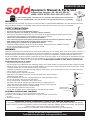
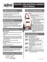
ASSEMBLY INSTRUCTIONS FOR WAND
1. Ensure that the O-ring is on the non-threaded end of the wand.
2. Insert the non-threaded end of the wand into the O-ring into the open end of the shut-
off valve.
3. Tighten the screw cap.
•
•
•
•
•
•
•
•
•
•
•
•
•
•
•
•
•
•
•
•
•
CUSTOMER SERVICE COMMITMENT FROM SOLO’S SERVICE DEPARTMENT
In the event the sprayer you have purchased has missing or damaged parts, please call 1-800-765-6462, 9:00 AM—5:00 PM EST.
In order to assist your service representative, please have the following information available: sprayer model number, part description
and part number. A parts list is included in your operator’s manual.
Solo is committed to your satisfaction and is continuing its efforts to earn your future business.
Visit us on the web at www.solousa.com
Troubleshooting and parts ordering available online.
Optional Pressure
Gauge Mounts Here
Screw Cap
Wand
Install Wand Here
O-Ring
Shut-Off Valve
STOP!
If you are missing parts, instructions or have questions, DO NOT take this unit back to the
store. Call 1-800-SOLO-INC. Solo will send the missing parts/information to you promptly.

2
CLEANING:
Carefully clean sprayer after every use.
Pour or spray all remaining chemical out of sprayer.
Pour a small amount of water for water soluble chemicals, or
mineral spirits for oil-based chemicals, into the tank.
Pressurize and spray through system until all liquid is gone.
Repeat process with warm soapy water.
Repeat process with warm clear water.
Use an absorbent cloth to dry all internal surfaces.
Follow the recommendations of the chemical manufacturer for
disposing of waste water and chemicals.
Do not use aggressive or abrasive cleaning agents.
•
•
•
•
•
•
•
•
•
USING THE ADJUSTABLE NOZZLE
To change the spraying pattern, first make sure the retaining nut
(2) is screwed tight to the elbow (5). If it is not tight, the nozzle
cap (1) and nozzle body (3) will
rotate inside the retaining nut and
the nozzle will not adjust. For a
straight stream pattern, rotate the
nozzle cap outward. For a hollow
cone pattern, rotate the nozzle cap
inward towards the retaining nut.
If it becomes difficult to rotate the
nozzle cap, remove the nozzle cap
from the nozzle body and lubricate
the O-ring on the nozzle body with
a non-water soluble grease*.
REMOVING ADJUSTABLE NOZZLE
Unscrew the nozzle cap (1) from the nozzle body (3). This
is best accomplished while the retaining nut (2) is securely
fastened to the elbow (5). Next, unscrew the retaining nut (2).
Push the nozzle body (3) out of the retaining nut (2). The filter
(4) will come out with the body. To re-install the nozzle, reverse
the above instructions.
OPERATION:
Before using sprayer with chemicals, fill sprayer with fresh
water to assure that you have it properly assembled;
pressurize and then practice spraying. When thoroughly
familiar with sprayer operation, follow normal operating
procedures.
Turn pump handle counter clockwise to remove pump.
Fill tank with premixed formula up to desired level. (Do not
exceed maximum fill mark.) Observe recommendations of
chemical manufacturer.
Tighten cap and pump assembly for a good seal.
Pump to a maximum 45 psi or 3 bar pressure. The valve
stem on the pressure relief valve will rise up to vent excess
pressure over 45 psi.
Start or stop spraying by squeezing or releasing the lever on
the shut-off valve (3). The spray pressure can be monitored
with an optional pressure gauge.
Prior to every removal of pump (1), release pressure first by
pulling up on the pressure relief valve stem (2).
•
•
•
•
•
•
•
* Solo Superior Grease or petroleum jelly work well.
1. Nozzle cap
2. Retaining nut
3. Nozzle body
4. Filter with gasket
5. Elbow
3
2
1
Tank Cap: A small amount of non-water soluble grease*
on tank cap threads and both sides of the gasket eases
tightening and loosening.
Regular Inspection: Inspect and replace worn or damaged
parts promptly. Pay particular attention to tank cap gasket,
pressure relief valve and seal, inflation valve (if fitted),
umbrella valve O-rings and seals throughout sprayer. Regular
lubrication of O-rings and seals is recommended.
•
•
MAINTENANCE:
Prior to storage, empty, clean and dry sprayer.
Always store the sprayer in a dry area, protected from
freezing, heat and sunlight.
Lubricate O-ring in pressure relief valve with non-water
soluble grease* on a regular basis.
•
•
•
Disassembly: Unscrew pump assembly from tank.
Carefully remove umbrella valve (6) from the bottom of
cylinder (3). While holding cylinder firmly with one hand
and the handle of the pump piston (4) firmly in the other,
with the piston fully inserted in the cylinder, pull back on
the piston quickly and forcefully. To re-assemble, place
the piston assembly back into cylinder, place heel of
hands on opposite sides of the tank cap, while keeping
cylinder in place with fingers, tap bottom of cylinder
against a flat padded surface. Assembly will lock into
place.
Disassembly: Unscrew pressure relief valve from tank
and pull the valve body out of the screw cap. Clean,
lubricate, and replace.
Pump Maintenance: Pump pressure sealing is accomplished
with an O-ring (5) on the pump piston (4) which moves within
the cylinder (3). Periodically this O-ring should be greased
with a non-water soluble grease*. If worn, it should be
replaced. A small umbrella valve at the bottom of the cylinder
prevents the formula from entering the cylinder. Keep these
parts clean and replace if worn.
•
6

OPERATING FEATURES:
Nozzles - Your Solo sprayer is standard with nozzle arrangements which provide a variety of spray patterns.
3
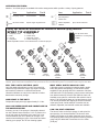
Spray tips should be assembled as follows for desired spray patterns.
SPRAY TIP ASSEMBLY
1. Flat spray nozzle 5. Nozzle cap
2. Filter 6. Nozzle body
3. Jet cap 7. Brass adj. nozzle*
4. Swirl plate 8. Nozzle retaining nut
*Brass adjustable nozzle is not a standard item on all Solo sprayers.
WILL THE PLASTIC MATERIAL LAST?
Only high-grade polyethylene is used. The material is
chosen for high molecular weight, high-impact strength,
and excellent resistance to chemicals and stress.
Ultraviolet inhibitors are used in the material to reduce
deterioration caused by sunlight.
HOW HEAVY IS THE UNIT?
Compression sprayers weigh approximately 5 1/2 lbs.
CAN I USE WEED KILLER AND INSECTICIDE IN
THE SAME SPRAYER?
In theory you can, if the sprayer is thoroughly cleaned
out with a bleach water solution of 1:25. In practice, the
use of both types of chemicals in the same unit is not
recommended as the risk to plants can be high. Use
caution when handling any type of chemicals and when
cleaning your sprayer. Do not mix cleaning agents.
WHAT SPRAY NOZZLE SHOULD I USE?
A flat spray nozzle is supplied for spraying paths, garden
beds, and general area spraying. A cone nozzle is also
supplied for spot spraying and for the treatment of bushes
and small trees. For spot spraying, simply remove swirl plate
from behind nozzle tip. Save the swirl plate for future use.
Available as an option is a reflux filter with a built-in check
valve (27 00 316) which opens at 5 psi and closes at 4 psi.
This virtually eliminates the dripping of fluid still contained
in the spray wand. A wide selection of nozzles such as
deflector, adjustable, and anti-drift nozzles are available.
CAN I DO SPOT SPRAYING?
The shut-off valve on the Solo sprayer is well suited for
spot spraying. It’s almost effortless! The shut-off valve
handle incorporates a clip which holds the valve open for
area spraying without tiring the operator’s hand. A pressure
gauge may be added with increments from 0 to 6 Bar
(0-90 psi).
In the best interest of continued technological progress, we reserve the right to change design and configuration of any product without prior or other notice.
Therefore, please note that text and illustrations of this manual are not to be considered binding and do not constitute a basis for legal or other claims.
Flat spray nozzle Row treatment 4074263
Item Application Part #
Jet stream nozzle Shrubs and bushes 4074755
and swirl plate =
hollow cone
Jet stream nozzle Spot & longer range 4074755 Plastic adjustable Spot, shrubs & bushes
4900527
Item Application Part #
Flat spray Hollow
cone spray
Brass
adjustable
nozzle*
Jet stream Plastic
adjustable
nozzle
No-drip-check valve
replaces # 2 on heavy-duty
models

4
Note: Always wear rubber gloves, safety goggles and appropriate protective clothing when repairing a sprayer.
Once a repair is completed, fill the unit with clean water, pressurize, and check for leaks. If the sprayer leaks,
DO NOT USE. Repair leaks and re-check.
SERVICE AND REPAIR SECTION
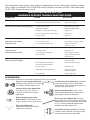
HANDHELD SPRAYER TROUBLE SHOOTING GUIDE
ACCESSORIES:
The following accessories are not standard. Order them from your Solo dealer.
Pressure control gauge (#49 00 322):
displays spraying pressure so operator
can maintain desired pressure level.
Pressure limiting valve (#49 00 183):
limits pressure to 5 psi, 10 psi or
15 psi as needed for low pressure
applications.
Brass adjustable spray nozzle
(#06 10 410-P): affords operator a full
range of sprays from fine to jet stream.
Drift guard (#49 00 430):
helps control application of formula
under breezy conditions.
2-nozzle spray boom (#49 00 514): handheld
spray boom mounts on end of spray wand
(total width 33”; distance between nozzles 24”).
Includes 2 flat spray nozzles.
Double nozzle (#49 00 477): this is a multi-
purpose nozzle that attaches to the end of the
spray wand for double row application.
Brass spray wand (#49 00 528): The 2 pcs
spray wand is 60” (150 cm) long and replaces the
standard spray tube for treating trees up to heights
of 16 ft. (5 meters). Additional extension tube
available in 20” length (#49 00 513).
Controlled Flow Valve (CFValve™): Provides
constant pressure and flow to the spray nozzle
and can be used in various applications.
Difficulty in moving pump handle • dirty cylinder wall • remove piston, clean, grease and replace
• O-ring on piston swollen (not cleaned properly) • replace O-ring, grease
Low pressure & resistance during pumping • No lube on piston/cylinder • lubricate with heavy grease
• Chemical in cylinder • Replace umbrella valve
•
Damaged O-ring in pressure relief valve • replace O-ring
• worm or damaged O-ring in shut-off valve • replace O-ring
• tank cap not tight • tighten cap
Leaks from end of spray wand • worn or damaged O-ring in shut-off valve • rebuild shut-off valve
Leaks from inside cylinder • no lube on piston cylinder • lubricate piston, O-ring and cylinder
Leaks under cap • worn or damaged umbrella valve • replace umbrella valve
at bottom of cylinder
Leaks from shut-off valve • damaged or missing gasket • replace gasket
Leaks from hose • screw cap not tight • tighten tank cap
Pressure relief valve sticks • worn, damaged or loose fittings, • tighten fittings and replace
lack of lubrication worn parts, disassemble and
lubricate O-rings
Air leak - air coming out between • worn, damaged or loose fittings • tighten fittings and the two.......
halves of the pump support replace worn parts
• lack of lubrication or contaminated • clean and lubricate pressure
relief valve relief valve assembly
• tank cap not tight • tighten tank cap
• gasket twisted or lacking lubrication • straighten gasket and
lubricate with grease
• tank lip damaged • repair or replace tank
PROBLEM CAUSE SOLUTION

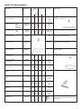
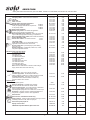
Nozzle Tip Specifications
Description Order number Spray Pressure Angle Applications
volume
US gal at
1/min /min atm psi
Flat Spray nozzle 4074263 0.88 .23 1.0 15 120° area and row treatment
1.25 .33 2.0 29 120°
1.53 .40 3.0 44 120°
Flat spray nozzle -brass 0065210 0.46 .12 1.0 15 80°
-plastic with 0065132 0.64 .17 2.0 29 80°
stainless 0.78 .21 3.0 44 80°
steel insert
Adjustable nozzle -brass 4900207 1.53 .40 2.8 40 Straight stream tree spraying (adjustable spraying pattern)
-plastic 4900527 0.76 .20 2.8 40 Hollow cone
Full cone nozzle 0065212 30°-50° game repellents of high viscosity
Full cone nozzle 0065213 30°-50° game repellents of low viscosity
Full cone nozzle 0065214 game repellents
Hollow cone nozzle 4900209 0.4 .10 1.0 15 shrubs, bushes
1 mm orifice 0.55 .15 2.0 29
Hollow cone nozzle 4900252 0.64 .17 1.0 15 50°
1.4 mm orifice 0.91 .24 2.0 29 65°
1.11 .29 3.0 44 65°
Hollow cone nozzle 4900322* 0.88 .23 1.0 15 55°
1.8 mm orifice 1.25 .33 2.0 29 70°
1.53 .40 3.0 44 72°
No-drift nozzle 4074383 0.23 .06 1.0 15 90° mainly for herbicides at low pressure
AN 0.5
No-drift nozzle 4074385 0.28 .07 0.4 6 100°
AN 1.0 0.38 .10 0.7 10 100°
0.46 .12 1.0 15 100°
No-drift nozzle 4074386 0.55 .15 0.4 6 100°
AN 2.0 0.76 .20 0.7 10 100°
0.91 .24 1.0 15 100°
Non-drift nozzle 4074514 0.72 .19 0.4 6 110°
AN 2.5 0.95 .25 0.7 10 110°
1.14 .30 1.0 15 110°
No-drift nozzle 4074513 1.80 .48 0.4 6 120°
AN 5.0 1.90 .50 0.7 10 120°
2.28 .60 1.0 15 120°
Foam nozzle 4900397 0.76 .20 3.0 45
0.90 .23 4.0 60
1.01 .26 5.0 75
1.10 .29 6.0 90
5
The XAN 2 nozzle is suited for low drift and
water saving application of herbicides which
tend to foam

6
SOLO LIMITED WARRANTY
Solo Incorporated guarantees the original purchaser of Solo equipment, that any failure of Solo
manufactured parts due to defects in material and workmanship occurring during the applicable
warranty period will be repaired or replaced without charge for parts or labor, except for those items
not covered by warranty.
CONSUMER LIMITED WARRANTY: Solo equipment purchased for consumer use is covered by this Limited Warranty
for a period of FIVE (5) YEARS.
COMMERCIAL LIMITED WARRANTY: Solo equipment purchased for commercial use is covered by this Limited Warranty for
a period of ONE (1) YEAR.
OPERATOR’S OBLIGATION AND RESPONSIBILITY: proof of purchase must be provided by the owner in order to obtain
warranty service. Should any failure covered by this Limited Warranty occur, deliver or ship the Solo products or parts to an
authorized Solo service center. Freight, packing and insurance costs, if any, will be borne by the owner. Follow normal maintenance
service to include applicable lubrication, operation and storage of the product as explained in the owner’s manual.
ITEMS NOT COVERED BY WARRANTY: provisions of the Limited Warranty will not apply to the following: Any indirect or
consequential damages that may result from the failure or malfunction of the Solo product. Normal service requirements arising
during the warranty period, such as cleaning, normal wear, lubrication, filter, spray tips, etc. Normal service work over and above
the repair or replacement of defective parts. Any failure that results from an accident, customer abuse, normal wear, neglect or
failure to operate the product in accordance with the instructions provided in the operator’s manual or provided with the product.
When an alteration or modification has been performed on a Solo product, Solo is responsible only for products as originally
furnished by Solo, provided the alterations or modifications do not adversely affect the product’s operation, performance or
durability. Parts or accessories that are incomplete with the product are not approved by Solo.
Full disclosure of Solo’s Limited Warranty is available from your local Solo dealer or Solo Incorporated, 5100 Chestnut Avenue,
Newport News, Virginia 23605.
This Limited Warranty gives you specific legal rights and you may also have other rights which vary from state to state.
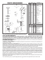
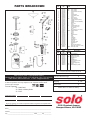
PARTS BREAKDOWN
Prices and technical specifications are subject to change without notice.
Pos. Order For Description
No. No. Model
Pos. Order For Description
No. No. Model
1 4071262 456 Tank, 2 gallon
- 4071267 454 Tank, 1 gallon
- 4071263 457 Tank, 3 gallon
2 4800185 Pressure relief valve assy.
3 0062166 * O-ring
4 0062115 * O-ring
5 4300245 Carrying strap
6 4073835 Pump piston, solid
7 0062264 * O-ring
10 4073528 Tank cap, red
- 4073111 HD Tank cap, black
11 4074387 Cylinder support (need 2)
12 4073834 Cylinder
- 4073834 Cylinder (use with 0094308)
13 4061345 * Gasket
14 4074656 * Valve cone
15 0062165 * O-ring
16 4900515 *** Pressure hose, assy.
17 4800170 Shut-off valve, assy.
18 4074295 Pin retaining
19 0062144 * O-ring
20 4900230 Wand, assy. (inc. 35 & 21A)
4900645 456SW Stainless Wand
21 0062271 O-ring
21A 0062258 O-ring
22 4074527 Elbow
23 0094308 * Umbrella valve
24 4074283 Filter
25 0062106 O-ring
26 4074756 Swirl plate
27 4074755 Jet cap tip
28 4074148 Retaining nut
29 4074329 Lock clip
33 4074263 Flat spray nozzle
47 4074336 Retaining nut
48 4074335 Lever
49 0610402-K Shut-off valve repair kit
52 4900527 Plastic adj. nozzle (incl. a & b)
4900207 456SW Brass adj. nozzle
- 4900405-K Pump repair kit
25 0062106 HD O-ring
30 4074726 ** Hollow cone nozzle
34 2700316 HD No drip check valve
35 4074337 Retaining nut
41 0062249 O-ring
42 4074338 Retaining nut
43 4065189 Pressure gauge guard
44 4900430 Drift guard
45 4900622 Pressure gauge assy.
50 0062115 HD O-ring
53 0065210 HD Brass flat spray nozzle
Accessories
* Pump repair kit ** Organic liquid spray kit
***Cut pick-up tube to fit for models 454 and 456

7
Item Names/Description Part No. Retail Price Qty. Total
Nozzles
Flat spray nozzle - surface area & row treatment 40 74 263 2.00
Jet cap 40 74 755 1.50
Swirl plate 40 74 756 1.50
Filter - standard 40 74 283 2.56
Sprayer elbow and nozzle assortment 06 10 408-P 14.95
No-drift wide angle flat nozzles - .60 GPM 40 74 513 2.50
mainly for spraying herbicides at low pressure. .30 GPM 40 74 514 2.50
At 15 psi they deliver: .24 GPM 40 74 386 2.50
.12 GPM 40 74 385 2.50
Elbow nozzle assembly 49 00 258N 6.35
Double spray nozzle - for double row application 49 00 477 24.95
spraying in two directions simultaneously.
Brass adjustable spray nozzle kit - with O-ring and screw 06 10 410-P 8.75
cap for tree spraying (from fine misting to a jet stream).
Brass adjustable spray nozzle (same nozzle as kit above) 49 00 207 6.25
Plastic adjustable nozzle 49 00 527 4.25
Hollow cone nozzles - for shrubs & bushes: 1.4 mm 49 00 252 2.85
1.8 mm 49 00 322 2.85
Jet stream nozzle 40 74 758 1.50
Foam spray nozzle - for low drift & water saving 49 00 397 9.95
application of herbicides which tend to foam.
No drip check valve - prevents spray tip from leaking 27 00 316 4.95
when not in use.
Nozzle assortment - includes flat, hollow cone, no drift, 06 10 456-P 12.95
and plastic adjustable nozzles.
Extension tubes and spray wands
6” bendable spray wand 49 00 450 18.95
20” spray wand 49 00 230 9.95
20” extension tube 49 00 513 13.50
21” stainless steel wand 49 00 645-P 11.95
20” brass spray wand 49 00 421 12.95
27” spray wand 49 00 319 13.50
40” brass telescoping wand 49 00 478 29.95
48” carbon fiber wand 49 00 449 35.95
60” brass spray wand 49 00 528 29.95
4’ to 8’ Carbon Fiber Wand 49 00 445 69.95
Note:
extension tubes attach to wands to extend length.
Spray wands attach to shut-off valve only.
Spray booms
Spray booms - spray 2 or 4 rows at once with:
2-nozzle spray boom - handheld (total width 33”) 49 00 514 31.95
distance between nozzles 24”. Includes 2 flat spray nozzles
4-nozzle spray boom - mounts on rear of sprayer 49 00 298 79.95
(total width 49 3/4”; distance between nozzles 16”).
Includes 4 hollow cone nozzles.
Specialty items
Solo Superior grease 9850 2.95
Pressure gauge kits - indicates spray pressure. 49 00 622 17.75
Use with shut-off valve 4800170. Fits all models.
Pressure limiting valve - for no-drift spraying of herbicides.
Helps operator maintain pressure below 15 psi. 49 00 183 18.95
Interchangeable springs are color coded for 5, 10 and 15 psi.
Drift guard - complete control for herbicide applications in 49 00 430 16.95
berry, flower, vegetable, cotton & other applications.
Shut-off valve 48 00 170 14.75
Shut-off valve, wand & elbow nozzle assy. 49 00 170N 19.95
Pump repair kit - contains original equipment O-rings to renew 49 00 405-K 5.95
all sealing surfaces on 454, 456, 457 sprayers
Shut-off and pump repair kit 0610411-K 9.95
Sprayer service video 998SPVID 9.95
454/456/457 Operator's Manual, Spare Parts List US9456702 NC NC
ORDER FORM
Order parts and accessories from your Solo dealer. If there is no local dealer, use this form to order from Solo.
Prices and technical specifications are subject to change without notice.
SUBTOTAL
$

Pos. Order For Description
No. No. Model
Pos. Order For Description
No. No. Model
1 4071262 456 Tank, 2 gallon
- 4071267 454 Tank, 1 gallon
- 4071263 457 Tank, 3 gallon
2 4800185 Pressure relief valve assy.
3 0062166 * O-ring
4 0062115 * O-ring
5 4300245 Carrying strap
6 4073835 Pump piston, solid
7 0062264 * O-ring
10 4073528 Tank cap, red
- 4073111 HD Tank cap, black
11 4074387 Cylinder support (need 2)
12 4073834 Cylinder
- 4073834 Cylinder (use with 0094308)
13 4061345 * Gasket
14 4074656 * Valve cone
15 0062165 * O-ring
16 4900515 *** Pressure hose, assy.
17 4800170 Shut-off valve, assy.
18 4074295 Pin retaining
19 0062144 * O-ring
20 4900230 Wand, assy. (inc. 35 & 21A)
4900645 456SW Stainless Wand
21 0062271 O-ring
21A 0062258 O-ring
22 4074527 Elbow
23 0094308 * Umbrella valve
24 4074283 Filter
25 0062106 O-ring
26 4074756 Swirl plate
27 4074755 Jet cap tip
28 4074148 Retaining nut
29 4074329 Lock clip
33 4074263 Flat spray nozzle
47 4074336 Retaining nut
48 4074335 Lever
49 0610402-K Shut-off valve repair kit
52 4900527 Plastic adj. nozzle (incl. a & b)
4900207 456SW Brass adj. nozzle
- 4900405-K Pump repair kit
25 0062106 HD O-ring
30 4074726 Hollow cone nozzle
34 2700316 HD No drip check valve
35 4074337 Retaining nut
41 0062249 O-ring
42 4074338 Retaining nut
43 4065189 Pressure gauge guard
44 4900430 Drift guard
45 4900622 Pressure gauge assy.
50 0062115 HD O-ring
53 0065210 HD Brass flat spray nozzle
Accessories
* Pump repair kit
***Cut pick-up tube to fit for models 454 and 456
PARTS BREAKDOWN
Prices and technical specifications are subject to change without notice.
Mail or Fax to: Solo • 5100 Chestnut Avenue
Newport News, VA 23605 • Phone: (757) 245-4228 • Fax: (757) 245-0800
Order Online: www.solousa.com E-mail: [email protected]
Total from Previous Page $
VA & NC residents add applicable sales tax $
Shipping $ 7.95
Grand Total $
Please allow 1-2 weeks for delivery
5100 Chestnut Avenue
Newport News, VA 23605
Please do not send cash with this order. Make check or money order payable
to Solo Incorporated. You may request C.O.D. shipment. Please call for
current C.O.D. charges.
Form of Payment:
❑ Credit Card
❑ Check or Money Order
❑ C.O.D.
PLEASE PRINT:
Name _________________________________________________________________
Address _______________________________________________________________
City _______________________________________ State_______ Zip ___________
Credit Card Number
Expiration Date Signature and Phone Number
We cannot process your credit card purchase without a signature and expiration date.
-
 1
1
-
 2
2
-
 3
3
-
 4
4
-
 5
5
-
 6
6
-
 7
7
-
 8
8


Ask a question and I''ll find the answer in the document
Finding information in a document is now easier with AI
Related papers
Other documents
-
HDX 1501HDXA User guide
-
 Smith Performance Sprayers S103E User manual
-
Pure Garden HW1500212 Operating instructions
-
-
 B&G 3-SPB Maintenance Manual
-
 B&G PESTPRO 2000 User manual
-
Shindaiwa SP300 User manual
-
Shindaiwa SP300 User manual
-
-
Shindaiwa SP210 User manual


