Craftsman 917293302 Owner's manual
- Category
- Mini tillers
- Type
- Owner's manual

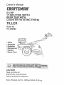
Owner's Manual
®
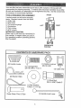
5.5 HP
17 raNCHTUNEWmDTH
REAR TINE WITH
COUNTER ROTATBNG TINE_
TILLE
Model No.
917.293302
Safety
o Assembly
o Operation
o Maintenance
o EspaSol
o Repair Parts
CAUTION:
Read and follow all
Safety Rules and Instructions
before operating this equipment
Sears, Roebuck and Co., Hoffman Estates, tL 60179

Warranty ................................................... 2
Safety Rules ............................................. 2
Product Specifications .......................... 4
Assembly ................................................ 5
Operation ......................................... 3 & 8
Maintenance ......................................... t3
Service and Adjustments ...................... 15
Storage .......................................... 3 & 19
Troubleshooting .................................... 20
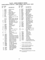
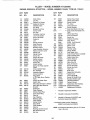
Illustrated Parts List .............................. 42
Parts Ordering ........................ Back Cover
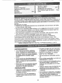
LIMITED TWO YEAR WARRANTY ON CRAFTSMAN TILLER
For two (2) years from date of purchase, when this Craftsman Tiller is maintained, lubri-
cated, and tuned up according to the operating and maintenance instructions in the
owner's manual, Sears will repair free of charge any defect in material or workmanship.
This Warranty does not cover:
° Expendable items which become worn during normal use, such as tines, spark plugs,
air cleaners and belts.
Repairs necessary because of operator abuse or negligence, including bent crank-
shafts and the failure to maintain the equipment according to the instructions con-
tained in the owner's manual.
• If this Craftsman Tiller is used for commercial or rental purposes, this Warranty
applies for only thirty (30) days from the date of purchase.
Warranty service is available by returning the Craftsman power mower to the nearest
Sears service center/department in the United States. This warranty applies oniy while
this product is in use in the United States°
This Warranty gives you specific legal rights, and you may also have other rights which
vary from state to state.
SEARS, ROEBUCK AND CO., D/817WA, HOFFMAN ESTATES, IL 60179
TRAINIING
Read the Owner's Manual carefully. Be
thoroughly familiar with the controls and
the proper use of the equipmenL Know
how to stop the unit and disengage the
controls quickly°
° Never allow children to operate the
equipment. Never allow adults to oper-
ate the equipment without proper
instruction.
• Keep the area of operation clear of all
persons, particularly small children, and
pets.
PREPARATION
o Thoroughly inspect the area where the
equipment is to be used and remove all
foreign objects.
o Disengage all clutches and shift into
neutral before starting the engine (mo -
tor)_
• Do not operate the equipment without
wearing adequate outer garments. Wear
footwear that will improve footing on
slippery surfaces.
° Handle fuel with care; it is highly flarn-
rnable.
° Use an approved fuel container.
° Never add fuel to a running engine or
hot engine.
o Fill fuel tank outdoors with extreme care.
Never fill fuel tank indoors.
° Replace gasoline cap securely and
clean up spilled fuel before restarting_
o Use extension cords and receptacles as
specified by the manufacturer for all
units with electric drive motors or electric
starting motors.
o Never attempt to make any adjustments
while the engine (motor) is running
(except where specifically recommend-
ed by manufacturer).

OPERATION
• Do not put hands or feet near or under
rotating parts.
o Exercise extreme caution when operat-
ing on or crossing gravel drives, walks,
or roads. Stay alert for hidden hazards
or traffic. Do not carry passengers.
o After striking a foreign object, stop the
engine (motor), remove the wire from
the spark plug, thoroughly inspect the
tiller for any damage, and repair the
damage before restarting and operating
the tiller.
o Exercise caution to avoid slipping or
falling°
° tf the unit should start to vibrate abnor-
mally, stop the engine (motor) and check
immediately for the cause. Vibration is
generally a warning of trouble.
o Stop the engine (motor) when leaving
the operating position.
o Take all possible precautions when leav-
ing the machine unattended. Disengage
the tines, shift into neutral, and stop the
engine.
o Before cleaning, repairing, or inspecting,
shut off the engine and make certain all
moving parts have stopped, Disconnect
the spark plug wire, and keep the wire
away from the plug to prevent accidental
starting. Disconnect the cord on electric
motors°
o Do not run the engine indoors; exhaust
fumes are dangerous.
o Never operate the tiller without proper
guards, plates, or other safety protective
devices in place.
° Keep children and pets away.
o Do not overload the machine capacity
by attempting to till too deep at too fast a
rate.
o Never operate the machine at high
speeds on slippery surfaces. Look
behind and use care when backing.
o Never allow bystanders near the unit.
. Use only attachments and accessories
approved by the manufacturer of the
tiller..
o Never operate the tiller without good vis-
ibility or light.
o Be careful when tilling in hard ground.
The tines may catch in the ground and
propel the tiller forward. If this occurs,
let go of the handlebars and do not
restrain the machine°
MAINTENANCE AND STORAGE
° Keep machine, attachments, and
accessories in safe working condition.
• Check shear pins, engine mounting
bolts, and other bolts at frequent inter-
vals for proper tightness to be sure the
equipment is in safe working condition.
. Never store the machine with fuel in the
fuel tank inside a building where ignition
sources are present, such as hot water
and space heaters, clothes dryers, and
the like. Allow the engine to cool before
storing in any enclosure.
• Always refer to the operator's guide
instructions for important details if the
tiller is to be stored for an extended peri-
od.
,_kCAUTION: Always disconnect spark
plug wire and place wire where it cannot
contact spark plug in order to prevent acci-
dental starting when setting up, transport-
ing, adjusting or making repairs.
,_WARNING
The engine exhuast from this product con-
tains chemicals known to the State of
California to cause cancer, birth defectd, or
other reproductive harm°
3

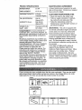
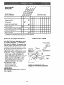
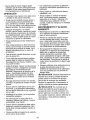
PRODUCT SPECIFICATIONS
HORSEPOWER: 5.5 HP
DISPLACEMEN]_ 13 CU. IN.
GASOLINE CAPACITY: 4 Quarts
Unleaded Regular
OIL (API-SFiSG/SH): SAE 30
(Above 32°F)
(CAPACITY: 20 oz.) SAE 5W-30
(Below 32°F)
SPARK PLUG : Champion RJ19LM
(GAP: .030") OR J 19LM
Congratulations on your purchase of a
Craftsman Tiller: It has been designed, en-
gineered and manufactured to give you the
best possible dependability and perform-
ance.
Should you experience any problems you
cannot easily remedy, please contact your
nearest authorized Sears Service
Center/Department. We have competent,
well-trained technicians and the proper
tools to service or repair this unit.
Please read and retain this manual. The
instructions will enable you to assemble
and maintain your tiller properly. Always
observe the "SAFETY RULES",
Your new tiller has been assembled at the
factory with exception of those parts left
unassembled for shipping purposes, To
ensure safe and proper operation of your
tiller all parts and hardware you assemble
must be tightened securel Y. Use the cor-
rect tools as necessary to insure proper
tightness.
MAINTENANCE AGREEMENT
A Sears Maintenance Agreement is avail-
able on this product. Contact your nearest
Sears store for details.
CUSTOMER RESPONSIBILITIES
o Read and observe the safety rules.
° Follow a regular schedule in maintain-
ing, caring for and using your tiller:
o Follow the instructions under' the
"Maintenance" and "Storage" sections of
this Owner's Manual.
_kWARNING: This unit is equipped with
an internal combustion engine and should
not be used on or near any unimproved
forest-covered, brush-covered or grass
covered land unless the engine's exhaust
system is equipped with a spark attester
meeting applicable local or state laws (if
any). If a spark arrester is used, it should
be maintained in effective working order by
the operator.
In the state of California the above is
required by law (Section 4442 of the
California Public Resources Code). Other
states may have similar laws. Federal
laws apply on federal lands° See your
Sears Authorized Service Center for spark
arrester. Refer to the Repair Parts section
of this manual for part number,
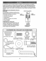
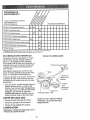
"These accessories were available when the tiller was purchased. "[hey are also avail-
able at most Sears Retail outlets and Service Centers. Most Sears Stores can order
repair parts for you when you provide the model number of your tiller.
ENGINE
MUFFLER AIR FILTF_R GAf_ CAN ENGINE OIL I STABILIZER
TILLER PERFORMANCE
]SLLER MAINTENANCE
BELT ........... ,,,, ,',,,'TINES ...... SHEAR PIN HAIRPIN CLIP
,i i, ,,, ,,,, ,,i,, ,,,,,,,,,,,,, ,...................
4
?

Your new tiller has been assembled at the factory with exception of those parts left
unassembled for shipping purposes. To ensure safe and proper operation of your tiller
all parts and hardware you assemble must be tightened securely. Use the correct too_s
as necessary to insure proper tightness.
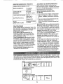
TOOLS REQUIRED FOR ASSEMBLY
A socket wrench set will make assembly
easier. Standard wrench sizes are listed.
(I) Utility knife
(l) Wire cutter
(1) Tire pressure gauge
(1) Screwdriver
(t) Pair of pliers
(1) 9/I6" wrench
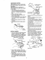
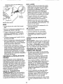
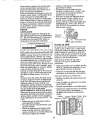
OPERATOR'S POSITION
When right or left hand is mentioned in
this manual, it means when you are in
the operating position (standing behind
tiller handles).
LEFT
FRONT
OPERATOR'S
POSITION
RIGHT
(2) Handle Locks
(2) Hairpin Clips
Extra Shear Pins & Clips
(1) Carriage Bolt
3/8-16 UNC x 1 Gr, 5
(I) Flat Washer
13/32 x t x 11 Ga.
©
G
(t) Center Locknut
3/8d 6 UNC
(1) Cable Clip
(1) Pivot Bolt
3/8-t6 UNC Grade 5
(1) Handle Lock Lever

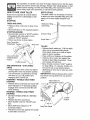
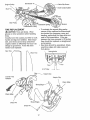
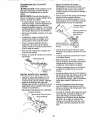
UNPACKING CARTON
_kCAUTION: Be careful of exposed sta-
ples when handling or disposing of carton-
ing material.
IMPORTANT:When unpacking and
assembling tiller, be careful not to stretch
or kink cables.
o While holding handle assembly, cut
cable ties securing handle assembly to
top frame. Let handle assembly rest on
tiller_
• Remove top frame of carton.
o Slowty ease handle assembly up and
place on top of carton.
° Cut down right hand front and right hand
rear corners of carton, lay side carton
wall down.
o Remove packing material from handle
assembly.
o Separate shift rod from handle assem-
bly.
Shift Rod
Assernbly
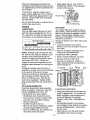
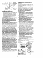
INSTALL HANDLE
° Insert one handle lock (,with teeth facing
outward) in gearcase notch. (Apply
grease on smooth side of handle lock to
aid in keeping lock in place until handle
assembly is lowered into position.)
Viewed from r.h. side of tiller
dandle Assembly
Gearcase Notch
Handle Lock
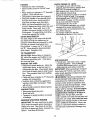
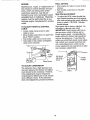
° Grasp handle assembly. Hold in "up"
position. Be sure handle lock remains in
gearcase notch. Slide handle assembly
into position.
• Rotate handle assembly down. Insert
rear carriage bolt first, with head of bolt
on LH. side of tiller and loosely assem-
ble Iocknut.
, Handle AsserfibEy
"UP" Position
"_,. Tighten handle lock
.''_.. ever to hold
Loosen Handle
Lever to Move
o Insert pivot bolt in front part of plate and
tighten.
° Cut down remaining corners of carton
and lay panels flat.
o Lower the handle assembly. Tighten nut
on carriage bolt so handle moves with
some resistance. This will allow for eas-
ier adjustment.
o Place flat washer on threaded end of
handle lock lever.
- Insert handle lock lever through handle
base and gearcase. Screw in handle
lock lever just enough to hold lever in
place.
o insert second handle lock (with teeth
inward) in the slot of the handle base
(just inside of washer),
o Raise handle assembly to highest posi-
tion and securely tighten handle lock
lever by rotating clockwise, Leaving
handle assembly in highest position will
make it easier to connect shift rod.
Handle Lock Flat Washer
Gearcase \ Handle Lock
Slot
Rear Cartridge
Bolt
Pivot Bolt
Handle

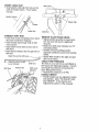
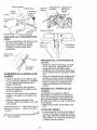
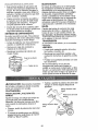
INSERT CABLE CLIP
o Insert plastic cable clip into hole on the
back of handle column. Push cables
into clip.
Handle Column
Cables
Cable Clip
Shift
Shift Rod
CONNECT SHIFT ROD
* Insert end of shift rod farthest from bend
into hole of shift lever indicator°
o Insert hairpin clip through hole of shift
rod to secure.
o Insert other end of shift rod into hole in
shift lever.
° Insert second hairpin clip through hole of
shift rod.
Attach this end to shift lever...._
t,,,,uAttach this End To shift \
Lever Indicator Shift Rod
Shift Rod Hairpin Clip Shift Lever
Indicator
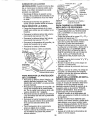
REMOVE TILLER FROM CRATE
,, Adjust handle assemby to lowest posi-
tion. Be sure lock lever is tightened
securely.
o Make sure shift lever indicator is in "N"
(neutral) position,
o Tilt tiller forward by lifting handle°
Separate cardboard cover from leveling
shield.
o Rotate tiller handle to the right and pull
tiller out of carton.
CHECK TIRE PRESSURE
The tires on your unit were overinflated at
the factory for shipping purposes. Correct
and equal tire pressure is important for
best tilling performance,
° Reduce tire pressure to 20 PSL
HANDLE HEIGHT
° Handle height may be adjusted to better
suit operator. (See "TO ADJUST HAN-
DLE HEIGHT" in the Service and
Adjustments section of this manual).

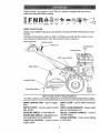
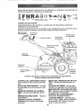
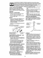
These symbols mayappearon yourTiller or inliteraturesuppliedwith the product.
Learnand understandtheir meaning,
ENGINE ENGINE FA_T SLOW CHOKE
OH OFF
RUN
FUEL O_L _,TOP O
KNOW YOUR TILLER
READ THIS OWNER'S MANUALAND SAFETY RULES BEFORE OPERATING YOUR
TILLER.
Compare the illustrations with your tiller to familiarize yourself with the location of vari-
ous controls and adjustments, Save this manual for future reference.
Drive Control Bar Throttle Control
Lever'
Choke Control
Fuel Shut-Off
valve
Shift Lever Indicator
Depth Stake
Leveling
Outer Side Shield
Recoil
Starter
Handle
MEETS ANSI SAFETY REQUIREMENTS
Our tillers conform to the safety standards of the American National Standards institute,
DRIVE CONTROL BAR - Used to engage
tines.
DEPTH STAKE - Controls depth at which
tiller will dig.
LEVELING SHIELD - Levels tilled soil.
OUTER SIDE SHIELD - Adjustable to pro-
tect small plants from being buried.
THROTTLE CONTROL - Used to control
engine speed.
SHIFT LEVER - Used to shift transmission
gears.
SHIFT LEVER INDICATOR - Shows which
gear the transmission is in.
RECOIL STARTER HANDLE - Used to
start the engine.
CHOKE CONTROL - Used when starting
a cold engine.

The operation of any tiller can result in foreign objects thrown into the eyes,
which can result in severe eye damage° Always wear safety glasses or eye
shields before starting your tiller and while tilling. We recommend a wide
vision safety mask over spectacles or standard safety glasses°
HOW TO USE YOUR TILLER
Know how to operate all controls before
adding fuel and oil or attempting to start
engine°
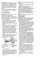
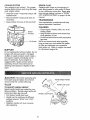
STOPPING
DEPTH STAKE
The depth stake can be raised or lowered
to allow you more versatile tilling and culti-
vating, or to more easily transport your
tiller,
TINES AND DRIVE
, Release drive control bar to stop move-
ment.,
• Move shift lever to "N" (neutral) position°
STOPPING ENGINE
o Move throttle control to "STOP" position.
If equipped with stop switch, move
switch to "STOP" position.
° Never use choke to stop engine.
Drive Control Bar
"ENGAGED" Position Shift Lever
Drive Bar
"DISENGAGED"
Position
Thr&le
TINE OPERATION - WITH WHEEL
DRIVE
• Always release drive control bar before
moving shift lever into another position.
• line movement is achieved by moving
shift lever to ( _ ) til! position and
engaging drive control bar,
FORWARD - WHEELS ONLY/TINES
STOPPED
o Release drive control bar and move shift
lever indicator to "F" (forward) position.
Engage drive control bar and tiller wil!
move forward,
REVERSE - WHEELS ONLY/TINES
STOPPED
° DO NOT STAND DIRECTLY BEHIND
TILLER°
o Release the drive control bar.
o Move throttle control to "SLOW" posi-
tion.
o Move shift lever indicator to "R"
(reverse) position_
o Hold drive control bar against the handle
to start tiller movement.
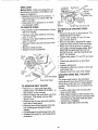
Shallowest Tilling ...._
(Cultivating)
Deepest Tilling
_" Transport Position
Depth Stake ,_
TILLING
° Release depth stake pin. Pull the depth
stake up for increased tilling depth.
Place depth stake pin in hole of depth
stake to lock in position.
o Place shift lever indicator in till position.
• Hold the drive control bar against the
handle to start tilling movement. Tines
and wheels will both turn.
o Move throttle control to "FAST" position
for deep tilling. To cultivate, throttle con-
trol can be set at any desired speed,
depending on how fast or slow you wish
to cultivate.
IMPORTANT: Always release drive control
bar before moving shift lever into another
position.
Depth Stake Pin
Position
Nut "B"
Nut "A"
Outer Side Shield
"Locked"
Position
9

TURNING
o Release the drive control bar.
= Move throttle control to "SLOW" posi-
tion.
= Place shift lever indicator in "F" (forward)
position. Tines will not turn°
o Lift handle to raise tines out of ground.
o Swing the handle in the opposite direc-
tion you wish to turn, being careful to
keep feet and legs away from tines.
° When you have completed your turn-
around, release the drive control bar and
lower handle. Place shift lever in till
position and move throttle control to de-
sired speed_ To begin tilling, hold drive
control bar against the handle.
OUTER SIDE SHIELDS
The back edges of the outer side shields
are slotted so that the shields can be
raised for deep tilling and lowered for shal-
low tilling to protect small plants from
being burJed_ Loosen nut "A" in slot and
nut "B". Move shield to desired position
(both sides). Retighten nuts,
TO TRANSPORT
,_kCAUTION; Before lifting or transport-
ing, allow tiller engine and muffler to cool.
Disconnect spark plug wire. Drain gaso-
line from fuel tank.
AROUND THE YARD
o Release the depth stake pin. Move the
depth stake down to the top hole for
transporting the tiller. Place depth stake
pin in hole of depth stake to lock in posi-
tion. This prevents tines from scuffing
the ground.
o Place shift lever indicator in "F" (forward)
position for transporting.
o Hold the drive control bar against the
handle to start filler movement. Tines
will not turn.
° Move throttle control to desired speed.
AROUND TOWN
° Disconnect spark plug wire_
° Drain fuel tank.
° Transport in upright position to prevent
oil leakage.
BEFORE STARTING ENGINE
IMPORTANT: Be very careful not to allow
dirt to enter the engine when checking or
adding oil or fuel. Use clean oil and fuel
and store in approved, clean, covered con-
tainers. Use clean fill funnels.
CHECK ENGINE OIL LEVEL
° The engine in your unit has been
shipped, from the factory,, already filled
with SAE 30 summer weight oil.
• With engine level, clean area around oil
filler plug and remove plug.
° Engine oil should be to point of overflow-
ing when engine is level. For approxi-
mate capacity see "PRODUCT SPECI-
FICATIONS" on page 4 of this manual.
All oil must meet A.P.I. Service
Classification SF, SG or SH.
• For cold weather operation you should
change oil for: easier starting (See oil
viscosity chart in the Maintenance sec-
tion of this manual).
° To change engine oil, see the
Maintenance section in this manual.
oil
Filler
Oil Level Plug
Oil Drain Plug
ADD GASOLINE
o Fill fuel tank° Use fresh, clean, regular'
unleaded gasoline. (Use of leaded
gasoline will increase carbon and lead
oxide deposits and reduce valve life.
IMPORTANT: When operating in tempera-
tures below 32°F (0°C), use fresh, clean,
winter grade gasoline to help insure good
C_dAweather starting.
RNING: Experience indicates that
alcohol blended fuels (called gasohol or
using ethanol or methanol) can attract
moisture which leads to separation and
formation of acids during storage, Acidic
gas can damage the fuel system of an
engine while in storage. To avoid engine
problems, the fuel system should be
emptied before storage of 30 days or
longer. Drain the gas tank, start the
engine and let it run until the fuel lines and
carburetor are empty. Use fresh fuel next
season. See Storage section of this man-
ual for additional information_ Never use
engine or carburetor cleaner products in
the fuel tank or permanent damage may
occur.
10

,_CAUTION: Fill to within 1/2 inch of top
of fuel tank to prevent spills and to allow
for fuel expansion_ If gasoline is acciden-
tally spilled, move machine away from
area of spill Avoid creating any source of
ignition until gasoline vapors have disap-
peared.
Do not overfill. Wipe off any spilled oil or
fuel. Do not store, spill or use gasoline
near an open flame.
TO START ENGINE
.4{&CAUTION: Keep tine control in "OFF"
position when starting engine°
When starting engine for the first time or if
engine has run out of fuel, it will take extra
pulls of the recoil starter to move fuel from
the tank to the engine.
o Make sure spark plug wire is properly
connected and access cover is com-
pletely closed to create proper seal.
o Move shift lever indicator to "N" (neutral)
position.
• Place throttle control in "FAST" position.
o Turn fuel shut-off valve to "ON" position.
o Push stop switch to "ON" position
o Move choke control to full "CHOKE"
position. Grasp recoil starter handle with
one hand and grasp tiller handle with
other hands Pull rope out slowly until
engine reaches start of compression
cycle (rope will pull slightly harder at this
point).
° Pull recoil starter handle quickly. Do not
let starter handle snap back against
starter. Repeat if necessary.
Choke Contro, _
Switch
Counter- _'-_
Clockwise
Fuel shut-off Valve
If engine fires but does not start, move
choke control to half choke position. Pul!
recoil starter handle until engine starts°
o When engine starts, slowly move choke
control to "RUN" position as engine
warms up.
NOTE: A warm engine requires less chok-
ing to start.
- Move throttle control to desired running
position..
. Allow engine to warm up for a few min-
utes before engaging tines.
NOTE: If at a high altitude (3000 feet) or
in cold temperatures (below 32°F), the car-
buretor fuel mixture may need to be
adjusted for best engine performance.
See "TO ADJUST CARBURETOR" in the
Service and Adjustments section of this
manual.
NOTE; If engine does not start, see trou-
bleshooting points.
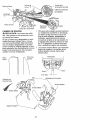
TILLING HINTS
,_CAUTION: Until you are accustomed to
handling your tiller, start actual field use
with throttle in slow position (mid-way
between "FAST" and "IDLE")o
• Tilling is digging into, turning over, and
breaking up packed soil before planting.
Loose, unpacked soil helps root growth.
Best tilling depth is 4" to 6". A tiller will
also clear the soil of unwanted vegeta-
tion. The decomposition of this veg-
etable matter enriches the soil.
Depending on the climate (rainfall and
wind), it may be advisable to till the soil
at the end of the growing season to fur-
ther condition the soil.
o Soil conditions are important for proper
tilling. Tines wil! not readily penetrate
dry, hard soil which may contribute to
excessive bounce and difficult handling
of your tiller. Hard soil should be mois-
tened before tilling; however, extremely
wet soil will "ball-up" or clump during till-
ing. Wait until the soil is less wet in order
to achieve the best results. When tilling
in the fall, remove vines and long grass
to prevent them from wrapping around
the tine shaft and slowing your tilling
operation.
o You will find tilling much easier if you
leave a row untilled between passes.
Then go back between tilled rows. There
are two reasons for doing this° First,
wide turns are much easier to negotiate
than about-faces. Second, the tiller
won't be pulling itself, and you, toward
the row next to it.
o Do not lean on handle. This takes
weight off the wheels and reduces trac-
tion.
1!

Togetthrougha reallytough sectionof
sod orhard ground,apply upward pres-
sure on handle or lower the depth stake.
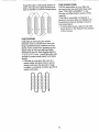
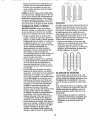
CULTIVATING
Cultivating is destroying the weeds
between rows to prevent them from rob-
bing nourishment and moisture from the
plants. At the same time, breaking up the
upper layer of soil crust will help retain
moisture in the soil. Best digging depth is
1" to 3" (2.5-7.5 cm). Lower the outer side
shields to protect small plants from being
buded,
• Cultivate up and down the rows at a
speed which will al!ow tines to uproot
weeds and leave the ground in rough
condition, promoting no further growth of
weeds and grass,
0 0 010 0
o o 0!o 0
0 00lO 0
0 0 040 O;
TINE SHEAR PiNS
The tine assemblies on your tiller are
secured to the tine shaft with shear pins
(See "TINE REPLACEMENT" in the
Service and Adjustments section of this
manual).
If the tiller is unusually overloaded or
jammed, the shear pins are designed to
break before internal damage occurs to
the transmission.
o if shear pin(s) break, replace only with
those shown in the Repair' Parts section
of this manual.
12

MAINTENANCE
SCHEDULE
FILL IN DATES
AS YOU COMPLETE
REGULAR SERVICE
# ,.
SERVICE DATES
Check Engine Oit Lever _ 6/
Change Engine Oil t_1,2
i .......................
Oil Pivot Points 6/
Inspect Spark Attester/Muffler !_
Inspect Air Screen
Clean or Replace Air Cleaner Cartridge 6,/2
Clean Engine Cylinder Fins
Replace Spark Plug
I - Change more o_'ten when operating under a heavy load or in high ambient temperatures
2 - Service more often when operating in dirty ordusty condilions
GENERAL RECOMMENDATIONS
The warranty on this tiller does not cover
items that have been subjected to opera-
tot abuse or negligence. To receive full
value from the warranty, the operator must
maintain tiller as instructed in this manual.
Some adjustments will need to be made
periodically to properly maintain your tiller.
All adjustments in the Service and
Adjustments section of this manual should
be checked at least once each season.
• Once a year you should replace the
spark plug, clean or replace air filter, and
check tines and belts for wear. A new
spark plug and clean air filter assure
proper air-fuel mixture and help your
engine run better and last longer.
BEFORE EACH USE
• Check engine oil level.
• Checktine operation.
o Check for loose fasteners.
LUBRICATION
Keep unit well lubricated (See "LUBRICA-
TION CHART").
LUBRICATION CHART
* Throttle Control
-%
* Idler Bracket
Wheel Hub
Depth Stake Pin
* Leveling
Shield
Hinges
* SAE 30 OR 5W-30 MOTOR OIL
** REFER TO MAINTENANCE "ENGINE"
SECTION
13

Disconnectsparkplugwire beforeper-
formingany maintenance(exceptcarbure-
tor adjustment)to preventaccidentalstart-
ingof engine.
Preventfires! Keep the engine free of
grass, leaves, spilled oil, or fuel. Remove
fuel from tank before tipping unit for' main-
tenance. Clean muffler area of all grass,
dirt, and debris.
Do not touch hot muffler or cylinder fins as
contact may cause burns.
ENGINE
LUBRICATION
Use only high quality detergent oil rated
with APt service classification SF, SG or
SH_ Select the oil's SAE viscosity grade
according to your expected temperature.
NOTE: Although multi-viscosity oils (5W-
30, 10W-30, etc.) improve starting in cold
weather; these multi-viscosity oils will
result in increased oil consumption when
used above 32°F (0°C). Check your
engine oil level more frequently to avoid
possible engine damage from running low
on oil.
Change the oil after every 50 hours of
operation or at least once a year if the tiller
is not used for 50 hours in one year:
Check the crankcase oil level before start-
ing the engine and after each five (5)
hours of continuous use. Add SAE 30
motor oil or equivalent. Tighten oil filler
plug securely each time you check the oil
level.
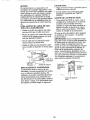
TO CHANGE ENGINE OIL
Determine temperature range expected
before oil change. All oil must meet API
service classification SF, SG or SH.
o Be sure tiller is on level surface.
- Oil will drain more freely when warm.
= Use a funnel to prevent oil spill on tiller,
and catch oil in a suitable container.
Remove drain plug.
• Tip tiller forward to drain oil.
• After oil has drained completely, replace
oil drain plug and tighten securely.
° Remove oil filler plug. Be careful not to
allow dirt to enter the engine.
• Refill engine with oil. See "CHECK
ENGINE OIL LEVEL" in the Operatioq
section of this manual.
OII Drain Plug
Oil Level
Oil Filler Plug
AIR FILTER
Your engine will not run propedy using a
dirty air filter: Clean the foam pre-cleaner
after every 50 hours of operation or every
season. Service paper cartridge every
100 hours of operation or every season,
whichever occurs first°
Service air cleaner more often under dusty
conditions°
o Loosen air cleaner cover screws.
Remove cover and air cleaner assembly
from base°
. Remove air cleaner asssembly from
inside cover and disassemble.
TO SERVICE PRE-CLEANER
= Wash it in liquid detergent and water:
° Squeeze it dry in a clean cloth.
= Saturate it in engine oil. Wrap it in
clean, absorbent cloth and squeeze to
remove excess oil.
Pre-Cleaner Cover Base
fill
;over Screws
"TOSERVICE CARTRIDGE
o Gently tap the flat side of the paper car-
tridge to dislodge dirt. Do not wash the
paper cartridge or use pressurized air,
as this will damage the cartridge.
Replace a dirty, bent, or damaged car-
tridge.
• Re-assernble retainer on pre-cfeaner
and cartridge (screen side of pre-cleaner
toward cartridge pleats). Place assem-
bly into cover.
Insert tabs on cover into slots in base
and tighten cover screws securely°
°
14

COOLING SYSTEM
Your engine is air cooled. For proper
engine performance and long life keep
your engine clean°
o Clean air screen frequentlyusingastiff-
bristledbrush_
• Removeblowerhousingand cleanas
necessary.
° Keepcylinderfins freeof dirt andchaff_
Blower
Housing
Air Screen
MUFFLER
Do not operate tiller without muffler. Do not
tamper with exhaust system. Damaged
mufflers or spark arresters could create a
fire hazard. Inspect periodically and re-
place if necessary° If your engine is
equipped with a spark arrester screen
assembly, remove every 50 hours for
cleaning and inspection_ Replace if dam-
aged°
SPARK PLUG
Replace spark plugs at the beginning of
each tilling season or after every 50 hours
of use, whichever comes first. Spark plug
type and gap setting is shown in "PROD-
UCT SPECIFICATIONS" on page 4 of this
manual,,
TRANSMISSION
Your transmission is sealed and will only
require lubrication if serviced.
CLEANING
o Clean engine, wheels, finish, etc. of all
foreign matter°
o Keep finished surfaces and wheels free
of all gasoline, oil, etco
o Protect painted surfaces with automotive
type wax_
We do not recommend using a garden
hose to clean your unit unless the muffler,
air filter and carburetor are covered to
keep water out° Water in engine can result
in a shortened engine life,
,&CAUTION: Disconnect spark plug wire
from spark plug and place wire where it
cannot come into contact with plug.
TILLER
TO ADJUST HANDLE HEIGHT
Select handle height best suited for your
tiIling conditions. Handle height will be dif-
ferent when tiller digs into soil.
o First loosen handle lock lever.
° Handle can be positioned at different
settings between "HIGH" and "LOW"
positions.
o Retighten handle lock lever securely
after adjusting.
Handle (Low) Position
Handle (High) Position
Handle Lock Lever
15

TIIRE CARE
_CAUTiON: When mounting tires, un-
less beads are seated, overinflation can
cause an explosion.
o Maintain 20 pounds of tire pressure, tf
tire pressures are not equal, tiller will
pull to one side_
o Keep tires free of gasoline or oi! which
can damage rubber:
TO REMOVE WHEEL
o Place blocks under transmission to keep
tiller from tipping.
= Remove outer side shield by removing
nuts "A" and "B".
= Remove inner side shield by removing
nuts "C" and "D",
• Remove hairpin clip and clevis pin from
wheel.
• Remove wheel and tire.
o Repair tire and reassemble.
Clevis
Hairpin
Clip
Nut "B"
Nut "A
Inner Side Shield
Outer Side Shield
TO REMOVE BELT GUARD
° Remove L.H. outer and inner side
shields (See 'q'O REMOVE WHEEL" in
this section of this manual).
° Remove hairpin clip and clevis pin from
left wheel. Pull wheel out from tiller
about 1 inch.
o Remove two (2) cap nuts and washers
frorn side of belt guard.
o Remove hex nut and washer from bot-
tom of belt guard (located behind
wheel).
° Pull belt guard out and away from unit,
° Replace belt guard by reversing above
procedure_ ,
Belt Guard
Hex Nut and
Washer
(Located
BehindTire)
Cap Nut
and
Washer Hairl and Clevis Pin
TO REPLACE GROUND DRIVE
BELT
• Remove belt guard as described it1'%0
REMOVE BELT GUARD".
° Loosen bett guides "A" and "B" and
also remove stud "C"o
° Remove old belt by slipping off engine
pulley first then remove from the pulley.
° Place new belt in groove of transmis-
sion pulley and into engine pulley_ BELT
MUST BE IN GROOVE ON TOP OF
IDLER PULLEY_ NOTE POSITION OF
BELT TO GUIDES.
o Tighten belt guides "A" and "B" and stud
_C t_.
• Check belt adjustment as described
below.
o Replace belt guard.
o Reposition wheel and replace clevis pin
and hairpin clip.
° Replace inner and outer side shields.
GROUND DRIVE BELT ADJUST-
MENT
For proper belt tension, the extension
spring should have about 5/8 inch stretch
when drive control bar is in "ENGAGED"
position. This tension can be attained as
follows:
• Loosen cable ctip screw securing tile
drive control cable.
• Slide cable forward for less tension and
rearward for more tension until about 5/8
inch stretch is obtained while the drive
control bar is engaged.
• Tighten cable clip screw securely.
16

Engine Pulley
Stud "C',_,
Belt Guide "A"
Clip Screw
Drive Control Cable
Idler Pulley
Extension Spring
Transmission Pulley
Fension
TINE REPLACEMENT °
,_kCAUTION: Tines are sharp. Wear
gloves or other protection when handling
tines.
A badly worn tine causes your tiller to work
harder and dig more shallow. Most impor-
tant, worn tines cannot chop and shred
organic matter as effectively nor bury it as
deeply as good tines. A tine this worn °
needs to be replaced.
New Tine
Tine
To maintain the superb tilling perfor-
mance of this machine the tines should
be checked for sharpness, wear, and
bending, particularly the tines which are
next to the transmission. If the gap
between the tines exceeds 3-1/2 inches
they should be replaced or straightened
as necessary.
New tines should be assembled. Sharp-
ened tine edges will rotate rearward
from above.
transmission_
3-1/2" Max
Counter Tine
Rotation
Hairpin Clip
Sharp Edge
Sharp Edge
Shear Pin
Shear Pin
17

ENGBNE
Maintenance, repair, or replacement of
the emission control devices and sys-
tems, which are being done at the
customers expense, may be per-
formed by any non-road engine repair
establishment or individual. Warranty
repairs must be performed by an au-
thorized engine manufacturer's service
outlet.
TO ADJUST THROTTLE CONTROL
CABLE
• Loosen cable clamp screw to allow
cable to move.
= Move throttle control lever on upper han-
dle to "FAST" position.
° Pull throttle cable out to end of travel
° Hold cable in this position and tighten
clamp screw securely.
FINAL SETTING
° Start engine and allow to warm for five
minutes.
o With throttle control lever in "SLOW"
position°
IDLE RPM ADJUSTMENT
= To adjust idle RPM, rotate throttle link-
age counterclockwise and hold against
stop while adjusting idle speed adjusting
screw to obtain t750 RPM. Release
throttle linkage.
High speed stop is factory adjusted. Do
not adjust or damage may result.
IMPORTANT: Never tamper with the en-
gine governor, which is factory set for
proper engine speed, overspeeding the
engine above the factory high speed set-
ting can be dangerous. If you think the
engine-governed high speed needs adjust-
ing, contact your nearest authorized ser-
vice center/department, which has the
proper equipment and experience to make
any necessary adjustments.
Cable
Clamp Screw
TO ADJUST CARBURETOR
The carburetor has a high speed jet and
has been preset at the factory and adjust-
ment should not be necessary. However,
minor adjustments may be required to
compensate for differences in fuel, temper_
ature, altitude or load. tf the carburetor
does need adjustment, proceed as follows.
Idle Speed
Adjustin!
Screw
Valve
Linkage
18

Immediatelyprepareyour tillerfor storage
at theend of theseasonor if the unit will
notbe usedfor 30daysor more°
_kCAUTION: Never store the tiller with
gasoline in the tank inside a building
where fumes may reach an open flame or
spark. Allow the engine to cool before
storing in any enclosure°
TILLER
o Clean entire tiller (See "CLEANING" in
the Maintenance section of this manual),,
o Inspect and replace belts, if necessary
(See belt replacement instructions in the
Service and Adjustments section of this
manual).
° Lubricate as shown in the Maintenance
section of this manual,
o Be sure that all nuts, bolts and screws
are securely fastened, Inspect moving
parts for damage, breakage and wear.
Replace if necessary.
o Touch up all rusted or chipped paint sur-
faces; sand lightly before painting.
ENGINE
FUEL SYSTEM
IMPORTANT: It is important to prevent
gum deposits from forming in essential fuel
system parts such as the carburetor, fuel
filter, fuel hose, or tank during storage.
also, experience indicates that alcohol
btended fuels (called gasohol or using
ethanol or methanol) can attract moisture
which leads to separation and formation of
acids during storage. Acidic gas can dam-
age the fuel system of an engine while in
storage.
o Drain the fuel tank.
= Start the engine and let it run until the
fuel lines and carburetor are empty.
o Never use engine or carburetor cleaner
products in the fuel tank or permanent
damage may occur.
o Use fresh fuel next season.
NOTE: Fuel stabilizer is an acceptable
alternative in minimizing the formation of
fue! gum deposits during storage. Add sta-
bilizer to gasoline in fuel tank or storage
container, Always follow the mix ratio
found on stabilizer container. Run engine
at least I0 minutes after adding stabilizer
to allow the stabilizer to reach the carbure-
tor, Do net drain the gas tank and carbu-
retor if using fuel stabilizer.
ENGINE OIL
Drain oil (with engine warm) and replace
with clean oil. (See "ENGINE" in the
Maintenance section of this manual),
CYLINDER(S)
• Remove spark plug.
o Pour t ounce (29 ml) of oil through
spark plug hole into cylinder.
• Pull starter handle slowly several times
to distribute oil.
• Replace with new spark plug.
OTHER
o Do not store gasoline from one season
to another,
o Replace your gasoline can if your can
starts to rust. Rust and/or dirt in your
gasoline will cause problems.
• If possible, store your unit indoors and
cover it to give protection from dust and
dirt.
o Cover your unit with a suitable protective
cover that does not retain moisture° Do
not use plastic° Plastic cannot breathe
which allows condensation to form and
will cause your unit to rusL
IMPORTANT: Never cover tiller while
engine and exhaust areas are still warm.
19

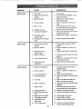
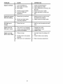
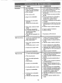
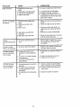
PROBLEM
Will not start
Hard to start
Loss of power
CAUSE
1o Out of fuel.
2. Engine riot"CHOKED"
properly°
3. Engine flooded°
4 Dirty air cleaner
5. Water in fuel
6. Clogged fuel tank.
7. Loose spark plug wire
8_ Bad spark plug or
improper gap
9_ Carburetor out of adjust-
merit.
1. Throttle control not set
properly.
2. Dirty air cleaner:
3. Bad spark plug or
improper gap.
4. Stale or dirty fuel
5. Loose spark plug wire
6_ Carburetor out of.
adjustment,
1. Engine is ovedoadedo
2. Dirty air cleaner
3. Low oil level/dirty oil.
4. Faulty spark plug.
5. Oil in fuel
6. Stale ordirtyfueL
7. Water in fueL
8. Clogged fuel tank.
9. Spark plug wire loose,
wire.
10. Dirty engine air screen.
11. Dirtylclogged muffler.
12. Carburetor out of
adjustment.
13. Poor compression.
2O
CORRECTION
1 Fill fuel tank.
2. See "TO START ENGINE" inthe
Operation section.
3. Wait several minutes before
attempting to start.
4 Clean or replace air cleaner car
tridge
5. Drain fuel tank and carburetor,
and refill tank with fresh gasoline.
6. Remove fuel tank and clean°
7. Make sure spark plug wire is seat
ed properly on plug.
8 Replace spark plug or adjust gap°
9. Make necessary adjustments_
1. Place throttle control in "FAST"
position.
2 Clean or replace air cleaner car
tddgeo
3. Replace spark plug or adjust gap
4 Drain fuel tank and refill with fresh
gasoline.
5. Make sure spark plug wire is seat
ed properly on plug
6. Make necessary adjustments
2.
4.
5.
6.
7.
8.
9.
Set depth stake and wheels for
shallower tilling,
Clean or replace air cleaner car
tridge.
Check oil level/change oil.
Clean and regap or change spark
plug.
Drain and clean fuel tank and
refill, and clean carburetor°
Drain fuel tank and refill with fresh
gasoline,
Drain fuel tank and carburetor,
and refill tank with fresh gasoline.
Remove fuel tank and clean.
Connect and tighten spark plug
t0. Clean engine air screen.
11. Clean/replace muffler.
12. Make necessary adjustments.
13o Contact an authorized Sears
Service CentedDepartment.
Page is loading ...
Page is loading ...
Page is loading ...
Page is loading ...
Page is loading ...
Page is loading ...
Page is loading ...
Page is loading ...
Page is loading ...
Page is loading ...
Page is loading ...
Page is loading ...
Page is loading ...
Page is loading ...
Page is loading ...
Page is loading ...
Page is loading ...
Page is loading ...
Page is loading ...
Page is loading ...
Page is loading ...
Page is loading ...
Page is loading ...
Page is loading ...
Page is loading ...
Page is loading ...
Page is loading ...
Page is loading ...
Page is loading ...
Page is loading ...
Page is loading ...
Page is loading ...
Page is loading ...
Page is loading ...
Page is loading ...
Page is loading ...
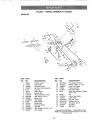
-
 1
1
-
 2
2
-
 3
3
-
 4
4
-
 5
5
-
 6
6
-
 7
7
-
 8
8
-
 9
9
-
 10
10
-
 11
11
-
 12
12
-
 13
13
-
 14
14
-
 15
15
-
 16
16
-
 17
17
-
 18
18
-
 19
19
-
 20
20
-
 21
21
-
 22
22
-
 23
23
-
 24
24
-
 25
25
-
 26
26
-
 27
27
-
 28
28
-
 29
29
-
 30
30
-
 31
31
-
 32
32
-
 33
33
-
 34
34
-
 35
35
-
 36
36
-
 37
37
-
 38
38
-
 39
39
-
 40
40
-
 41
41
-
 42
42
-
 43
43
-
 44
44
-
 45
45
-
 46
46
-
 47
47
-
 48
48
-
 49
49
-
 50
50
-
 51
51
-
 52
52
-
 53
53
-
 54
54
-
 55
55
-
 56
56


Craftsman 917293302 Owner's manual
- Category
- Mini tillers
- Type
- Owner's manual
Ask a question and I''ll find the answer in the document
Finding information in a document is now easier with AI
in other languages
Related papers
-
Craftsman 917299062 Owner's manual
-
-
-
-
-
-
-
-
-
Other documents
-
 Poulan Pro PPCRT14 Owner's manual
-
 Poulan Pro PPCRT17 Owner's manual
-
 Poulan Pro PPCRT14 Owner's manual
-
Jonsered J208D17 User manual
-
 Poulan Pro PPCRT17 Owner's manual
-
 Poulan Pro PPCRT14 Owner's manual
-
Ariens 90102800 Owner's manual
-
Yard Machines 450 User manual
-
MTD 21A-240P052 Owner's manual
-
Black & Decker TL10 User manual


