
GENERAL HAZARD WARNING: Failure to comply
with the precautions and instructions provided with this
heater, can result in death, serious bodily injury and
electrical shock.
Only persons who can understand and follow the in-
structions should use or service this heater.
If you need assistance or heater information such as an in-
structions manual, labels, etc. Contact the manufacturer.
IMPORTANT: Read and understand this manual before
assembling, starting or servicing heater. Improper use
of heater can cause serious injury. Keep this manual for
future reference.
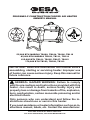
PROPANE/LP CONSTRUCTION FORCED AIR HEATER
OWNER’S MANUAL
55,000 BTU MODELS TB100, TB104, TB106, TB110
85,000 BTU MODELS TB102, TB111, TB114
125,000 BTU TB101, TB105, TB107, TB112
170,000 BTU TB103, TB108, TB113
Save this manual for future reference.
For more information, visit www.desatech.com

www.desatech.com
119143-01A2
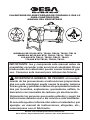
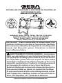
SAFETy INFORMATION
WARNING: This product
chemicals known to the State
of California to cause cancer or
birth defects or other reproduc-
tive harm.
WARNING: Fire, burn, inhala-
solid combustibles, such as build-
ing materials, paper or cardboard,
a safe distance away from the
heater as recommended by the
instructions. Never use the heater
in spaces which do or may contain
volatile or airborne combustibles
or products such as gasoline, sol-
vents, paint thinner, dust particles
or unknown chemicals.
WARNING: Not for home or
recreational vehicle use.
The heater is designed and approved for
use as a construction heater under ANSI
Z83.7•CGA 2.14-2000 Construction Heater.
The purpose of construction heaters is to
provide temporary heating of buildings under
construction, alteration or repair. Properly
used, the heater provides safe economical
heating. Products of combustion are vented
into the area being heated.
We cannot foresee every use which may be
made of our heaters. Check with your local
about heater use.
Other standards govern the use of fuel gases and
heat producing products for specic uses. Your
local authorities can advise you about these.
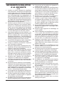
Some people are
more affected by carbon monoxide than oth-
ers. Early signs of carbon monoxide poisoning
resemble the flu, with headaches, dizziness
and/or nausea. If you have these signs, the
heater may not be working properly. Get fresh
air at once! Have heater serviced.
Propane/LP gas is odorless.
An odor-making agent is added to propane/LP
gas. The odor helps you detect a propane/LP
gas leak. However, the odor added to pro-
pane/LP gas can fade. Propane/LP gas may
be present even though no odor exists.
Make certain you read and understand all
warnings. Keep this manual for reference. It
is your guide to safe and proper operation of
this heater.
1. Install and use heater with care. Follow
all local ordinances and codes. In the
absence of local ordinances and codes,
refer to the Standard for Storage and
Handling of Liqueed Petroleum Gas,
ANSI/NFPA 58 and the Natural Gas and
Propane Installation Code CSA B149.1.
This instructs on the safe storage and
handling of propane gases.
2. Use only the electrical voltage and fre-
quency specied on model plate. The
electrical connections and grounding of
the heater shall follow the National Electric
Code, ANSI/NFPA 70 or the Canadian
Electric Code, Part 1.
3. Electrical grounding instructions - This
appliance is equipped with a three-prong
(grounding) plug for your protection against
shock hazard and should be plugged di-
rectly into a properly grounded three-prong
receptacle or extension cord.
4. This product has been approved for use in
the Commonwealth of Massachusetts.
5. For indoor use only. Provide adequate
ventilation.
6. Keep heater away from strong drafts,
wind, water spray, rain or dripping water.
TABLE OF CONTENTS
Safety Information ............................................... 2
Product Identication ........................................... 3
Unpacking............................................................ 4
Assembly ............................................................. 4
Theory of Operation............................................. 4
Propane Supply ................................................... 5
Ventilation ............................................................ 5
Installation ........................................................... 5
Operation ............................................................. 6
Storage ................................................................ 7
Maintenance ........................................................ 7
Service Procedures ............................................. 8
Specications ...................................................... 9
Wiring Diagrams ................................................ 10
Replacement Parts .............................................11
Technical Service................................................11
Service Publications ...........................................11
Accessories ........................................................11
Illustrated Parts Breakdown and Parts List........ 12
Warranty and Repair Service ............................ 18

www.desatech.com
119143-01A 3
7. Use only in well-vented areas. Before using
heater, provide at least a three-square-
foot opening of fresh, outside air for each
100,000 Btu/Hr (105,500 k/j) of rating.
8. Do not use heater outdoors or in occupied
dwellings.
9. Do not use heater in living or sleeping
quarters.
10. Keep appliance area clear and free from
combustible materials, gasoline, paint
thinner and other flammable vapors and
liquids. Dust is combustible. Do not use
heater in areas with high dust content.
11. If this heater is equipped with a thermo-
stat. Heater may start at anytime.
12. Check heater for damage before each
use. Do not use a damaged heater.
13. Use only propane/LP gas set up for vapor
withdrawal.
14.
Keep propane tank(s) below 100° F (38° C).
15. Do not use heater in a basement or below
ground level. Propane/LP gas is heavier
than air. If a leak occurs, propane/LP gas
will sink to the lowest possible level.
16. Use only the hose and factory regulator
provided with the heater.
17. Check hose before each use of heater. If
highly worn or cut, replace with hose speci-
ed by manufacturer before using heater.
18. Do not alter heater. Keep heater in its
original state.
19. Do not use heater if altered.
20. Keep heater at least 6 feet (1.8 m) from
propane/LP tank(s). Do not point heater at
propane/LP tank(s) within 20 feet (6.1 m).
21. Minimum heater clearances from com-
bustibles: Outlet: 8 Ft. (2.4 m), Sides: 2
Ft. (0.6 m), Top: 6 Ft. (1.8 m), Rear: 2 Ft.
(0.6 m).
22. Locate heater on stable and level surface
if heater is hot or running.
23. Keep children and animals away from
heater.
24. Turn off propane/LP supply and unplug
heater when not in use.
25. Never block air inlet (rear) or hot air outlet
(front) of heater.
26. Never move, handle or service a hot,
operating or plugged in heater.
SAFETy INFORMATION
Continued
27. Never attach duct work to front or rear of
heater.
28. Use only original replacement parts. This
heater must use design-specic parts.
Do not substitute or use generic parts.
Improper replacement parts could cause
serious or fatal injuries.
29. Do not use this product without leg and
foot assembly.
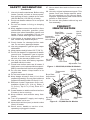
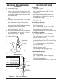
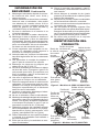
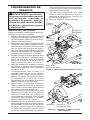
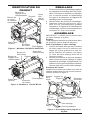
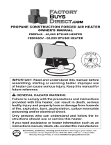
PRODUCT
IDENTIFICATION
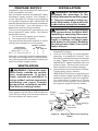
Figure 1 - 55/85/125,000 Btu/Hr Models
Cord Cleat
Adjustable Foot
Burn Rate
Adjustment
Knob
Handle
Hot Air
Outlet
(Front)
Air Inlet
(Rear)
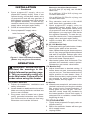
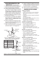
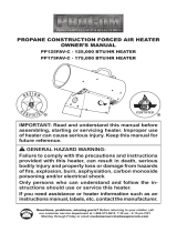
Figure 2 - 170,000 Btu/Hr Models
Cord Cleat
Adjustable
Foot
Burn Rate
Adjustment
Knob
Handle
Hot Air Outlet
(Front)
Air Inlet
(Rear)
Automatic
Gas Control
Valve Button
Thermostat
Knob

www.desatech.com
119143-01A4
Air For
Combustion
Air For
Heating
UNPACkINg
1. Remove all packing items applied to
heater for shipment. Keep plastic cover
cap (attached to heater inlet connector and
hose/regulator assembly) for storage.
2. Remove all items from carton.
3. Check all items for shipping damage. If
heater is damaged, promptly inform dealer
where you bought heater.
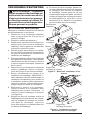
ASSEMBLy
IMPORTANT: Do not use this product without
leg and foot assembly.
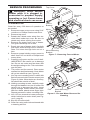
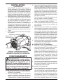
Handle
Attach handle to control box with 2 screws
(long) as shown in Figure 3.
1. Insert leg extensions into outlet end cap
until small hole lines up with larger hole,
visible from inside of outlet end cap (see
Figure 3). Fasten leg extensions with
provided screws (short).
2. Insert plastic foot ends into each leg ex-
tension and set heater to desired angle.
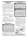
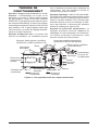
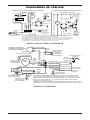
Cool
Air In
(Back)
Motor
Hose/
Regulator
Assembly
Spark Ignitor
Combustion
Chamber
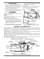
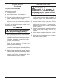
Figure 4 - Cross Section Operational View
Fan
Clean
Heated
Air Out
(Front)
THEORy OF OPERATION
The Fuel System: The hose/regulator assembly attaches to the propane gas supply. For
55/85/125 models, the propane gas moves through the automatic control valve, burn rate
adjustment valve and out the injector. For 170 models, the propane gas moves through the
solenoid valve, burn rate adjustment valve and out the injector.
The Air System: The motor turns the fan. The fan pushes air into and around the combustion
chamber. This air is heated and provides a stream of clean, hot air.
The Ignition System: For 55/85/125 models the high voltage ignitor sends voltage to the spark
ignitor. For 170 models direct spark ignitor sends voltage to the spark ignitor. The spark ignitor
ignites the fuel and air mixture.
The Safety Control System: This system causes the heater to shut down if the flame goes
out. The motor will continue to run, but no heat is produced.
Figure 3 - Handle and Foot Assembly
Solenoid Valve
(170 models only)
Power
Cord
Injector
Thermal
Limit Switch
Small post screws on plastic foot will snap
into holes in leg extensions.
Cord Cleats
Install cord cleats on side of end caps as shown
in Figure 3 with screws provided (short).
Outlet
End Cap
Handle
Leg Extension
Plastic Foot
Small
Post
High Voltage Ignitor (55/85/125
Models) or DSI (170 Models)
Leg Extension
Fastening
Screw (short)
Automatic Control Valve
(55/85/125 models only)
Cord
Cleat
Long screws
Short
Screw

www.desatech.com
119143-01A 5
PROPANE SUPPLy
Propane/LP gas and propane/LP tank(s) are
to be furnished by the user.
Use this heater only with a propane/LP vapor
withdrawal supply system. See Chapter 5
of the Standard for Storage and Handling
of Liqueed Petroleum Gas, ANSI/NFPA 58
and the Natural Gas and Propane Installation
Code CSA B149.1. Your local library or re
department will have these booklets.
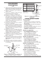
The amount of propane/LP gas ready for use
from propane/LP tanks varies. Two factors
decide this amount:
1. The amount of propane gas in tank(s)
2. The temperature of tank(s)
The chart below shows the number of 100 lb
(45 kg) tanks needed to run this heater.
Number of tanks
Temperature Models
above 20° F (-7° C) 1 1 2
20° F (-7° C) to -0 (-18° C)
1 2 3
Less gas is vaporized at lower temperatures.
You may need a larger tank in colder weather.
Your local propane/LP gas dealer will help you
select the proper supply system.
VENTILATION
WARNING: Follow the mini-
mum fresh, outside air ventila-
fresh, outside air ventilation is
poisoning can occur. Provide
proper fresh, outside air ventila-
tion before running heater.
Provide a fresh air opening of at least
three square feet for each 100,000 Btu/Hr
(105,500 k/j) rating. Provide extra fresh air
if more heaters are being used.
INSTALLATION
WARNING: Review and un-
derstand the warnings in the
Safety Information section, page
2. They are needed to safely op-
erate this heater. Follow all local
codes when using this heater.
WARNING: Test all gas piping
and connections for leaks after
installing or servicing. Never use
and water to all joints. Bubbles
forming show a leak. Correct all
leaks at once.
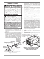
1. Provide propane/LP supply system (see
Propane/LP Supply).
2. Connect POL tting on hose/regulator
assembly to propane/LP tank(s). Turn
POL tting counterclockwise into threads
on tank. Tighten rmly using a wrench.
IMPORTANT: Tighten regulator with vent
pointing down. Pointing vent down pro-
tects regulator from weather damage.
3. Connect hose to inlet connector of heater.
Tighten rmly using a wrench.
IMPORTANT: Extra hose or piping may be
used if needed. Install extra hose or piping
between propane/LP tank and regulator.
You must ensure a minimum of 25 psig
at the inlet of the regulator. You must use
the regulator supplied with the heater.
Propane
Tank
Hose
Regulator
Vent (pointing
down)
Fuel Gas
Connector
Supply
Valve
Figure 5 - Regulator With Vent Pointing
Down
To
Heater
Inlet
Connector
POL Fitting

www.desatech.com
119143-01A6
Up to 50 feet (15 m) long, use 18 AWG
rated cord.
51 to 100 feet (15.5 to 30.5 m) long, use
16 AWG rated cord.
101 to 200 feet (30.78 to 61 m) long, use
14 AWG rated cord.
4. Plug extension cord into a 120 volt/60
hertz, three-hole, grounded outlet.
5. Open propane/LP supply valve on
propane/LP tank(s) slowly. Note: If not
opened slowly, excess-flow check valve
on propane/LP tank will stop gas flow. If
this happens, you may hear a click inside
the regulator assembly. To reset the ex-
cess flow check valve, close propane/LP
supply valve and open again slowly.
6. Adjust variable Btu control knob fully
clockwise to LO.
55, 85, 125 Models Only
7. Press and hold in gas valve button. Heater
should ignite within a few seconds.
Note: If heater fails to ignite, hose may have
air in it. If so, keep gas valve button pressed
and wait 20 seconds. Release gas valve
button and wait 20 seconds for unburned
fuel to exit heater. Repeat step 6.
8. After heater ignites, wait 30 seconds. This
activates the automatic control system.
Release the gas control valve button.
9. Adjust thermostat to desired setting. If
heater does not start, thermostat setting
may be too low. Turn thermostat knob to
higher position to start heater. Note: If
heater does not start, unplug heater. Wait
ten seconds for safety control to reset,
plug in heater, then try again.
All Models
10. When burner remains lit, set heater to the
desired heat level by turning the variable
Btu control knob counterclockwise. If
burner goes out, turn off gas. Turn vari-
able Btu control knob fully clockwise to
the lowest position. Check fuel supply. If
adequate fuel is available, restart heater
beginning at step 1.
TO STOP HEATER
1. Tightly close propane/LP supply valve on
propane tank(s).
2. Wait a few seconds. Heater will burn gas
left in supply hoses.
3. Unplug heater.
OPERATION
WARNING: Review and un-
derstand the warnings in the
Safety Information section, page
2. They are needed to safely op-
erate this heater. Follow all local
codes when using this heater.
TO START HEATER
1. Follow all installation, ventilation and
safety information.
2. Locate heater on stable and level surface.
Make sure strong drafts do not blow into
front or rear of heater.
3. Plug power cord of heater into a three-
prong, grounded extension cord. Exten-
sion cord must be at least six feet long.
Extension cord must be UL listed.
4. Open propane/LP supply valve on
propane/LP tank(s) slowly. Note: If not
opened slowly, excess-flow check valve
on propane/LP tank will stop gas flow. If
this happens, you may hear a click inside
the regulator assembly. To reset the ex-
cess flow check valve, close propane/LP
supply valve and open again slowly.
5. Check all connections for leaks.
6. Close propane/LP supply valve.
INSTALLATION
Continued
Figure 6 - Hose and Inlet Connector
(Heater may vary from illustration)
Hose
Inlet Connector
Gas Valve
Button

www.desatech.com
119143-01A 7
TO RESTART HEATER
If safety control stops gas flow to heater, motor
will continue to run.
1. Unplug heater.
2. Wait ten seconds. Plug heater in.
If heater does not restart
A. Check supply valves (on propane/LP
tank). Make sure they are open.
B. Check fuel level in propane/LP tank(s). If
fuel level is too low, contact local propane/
LP gas company.
If heater still does not restart, contact your
local service center.
STORAgE
CAUTION: Disconnect heater
from propane supply tank(s).
1. Store propane/LP tank(s) in safe manner.
See chapter 5 of Standard for Storage and
Handling of Liqueed Petroleum Gases,
ANSI/NFPA 58 and the Natural Gas and
Propane Installation Code CSA B149.1.
Follow all local codes.
2. Place plastic cover caps over brass t-
tings on inlet connector of heater and
hose/regulator assembly.
3. Store in dry, clean and safe place. Do
not store hose/regulator assembly inside
heater combustion chamber.
4. When taking heater out of storage, always
check inside of heater. Insects and small
animals may place foreign objects in
heater. Keep inside of heater free from
combustible and foreign objects.
OPERATION
Continued
MAINTENANCE
WARNING: Never service
heater while it is plugged in,
connected to propane supply,
operating or hot. Severe burns
and electrical shock can occur.
1. Keep heater clean. Clean heater annually
or as needed to remove dust and debris. If
heater is dirty or dusty, clean heater with
a damp cloth.
2. Inspect heater before each use. Check
connections for leaks. Apply mixture of
liquid soap and water to connections.
Bubbles forming show a leak. Correct all
leaks at once.
3. Inspect hose/regulator assembly before
each use. If hose is highly worn or cut,
replace.
4. Have heater inspected yearly by a quali-
ed service agency.
5. Keep inside of heater free from combus-
tible and foreign objects.

www.desatech.com
119143-01A8
Figure 8 - Fan and Motor Reversed for
Cleaning
Fan
Terminal
Block
Figure 7 - Removing Fan and Motor
Top Cover
SERVICE PROCEDURES
WARNING: Never service
heater while it is plugged in,
connected to propane supply,
operating or hot. Severe burns
and electrical shock can occur.
CLEANING FAN
Clean fan every 500 hours of operation or
as needed.
1. Remove screws on top cover using 5/16"
nut-driver or Phillips head screw driver.
2. Remove top cover.
3. Detach the 2 black motor wires from ter-
minal block under top cover. Be sure to
detach only wires coming from motor.
4. Remove fan guard from rear of heater.
Fan guard will snap out of shell.
5. Reach into rear of heater shell. Carefully
pull motor wires through hole in bracket.
Note: Pull wires through hole one at a
time.
6. Remove screws holding motor mount to
shell. Use 5/16" nut driver or Phillips head
screw driver.
7. Carefully pull motor and fan out of shell.
IMPORTANT: Be careful not to damage
fan. Do not set motor and fan down with
the weight resting on fan. This could dam-
age fan pitch.
8. Turn motor and fan around. Place motor
and fan into shell backwards. Note: Motor
will go into shell rst (see Figure 8).
9. Line up rear mounting holes in shell with
rst hole on each side of motor mount (see
Figure 8). Note: When holes are lined up,
fan should be outside of shell.
10. Holding mounting screws, carefully reach
through fan blades into rear of heater. Be
careful not to damage fan pitch. Insert
screw through motor mount and shell.
With free hand, attach screw nger tight.
Repeat process for other mounting hole.
11. Use 1/8" hex wrench to loosen setscrew
which holds fan to motor shaft (see Fig-
ure 9, page 9).
12. Slip fan off motor shaft.
13. Clean fan using soft cloth moistened with
a cleaning solvent.
Motor
Motor Mounting
Bracket
Motor Mounting
Bracket
Hole in
Bracket

www.desatech.com
119143-01A 9
A
Fan
Hub
Setscrew
Motor
Figure 10 - Fan Cross Section
SERVICE PROCEDURES
Continued
14. Dry fan thoroughly.
15. Replace fan on motor shaft. Place set-
screw on flat of shaft. See chart in Figure
10 for distance of fan hub from end of
motor shaft. Tighten setscrew rmly (40-
50 inch-pounds).
16. Remove screws securing motor mount to
shell.
17. Pull motor and fan from shell. Turn motor
and fan around. Carefully place back in
shell. Note: Fan will go into shell rst.
18. Line up mounting holes in shell with
holes on motor mount. Replace 4 screws
through shell and motor mount.
19. Route motor wires through hole in top of
shell (see Figure 7, page 8).
20. Reconnect motor wires to the same posts
on terminal block as removed in step 3,
page 8 (see Figure 7, page 8).
21. Replace top cover.
22. Replace fan guard.
SPECIFICATIONS
All Models
• Propane/LP Gas
• Gas Supply Pressure to Regulator:
Max - Bottle Pressure, Min - 25 psig
(172.4 kPa)
• Gas Supply Pressure Regulator Out:
20 psig (137.9 kPa)
• Electrical Input: 120V, 60 Hz, 1Ø, 3a
• Direct Spark Ignition
• Minimum Ambient Temp. Rating:
0° F (-17.8° C)
• 30 - 55,000 Btu/Hr (8.8 - 16.1 kW)
• Fuel Consumption:
1.4 - 2.6 pounds/hr (0.70 - 1.28 kg/hr)
• Primary Flame Control:
Thermocouple operated gas valve
• Heated Air Output: 300 CFM (8.49 m
3
/min)
• 50 - 85,000 Btu/Hr (14.6 - 25.0 kW)
• Fuel Consumption:
2.3 - 3.9 pounds/hr (1.04 - 1.77 kg/hr)
• Primary Flame Control:
Thermocouple operated gas valve
• Heated Air Output: 350 CFM (9.91 m
3
/min)
• 75 - 125,000 Btu/Hr (21.9 - 36.6 kW)
• Fuel Consumption:
3.5 - 5.8 pounds/hr (1.59 - 2.63 kg/hr)
• Primary Flame Control:
Thermocouple operated gas valve
• Heated Air Output: 350 CFM (9.91 m
3
/min)
• 125 - 170,000 Btu/Hr (36.6 - 49.8 kW)
• Fuel Consumption:
5.8 - 7.9 pounds/hr (2.63 - 3.6 kg/hr)
• Primary Flame Control:
DSI Flame Rectication
•
Heated Air Output: 450 CFM (12.74 m
3
/min)
Figure 9 - Fan, Motor Shaft and Setscrew
Identication
Motor
Shaft
Fan
Setscrew
Model Distance A
55 0.19" (4.8 mm)
85
0.5" (12.7 mm)* or
0.9" (22.9 mm)*
125
0.5" (12.7 mm)* or
0.9" (22.9 mm)*
170 0.25" (6.4 mm)
Motor
Shaft
* Depending
on Motor Shaft

www.desatech.com
119143-01A10
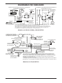
WIRINg DIAgRAMS
55,000, 85,000 and 125,000 Btu/Hr Models
Electrode/Electrodo/
Électrode
Orange**/
Naranja**/
Orange**
CONNECTION DIAGRAM/
DIAGRAMA DE CONEXIONES/
SCHÉMA DE CONNEXION
Green/Verde/Vert
• If any original wiring as supplied with the heater must be replaced, it must be replaced with type
AWG 105° C wire or its equivalent except as indicated (*Type SF2-200. **UL Style 3257 250° C)
• Si es necesario reemplazar algún cable suministrado originalmente con el calentador, éste se debe
reemplazar con cable tipo AWG 105° C o su equivalente, excepto cuando se indica locontrario
(*Tipo SF2-200. **UL Style 3257 250° C)
• Si le câblage original fourni avec l'appareil de chauffage doit être remplacé, faites-le avec du câble de
type AWG 105° C ou son équivalent, sauf indication contraire (*Type SF2-200. **UL Style 3257 250° C)
High Limit Switch/
Interruptor de
límite alto/
Commutateur de
limite supérieure
Gas Valve/
Válvula de gas/Vanne de gaz
Green/
Verde/
Vert
Green/Verde/Vert
Motor/
Moteur
Flame Control/
Control de llama/
Contrôle de
la flamme
Line/Línea/Ligne
Neut/Neutral/Neutre
Valve/Válvula/Vanne
Ground/Tierra/Masse
White/Blanco/Blanc
White/
Blanco/
Blanc
White/Blanco/Blanc
Blue*/Azul*/Bleu*
Blue*/Azul*/Bleu*
Blue*/
Azul*/
Bleu*
Black/Negro/Noir
Black/Negro/Noir
Black/Negro/
Noir
Black/
Negro/
Noir
Black/Negro/Noir
Thermostat/
Termostato
Chassis Ground/
Conexión a tierra
del chasis/Masse
Chassis Ground/
Conexión a tierra
del chasis/Masse
Chassis Ground/
Conexión a tierra
del chasis/Masse
Line Cord/
Cable de alimentaión/
Cordon d'alimentation
Black** or Orange**/
Negro** o Naranja**/
Noir** ou orange**
L1
L2
White/Blanco/
Blanc
Blue*/Azul*/Bleu*
Blue*/Azul*/Bleu*
Blue/Azul/Bleu
White/Blanco/
Blanc
White/Blanco/Blanc
Black/
Negro/Noir
Black/Negro/Noir
Black/Negro/Noir
Black/Negro/Noir
Green/
Verde/
Vert
Orange/
Naranja
Orange/
Naranja
Orange/
Naranja
Orange/
Naranja
Thermocouple/Termopar
CONNECTION DIAGRAM/DIAGRAMA DE CONEXIONES/
DIAGRAMME DE CONNEXION
SCHEMATIC DIAGRAM/DIAGRAMA ESQUEMÁTICO/
DIAGRAMME DE CIRCUIT
Relay/Relé/Relais
Motor/
Moteur
Ignitor/
Encendedor/
Allumeur
High-Limit Switch/
Interruptor de
límite alto/
Commutateur de
limite supérieure
• If any original wiring as supplied with the heater must be replaced, it must be replaced with type AWG 105° C
wire or its equivalent except as indicated (*Type SF2-200. **UL Style 3257 250° C)
• Si es necesario reemplazar algún cable suministrado originalmente con el calentador, éste se debe reemplazar con
cable tipo AWG 105° C o su equivalente, excepto cuando se indica lo contrario (*Tipo SF2-200. **UL Style 3257 250° C)
* Si le câblage fourni avec l'appareil de chauffage doit être remplacé, faites-le avec du câble de type AWG 105° C
ou son équivalent, sauf indication contraire (*Type SF2-200. **UL Style 3257 250° C)
Line Cord/
Cable de línea/
Cordon électrique
Motor/
Moteur
High Limit Switch/
Interruptor de límite alto/
Interrupteur de
limite supérieure
White/Blanco/Blanc
Black/Negro/Noir
115V
60HZ
Gas
Valve
Relay/
Relé/
Relais
Thermocouple/
Termopar
Green/Verde/Vert
L1
L2
Ignitor/
Encendedor/
Allumeur
Válvula de gas/
Robinet de gaz
Electrode/Electrodo/
Électrode
Electrode/Electrodo/
Électrode
170,000 Btu/Hr Models

www.desatech.com
119143-01A 11
REPLACEMENT PARTS
WARNING: Use only original
replacement parts. This heater
Do not substitute or use generic
parts. Improper replacement
parts could cause serious or fa-
tal injuries. This will also protect
your warranty coverage for parts
replaced under warranty.
PARTS UNDER WARRANTY
Contact authorized dealers of this product. If
they can’t supply original replacement part(s),
either contact your nearest Parts Central or
call DESA Heating Products’ Technical Ser-
vice Department at 1-866-672-6040. When
calling DESA Heating Products, have ready:
• your name
• your address
• model and serial numbers of your heater
• how heater was malfunctioning
• purchase date
In most cases, we will ask you to return the
part to the factory.
PARTS NOT UNDER WARRANTY
Contact authorized dealers of this product. If
they can’t supply original replacement part(s),
either contact your nearest Parts Central or call
DESA Heating Products at 1-866-672-6040
for referral information. When calling DESA
Heating Products, have ready:
• model number of your heater
• the replacement part number
TECHNICAL SERVICE
You may have further questions about this heater.
If so, contact DESA Heating Products’ Technical
Service Department at 1-866-672-6040. When
calling, please have your model and serial num-
bers of your heater ready.
You can also visit DESA Heating Products’ Tech-
nical Service web site at www.desatech.com.
SERVICE PUBLICATIONS
You can purchase a service manual for $5.
Make check payable to DESA Heating Prod-
ucts. Send your request to DESA Heating
Products (address on back page). Be sure to
include the heater model number.
ACCESSORIES
Purchase accessories and parts from your
nearest dealer or service center. If they can
not supply an accessory or part, either contact
your nearest Parts Central (listed in the sepa-
rate Authorized Service Center booklet) or call
DESA Heating Products at 1-866-672-6040.
You can also write to the address listed on the
back page of this manual.
A POL adapter with excess flow check valve.

www.desatech.com
119143-01A12
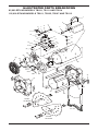
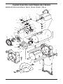
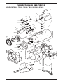
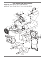
ILLUSTRATED PARTS BREAkDOWN
41
42
36
40
39
38
36
29
35
32
22
16
15
14
13
18
12
20
19
17
10
11
30
Detail A
Detail A
25
24
23
28
26
31
27
10
9
8
7
6
5
34
33
43
4
2
3
21
1
37
37

www.desatech.com
119143-01A 13
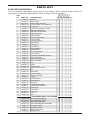
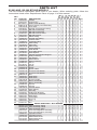
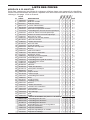
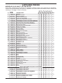
KEY
NO. PART NO. DESCRIPTION QTY.
1 118476-01 Handle • • • • 1
2 118472-01 Control Box • • • • 1
3 M11143-2 Strain Relief Bushing • • • • 1
4 098219-42 Power Supply Cord Assembly • • • • 1
5 100145-03 Fuel Tube • • • • 1
6 118796-01 Female Compression Fitting • • • • 1
7 114159-05 Ball Valve Assembly • • • • 1
8 113810-01 Ball Valve Knob Insert • • • • 1
9 118773-01 Ball Valve Knob • • • • 1
10 113870-01 Elbow Fitting • • • • 2
11 116981-01 Female Cap Fitting • • • • 1
12 097155-01 Control Valve • • • • 1
13 113869-01 Coupling Fitting • • • • 1
14 097809-04 Male Fitting • • • • 1
15 113794-01 Valve Nut • • • • 1
16 078978-03 Cap Sleeve • • • • 1
17 119401-01 Terminal Block • • • • 1
18 118506-01 Heat Shield • • • • 1
19 113867-01 Hi-Lo Mini Ignitor • • • • 1
20 114150-01 Steel Spacer • • • • 1
21 118802-01 Printed Circuit Board Support • • • • 3
22 113875-02 Relay Assembly • • • • 1
23 118780-01 Motor Grill Assembly • • • • 1
24 113880-02 Motor Assembly • • • • 1
25 113881-01 Fan • • • • 1
26 097805-04 Ignitor • • • • 1
27 097806-03 Ignitor Cable • • • • 1
28 101481-12 Thermal Limit Switch • • • • 1
29 098249-01 Nut • • • • 1
30 118497-02 Rear Plate • • • • 1
31 104146-05 Thermocouple • • • • 1
32 118514-01 Burner Assembly • • • • 1
33 118685-01 Injector • • • • 1
34 100146-01 Female Elbow • • • • 1
35 119496-01 Shell (Black) • • • • 1
36 118471-01 End Cap • • • • 2
37 119459-01 Hold Down Bracket • • • • 4
38 119497-01 Combustion Chamber • • • • 1
39 118477-03 Steel Tube • • • • 4
40 118475-01 Cord Cleat • • • • 2
41 118478-03 Foot Leg • • • • 2
42 118474-01 Foot • • • • 1
43 119631-01 Nut • • • • 1
PARTS AVAILABLE - NOT SHOWN
M9900-199 Wire Assembly, Black • • • • 1
M9900-200 Wire Assembly, White • • • • 1
101480-14 Wire Assembly, Blue • • • • 1
118774-04 Hose and Regulator Assembly • • • • 1
118687-01 Operation Decal • 1
118687-03 Operation Decal • • • 1
119144-01 Model Data Decal • • • • 1
119146-01 Wiring Decal • • • • 1
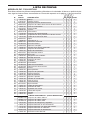
PARTS LIST
This list contains replaceable parts used in your heater. When ordering parts, follow the
instructions listed under Replacement Parts on page 11 of this manual.

www.desatech.com
119143-01A14
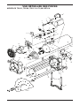
ILLUSTRATED PARTS BREAkDOWN
37
38
40
39
37
23
36
33
31
Detail A
125 Models
Detail B
85 Models
Detail A
Detail B
26
24
25
29
27
32
28
30
4
2
3
42
43
1
22
16
15
14
13
18
12
20
19
17
10
11
10
9
8
7
6
5
35
34
21
38
41
44

www.desatech.com
119143-01A 15
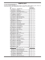
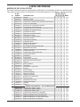
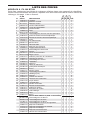
PARTS LIST
This list contains replaceable parts used in your heater. When ordering parts, follow the
instructions listed under Replacement Parts on page 11 of this manual.
KEY
NO. PART NO. DESCRIPTION QTY.
1 118476-01 Handle • • • • • • • 1
2 118472-01 Control Box • • • • • • • 1
3 M11143-2 Strain Relief Bushing • • • • • • • 1
4 098219-42 Power Supply Cord Assembly • • • • • • • 1
5 100145-03 Fuel Tube • • • • • • • 1
6 118796-01 Female Compression Fitting • • • • • • • 1
7 114159-05 Ball Valve Assembly • • • 1
114159-03 Ball Valve Assembly • • • • 1
8 113810-01 Ball Valve Knob Insert • • • • • • • 1
9 118773-01 Ball Valve Knob • • • • • • • 1
10 113870-01 Elbow Fitting • • • • • • • 2
11 116981-01 Female Cap Fitting • • • • • • • 1
12 097155-01 Control Valve • • • • • • • 1
13 113869-01 Coupling Fitting • • • • • • • 1
14 097809-04 Male Fitting • • • • • • • 1
15 113794-01 Valve Nut • • • • • • • 1
16 078978-03 Sleeve Cap • • • • • • • 1
17 119401-01 Terminal Block • • • • • • • 1
18 118506-01 Heat Shield • • • • • • • 1
19 113867-01 Hi-Lo Mini Ignitor • • • • • • • 1
20 114150-01 Steel Spacer • • • • • • • 1
21 118802-01 Printed Circuit Board Support • • • • • • • 3
22 113875-02 Relay Assembly • • • • • • • 1
23 118473-01 Fan Guard • • • • • • • 1
24 118482-01 Motor Mount • • • • • • • 1
25 113860-02 Motor Assembly • • • • • • • 1
26 113881-01 Fan 7" • • • 1
114160-01 Fan 8" • • • • 1
27 097805-03 Ignitor • • • • 1
097805-04 Ignitor • • • 1
28 097806-03 Ignitor Cable • • • • • • • 1
29 101481-04 Thermal Limit Switch • • • 1
101481-13 Thermal Limit Switch • • • • 1
30 098249-01 Nut • • • • • • • 1
31 118497-01 Rear Plate • • • • 1
118497-03 Rear Plate • • • 1
32 104146-05 Thermocouple • • • • • • • 1
33 118514-01 Burner Assembly • • • 1
118765-02 Burner Assembly • • • • 1
34 118685-02 Injector • • • 1
118685-03 Injector • • • • 1
35 100146-01 Female Elbow • • • • • • • 1
36 119496-02 Shell (Black) • • • • • • • 1
37 118471-01 End Cap • • • • • • • 2
38 119459-01 Hold Down Bracket • • • • • • • 4
39 119497-02 Combustion Chamber • • • • • • • 1
40 118477-01 Steel Tube • • • • • • • 4
41 118475-01 Cord Cleat • • • • • • • 2
42 118478-01 Foot Leg • • • • • • • 2
43 118474-01 Foot • • • • • • • 1
44 119631-01 Nut • • • • • • • 1
PARTS AVAILABLE - NOT SHOWN
M9900-199 Wire Assembly, Black • • • • • • • 1
M9900-200 Wire Assembly, White • • • • • • • 1
101480-14 Wire Assembly, Blue • • • • • • • 1
118774-01 Hose and Regulator Assembly • • • 1
118774-02 Hose and Regulator Assembly • • • • 1
118687-01 Operation Decal • 1
118687-03 Operation Decal • • • • • • 1
119144-02 Model Data Decal • • • 1
119144-03 Model Data Decal • • • • 1
119146-01 Wiring Decal • • • • • • • 1
TB111
TB114
TB112

www.desatech.com
119143-01A16
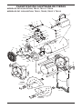
ILLUSTRATED PARTS BREAkDOWN
34
33
42
43
1
36
35
33
22
32
31
5
30
Detail A
Detail A
25
23
24
28
26
27
29
12
13
14
17
11
10
9
19
18
4
6
7
8
3
2
15
16
21
20
41
40
39
38
37
18
34
44

www.desatech.com
119143-01A 17
PARTS LIST
This list contains replaceable parts used in your heater. When ordering parts, follow the
instructions listed under Replacement Parts on page 11 of this manual.
KEY
NO. PART NO. DESCRIPTION QTY.
1 118476-01 Handle • • • 1
2 118770-01 Control Box • • • 1
3 M11143-2 Strain Relief Bushing • • • 1
4 098219-42 Power Supply Cord Assembly • • • 1
5 118767-01 Fuel Tube • • • 1
6 100146-01 Female Elbow • • • 1
7 118685-04 Injector • • • 1
8 M50114-02 Male Elbow • • • 1
9 114159-04 Ball Valve Assembly • • • 1
10 113810-01 Ball Valve Knob Insert • • • 1
11 118773-02 Ball Valve Knob • • • 1
12 098276-01 Plug • • • 1
13 118768-01 Street Tee • • • 1
14 098201-01 Solenoid Valve • • • 1
15 097809-04 Male Fitting • • • 1
16 078978-03 Sleeve Cap • • • 1
17 118766-01 Solenoid Valve Bracket • • • 1
18 113944-01 Thermostat Assembly • • • 1
19 119401-01 Terminal Block • • • 1
20 099123-01 Thermobulb Clip • • • 1
21 M50104-02 Shorty Bushing • • • 1
22 118473-01 Fan Guard • • • 1
23 118482-01 Motor Mount • • • 1
24 113941-02 Motor Assembly • • • 1
25 113950-01 Fan • • • 1
26 097805-03 Ignitor • • • 1
27 097806-03 Ignitor Cable • • • 1
28 101481-05 Thermal Limit Switch • • • 1
29 098249-01 Nut • • • 1
30 118497-01 Rear Plate • • • 1
31 118765-02 Burner Assembly • • • 1
32 119496-03 Shell (Black) • • • 1
33 118471-01 End Cap • • • 2
34 119459-01 Hold Down Bracket • • • 4
35 119497-03 Combustion Chamber • • • 1
36 118477-02 Steel Tube • • • 4
37 110287-01 DSI Control • • • 1
38 097776-01 Universal Bushing • • • 1
39 113961-01 Thermostat Knob • • • 1
40 118919-01 Heat Shield • • • 1
41 118475-01 Cord Cleat • • • 2
42 118478-02 Foot Leg • • • 2
43 118474-01 Foot • • • 1
44 119631-01 Nut • • • 1
PARTS AVAILABLE - NOT SHOWN
M16841-80 Wire Assembly, White • • • 1
M9900-170 Wire Assembly, Black • • • 1
101480-15 Wire Assembly, Blue • • • 1
116774-03 Hose and Regulator Assembly • • • 1
118687-04 Operation Decal • • • 1
119144-04 Model Data Decal • • • 1
119146-02 Wiring Decal • • • 1
099504-08 Warning Decal • • • 1
110267-02 DSI Control Harness • • • 1

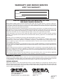
WARRANTy AND REPAIR SERVICE
kEEP THIS WARRANTy
2701 Industrial Drive
P.O. Box 90004
Bowling Green, KY 42102-9004
LIMITED WARRANTIES FOR NEW AND FACTORy
RECONDITIONED PRODUCTS
New Products: DESA Heating Products warrants this heater and any parts thereof, to be free of defects in
materials and workmanship for one (1) year from the date of rst purchase, when operated and maintained
in accordance with the manufacturer's instructions. These warranties are extended only to the original retail
purchaser, when proof of purchase is provided.
Factory Reconditioned Heaters: DESA Heating Products warrants this factory reconditioned heater and any
parts thereof, to be free of defects in materials and workmanship for thirty (30) days from the date of rst
purchase, when operated and maintained in accordance with the manufacturer's instructions. These war-
ranties are extended only to the original retail purchaser, when proof of purchase is provided.
These warranties cover only the cost of parts and labor required to restore the product to proper operating
condition. Transportation and incidental costs associated with warranty repairs are not reimbursable under
this warranty.
Warranty service is available only through authorized dealers and service centers.
This warranty does not cover defects resulting from misuse, abuse, negligence, accidents, lack of proper
maintenance, normal wear, alteration, modication, tampering, contaminated fuels, repair using improper
parts or repair by anyone other than an authorized dealer or service center. Routine maintenance is the
responsibility of the owner.
THIS EXPRESS WARRANTY IS GIVEN IN LIEU OF ANY OTHER WARRANTY EITHER EXPRESSED
OR IMPLIED, INCLUDING WARRANTIES OF MERCHANTABILITY AND FITNESS FOR A PARTICULAR
PURPOSE.
DESA Heating Products assumes no responsibility for indirect, incidental or consequential damages. Some
states do not allow the exclusion or limitation of incidental or consequential damages or limitations or exclu-
sions may not apply to you. This limited warranty gives you specic legal rights and you may also have other
rights which vary from state to state.
We reserve the right to amend these specications at any time without notice. The only warranty applicable
is our standard written warranty. We make no other warranty, expressed or implied.
WARRANTy SERVICE
Should your heater require service, return it to your nearest authorized service center. Proof of purchase
must be presented with the heater. The heater will be inspected. A defect may be caused by faulty materials
or workmanship. If so, DESA Heating Products will repair or replace the heater without charge.
REPAIR SERVICE
Return your heater to your nearest authorized service center. Repairs not covered by the warranty will be
billed at standard prices. Each Service Center is independently owned and operated. We reserve the right
to amend these specications at any time without notice. When writing, always include model number and
serial number. For information, write:
Model
Serial No.
Date of Purchase
82 Akron Road
Toronto, Ontario
M8W 1T2
119143-01
Rev. A
06/06
Page is loading ...
Page is loading ...
Page is loading ...
Page is loading ...
Page is loading ...
Page is loading ...
Page is loading ...
Page is loading ...
Page is loading ...

www.desatech.com
119143-01A10
DIAGRAMAS DE CABLEADO
Modelos de 55,000, 85,000 y 125,000 BTU/h
Electrode/Electrodo/
Électrode
Orange**/
Naranja**/
Orange**
CONNECTION DIAGRAM/
DIAGRAMA DE CONEXIONES/
SCHÉMA DE CONNEXION
Green/Verde/Vert
• If any original wiring as supplied with the heater must be replaced, it must be replaced with type
AWG 105° C wire or its equivalent except as indicated (*Type SF2-200. **UL Style 3257 250° C)
• Si es necesario reemplazar algún cable suministrado originalmente con el calentador, éste se debe
reemplazar con cable tipo AWG 105° C o su equivalente, excepto cuando se indica locontrario
(*Tipo SF2-200. **UL Style 3257 250° C)
• Si le câblage original fourni avec l'appareil de chauffage doit être remplacé, faites-le avec du câble de
type AWG 105° C ou son équivalent, sauf indication contraire (*Type SF2-200. **UL Style 3257 250° C)
High Limit Switch/
Interruptor de
límite alto/
Commutateur de
limite supérieure
Gas Valve/
Válvula de gas/Vanne de gaz
Green/
Verde/
Vert
Green/Verde/Vert
Motor/
Moteur
Flame Control/
Control de llama/
Contrôle de
la flamme
Line/Línea/Ligne
Neut/Neutral/Neutre
Valve/Válvula/Vanne
Ground/Tierra/Masse
White/Blanco/Blanc
White/
Blanco/
Blanc
White/Blanco/Blanc
Blue*/Azul*/Bleu*
Blue*/Azul*/Bleu*
Blue*/
Azul*/
Bleu*
Black/Negro/Noir
Black/Negro/Noir
Black/Negro/
Noir
Black/
Negro/
Noir
Black/Negro/Noir
Thermostat/
Termostato
Chassis Ground/
Conexión a tierra
del chasis/Masse
Chassis Ground/
Conexión a tierra
del chasis/Masse
Chassis Ground/
Conexión a tierra
del chasis/Masse
Line Cord/
Cable de alimentaión/
Cordon d'alimentation
Black** or Orange**/
Negro** o Naranja**/
Noir** ou orange**
L1
L2
White/Blanco/
Blanc
Blue*/Azul*/Bleu*
Blue*/Azul*/Bleu*
Blue/Azul/Bleu
White/Blanco/
Blanc
White/Blanco/Blanc
Black/
Negro/Noir
Black/Negro/Noir
Black/Negro/Noir
Black/Negro/Noir
Green/
Verde/
Vert
Orange/
Naranja
Orange/
Naranja
Orange/
Naranja
Orange/
Naranja
Thermocouple/Termopar
CONNECTION DIAGRAM/DIAGRAMA DE CONEXIONES/
DIAGRAMME DE CONNEXION
SCHEMATIC DIAGRAM/DIAGRAMA ESQUEMÁTICO/
DIAGRAMME DE CIRCUIT
Relay/Relé/Relais
Motor/
Moteur
Ignitor/
Encendedor/
Allumeur
High-Limit Switch/
Interruptor de
límite alto/
Commutateur de
limite supérieure
• If any original wiring as supplied with the heater must be replaced, it must be replaced with type AWG 105° C
wire or its equivalent except as indicated (*Type SF2-200. **UL Style 3257 250° C)
• Si es necesario reemplazar algún cable suministrado originalmente con el calentador, éste se debe reemplazar con
cable tipo AWG 105° C o su equivalente, excepto cuando se indica lo contrario (*Tipo SF2-200. **UL Style 3257 250° C)
* Si le câblage fourni avec l'appareil de chauffage doit être remplacé, faites-le avec du câble de type AWG 105° C
ou son équivalent, sauf indication contraire (*Type SF2-200. **UL Style 3257 250° C)
Line Cord/
Cable de línea/
Cordon électrique
Motor/
Moteur
High Limit Switch/
Interruptor de límite alto/
Interrupteur de
limite supérieure
White/Blanco/Blanc
Black/Negro/Noir
115V
60HZ
Gas
Valve
Relay/
Relé/
Relais
Thermocouple/
Termopar
Green/Verde/Vert
L1
L2
Ignitor/
Encendedor/
Allumeur
Válvula de gas/
Robinet de gaz
Electrode/Electrodo/
Électrode
Electrode/Electrodo/
Électrode
Modelos de 170,000 BTU/h
Page is loading ...
Page is loading ...
Page is loading ...
Page is loading ...
Page is loading ...
Page is loading ...
Page is loading ...
Page is loading ...
Page is loading ...
Page is loading ...
Page is loading ...
Page is loading ...
Page is loading ...
Page is loading ...
Page is loading ...
Page is loading ...
Page is loading ...
Page is loading ...
Page is loading ...

www.desatech.com
119143-01A12
DIAGRAMMES DE CÂBLAGE
Modèles à 55 000, 85 000 et 125 000 BTU/h
Electrode/Electrodo/
Électrode
Orange**/
Naranja**/
Orange**
CONNECTION DIAGRAM/
DIAGRAMA DE CONEXIONES/
SCHÉMA DE CONNEXION
Green/Verde/Vert
• If any original wiring as supplied with the heater must be replaced, it must be replaced with type
AWG 105° C wire or its equivalent except as indicated (*Type SF2-200. **UL Style 3257 250° C)
• Si es necesario reemplazar algún cable suministrado originalmente con el calentador, éste se debe
reemplazar con cable tipo AWG 105° C o su equivalente, excepto cuando se indica locontrario
(*Tipo SF2-200. **UL Style 3257 250° C)
• Si le câblage original fourni avec l'appareil de chauffage doit être remplacé, faites-le avec du câble de
type AWG 105° C ou son équivalent, sauf indication contraire (*Type SF2-200. **UL Style 3257 250° C)
High Limit Switch/
Interruptor de
límite alto/
Commutateur de
limite supérieure
Gas Valve/
Válvula de gas/Vanne de gaz
Green/
Verde/
Vert
Green/Verde/Vert
Motor/
Moteur
Flame Control/
Control de llama/
Contrôle de
la flamme
Line/Línea/Ligne
Neut/Neutral/Neutre
Valve/Válvula/Vanne
Ground/Tierra/Masse
White/Blanco/Blanc
White/
Blanco/
Blanc
White/Blanco/Blanc
Blue*/Azul*/Bleu*
Blue*/Azul*/Bleu*
Blue*/
Azul*/
Bleu*
Black/Negro/Noir
Black/Negro/Noir
Black/Negro/
Noir
Black/
Negro/
Noir
Black/Negro/Noir
Thermostat/
Termostato
Chassis Ground/
Conexión a tierra
del chasis/Masse
Chassis Ground/
Conexión a tierra
del chasis/Masse
Chassis Ground/
Conexión a tierra
del chasis/Masse
Line Cord/
Cable de alimentaión/
Cordon d'alimentation
Black** or Orange**/
Negro** o Naranja**/
Noir** ou orange**
L1
L2
White/Blanco/
Blanc
Blue*/Azul*/Bleu*
Blue*/Azul*/Bleu*
Blue/Azul/Bleu
White/Blanco/
Blanc
White/Blanco/Blanc
Black/
Negro/Noir
Black/Negro/Noir
Black/Negro/Noir
Black/Negro/Noir
Green/
Verde/
Vert
Orange/
Naranja
Orange/
Naranja
Orange/
Naranja
Orange/
Naranja
Thermocouple/Termopar
CONNECTION DIAGRAM/DIAGRAMA DE CONEXIONES/
DIAGRAMME DE CONNEXION
SCHEMATIC DIAGRAM/DIAGRAMA ESQUEMÁTICO/
DIAGRAMME DE CIRCUIT
Relay/Relé/Relais
Motor/
Moteur
Ignitor/
Encendedor/
Allumeur
High-Limit Switch/
Interruptor de
límite alto/
Commutateur de
limite supérieure
• If any original wiring as supplied with the heater must be replaced, it must be replaced with type AWG 105° C
wire or its equivalent except as indicated (*Type SF2-200. **UL Style 3257 250° C)
• Si es necesario reemplazar algún cable suministrado originalmente con el calentador, éste se debe reemplazar con
cable tipo AWG 105° C o su equivalente, excepto cuando se indica lo contrario (*Tipo SF2-200. **UL Style 3257 250° C)
* Si le câblage fourni avec l'appareil de chauffage doit être remplacé, faites-le avec du câble de type AWG 105° C
ou son équivalent, sauf indication contraire (*Type SF2-200. **UL Style 3257 250° C)
Line Cord/
Cable de línea/
Cordon électrique
Motor/
Moteur
High Limit Switch/
Interruptor de límite alto/
Interrupteur de
limite supérieure
White/Blanco/Blanc
Black/Negro/Noir
115V
60HZ
Gas
Valve
Relay/
Relé/
Relais
Thermocouple/
Termopar
Green/Verde/Vert
L1
L2
Ignitor/
Encendedor/
Allumeur
Válvula de gas/
Robinet de gaz
Electrode/Electrodo/
Électrode
Electrode/Electrodo/
Électrode
Modèles à 170 000 BTU/h
Page is loading ...
Page is loading ...
Page is loading ...
Page is loading ...
Page is loading ...
Page is loading ...
Page is loading ...
Page is loading ...
-
 1
1
-
 2
2
-
 3
3
-
 4
4
-
 5
5
-
 6
6
-
 7
7
-
 8
8
-
 9
9
-
 10
10
-
 11
11
-
 12
12
-
 13
13
-
 14
14
-
 15
15
-
 16
16
-
 17
17
-
 18
18
-
 19
19
-
 20
20
-
 21
21
-
 22
22
-
 23
23
-
 24
24
-
 25
25
-
 26
26
-
 27
27
-
 28
28
-
 29
29
-
 30
30
-
 31
31
-
 32
32
-
 33
33
-
 34
34
-
 35
35
-
 36
36
-
 37
37
-
 38
38
-
 39
39
-
 40
40
-
 41
41
-
 42
42
-
 43
43
-
 44
44
-
 45
45
-
 46
46
-
 47
47
-
 48
48
-
 49
49
-
 50
50
-
 51
51
-
 52
52
-
 53
53
-
 54
54
-
 55
55
-
 56
56


Ask a question and I''ll find the answer in the document
Finding information in a document is now easier with AI
in other languages
- français: Desa TB101 Manuel utilisateur
- español: Desa TB101 Manual de usuario
Related papers
Other documents
-
Procom 200058 Operating instructions
-
 ProCom Heating 200058 User manual
-
ProCom Heating PP40FA-C User manual
-
-
 Avenger FBDFA60V User manual
-
 ProCom Heating PCFA40 User guide
-
 Mi-T-M MH-0375-LM10 User manual
-
Vanguard Heating Indoor Fireplace WMH26TNB User manual
-
Master TB116A Owner's manual
-
 ProCom Heating PP125FAV-C User manual


