Voyager MSR200 Owner's manual

Category
Car media receivers
Type
Owner's manual
MSR2007
2
CONTENTS
Safety Information .............................................................................................. 1
Installation........................................................................................................... 2
Wiring................................................................................................................... 4
Basic Operation .................................................................................................. 5
Tuner Operation.................................................................................................. 7
Sirius Radio Operation....................................................................................... 8
iPod Operation.................................................................................................... 9
Care and Maintenance...................................................................................... 10
Troubleshooting................................................................................................ 10
Specifications ...................................................................................................10
CONTENIDO
Información de Seguridad................................................................................ 11
Instalación......................................................................................................... 12
Cableado............................................................................................................ 14
Operación Básica ............................................................................................. 15
Operación del Sintonizador............................................................................. 17
Operación de Radio Sirius............................................................................... 18
Operación del iPod........................................................................................... 19
Cuidado y Mantenimiento................................................................................ 20
Solución de Problemas.................................................................................... 20
Especificaciones ...............................................................................................20
TABLE DES MATIÈRES
Informations sur la securite............................................................................. 21
Installation......................................................................................................... 22
Câblage.............................................................................................................. 24
Operation de Base............................................................................................ 25
Operation tuner................................................................................................. 27
Operation radio Sirius...................................................................................... 28
Operation iPod.................................................................................................. 29
Soin et entretien................................................................................................ 30
Dépannage ........................................................................................................ 30
Specifications ...................................................................................................30
MSR2007
1
SAFETY INFORMATION
When Boating
Keep the volume level Iow enough to be aware of your surroundings.
Protect from Water
Do not submerge or expose the product directly to water, as this can cause electrical shorts,
fire or other damage.
Protect from High Temperatures
Exposure to direct sunlight for an extended period of time can produce very high temperatures
inside your vessel. Give the interior a chance to cool down before starting playback.
Do not mount radio within close proximity of engine compartment.
Use the Proper Power Supply
This product is designed to operate with a 12 volt DC negative ground battery system.
WARNING:
DO NOT OPEN, DISASSEMBLE OR ALTER THE UNIT IN ANY WAY. Doing so may
result in fire, electric shock or product damage.
USE THE CORRECT AMPERE RATING WHEN REPLACING FUSE. Failure to do so
may result in fire, electric shock or product damage.
DO NOT INSTALL IN LOCATIONS THAT MIGHT HINDER VEHICLE OPERATION. Doing
so may obstruct vision or hamper movement which can result in a serious accident.
INSTALL THE WIRING SO THAT IT IS NOT CRIMPED OR PINCHED BY SCREWS OR
SHARP METAL EDGES. Route the cables away from moving parts or sharp pointed
edges. This will prevent crimping and damage to the wiring. If the wiring must pass
through a metal hole, be sure to use a rubber grommet to prevent the wire's insulation
from being cut by the metal edge of the hole. It is also recommended to apply sealing
caulk to any opening that may potentially allow water to enter.
Be sure to choose a location that is flat and has clearance above the unit to prevent any
damage, as well as allow for ventilation.
Before drilling any holes, carefully inspect the area underneath and behind the mounting
surface where the devices will be mounted to make sure it will not interfere with existing
wires, fuel lines, the fuel tank or any other objects that could be damaged.
Always disconnect the vehicle negative battery terminal to prevent accidental shorting
during installation.
MSR2007
2
INSTALLATION
Before You Begin
Before you begin, always disconnect the battery negative terminal.
Important Notes
Before final installation, test the wiring connections to make sure the unit is connected
properly and the system works.
Use only the parts included with the unit to ensure proper installation. The use of
unauthorized parts can cause malfunctions.
Consult with your nearest dealer if installation requires the drilling of holes or other
modifications to your vessel.
Install the unit where it does not interfere with driving and cannot injure passengers if
there is a sudden or emergency stop.
Avoid installing the unit where it will be subject to high temperatures from direct sunlight,
hot air, or from a heater, or where it would be subject to excessive dust, dirt or vibration.
Wired Commander Mounting
1. Choose a mounting area for the wired commander that is clean and flat, allowing the rear
gasket to fully seal to the mounting surface.
2. Secure the wired commander using either of the recommended mounting methods
detailed in the diagrams below.
7/8” HOLE REQUIRED
FOR CABLE
M4 MOUNTING SCREWS (4-PCS)
MINIMUM SCREW LENGTH 1 1/2”
7/8” HOLE REQUIRED FOR CABL
E
M5X8 SCREWS REQUIRED FOR MOUNTING
MAXIMUM SCREW DEPTH IN COMMANDER 1/4”
MSR2007
3
Tuner/Amplifier Mounting
1. Choose a mounting area for the tuner/amp module that will provide plenty of ventilation to
prevent the amplifier from overheating. The tuner/amp module can be mounted in the hor-
izontal or vertical position. Please note that when mounting in vertical position, do not
mount with the harness exit points facing straight up, as water can collect around the
chassis in these areas.
2. Attach the 4 rubber mounting feet, provided, to the bottom of the tuner/amp metal plate.
This will provide clearance from surface moisture and promote good ventilation for the
heat sink.
3. Using the shortest length of the recommended size screws possible, mount the tuner/
amplifier as detailed in the diagram on the right.
4. Route the tuner/ amplifier harness and cable throughout the vessel as required. Keep
some slack in the harness/ cables so it won't be too tight, as this can cause damage to the
wires.
5. Follow the wiring diagram carefully and make certain all connections are secure and
insulated with crimp connectors or electrical tape to ensure proper operation.
6. After completing the wiring connections, reconnect the negative terminal on the battery
and turn the unit on to confirm operation (vessel accessory switch must be on). If the unit
does not operate, disconnect battery, recheck all wiring and refer to the trouble-shooting
guide located in the back of the manual.
Reconnect Battery
When wiring is complete, reconnect the battery negative terminal.
STAINLESS STEEL M4 SCREWS REQUIRED
WITH MINIMUM LENGTH OF 1”
1 1/2” PILOT HOLES FOR SUPPLIED SELF-STARTING SCREWS
180 PILOT HOLES WHEN USING THREADED MACHINE SCREWS
1 3/4” HOLE REQUIRED FOR
CABLE/CONNECTOR
REMOVABLE RUBBER FEET
4 PLACES
MSR2007
5
BASIC OPERATION
Power On/Off
Press any button on the front panel to turn the unit on. Press the POWER button (1) to turn the
unit off. The unit will resume the last mode (Tuner, Aux, etc.). The POWER button is illuminated
whenever the +12V DC Switched (red wire) is powered, regardless of whether the unit is on or
off.
Volume Control
To increase the volume, press the VOLUME + button (2a). To decrease the volume, press the
VOLUME - button (2b). The maximum volume level is “46”.
Mute
Press the MUTE button (17) on the control panel to mute the audio output. Press MUTE again
to restore the audio output to the previous level.
Mode
Press the MODE button (4) on the control panel to select a different mode of operation, as
indicated on the display panel. Available modes include Tuner, SIRIUS, iPod and AUX In.
NOTE: iPod and SIRIUS mode will be skipped if the module is not installed.
Reset
The reset button should be activated for the following reasons:
initial installation of the unit when all wiring is completed
function buttons do not operate
error symbol on the display
Use a ball point pin or thin metal object to press the RESET button, located on the tuner box.
You can recover factory default settings using the RESUME function located on the system
menu. With “YES” flashing, press the MODE button (4) to activate.
Audio Menu
Press the AUDIO button (3) on the control panel to access the audio menu. You can navigate
through the audio menu items by pressing the AUDIO button repeatedly. Once the desired
menu item appears on the display, adjust that option by pressing the VOLUME +/- buttons (2)
within 5 seconds. The unit will automatically exit the audio menu after five seconds of inactivity.
The following menu items can be adjusted.
Bass Level
Use the VOLUME buttons to adjust the Bass level range from “-6” to “+6”.
Treble Level
Use the VOLUME buttons to adjust the Treble level range from “-6” to “+6”.
Balance
Use the VOLUME buttons to adjust the Balance between the left and right speakers from “L12”
(full left) to “R12” (full right).
Fader
Use the VOLUME buttons to adjust the Fader between the rear and front speakers from “R12”
(full rear) to “F12” (full front).
3
2a
4
11
12
13
14
15
16
17
1
2b
SAT
AUDIO
INFO
18
19
5
6 7
8
9
10
20
MSR2007
6
System Menu
1. Press and hold the AUDIO button (3) for more than 3 seconds to enter the system menu.
“MENU” will appear on the display, followed by the first menu item, “CONTRAST.”
2. Press the TUNE/TRK >>| or |<< button (19, 18) or press the AUDIO button repeatedly to
navigate the system menu and select the desired item.
3. Press the VOLUME +/- buttons (2) to adjust the selected menu item.
4. Press the AS/PS button to return to the previous operation immediately or wait for 5
seconds to return automatically.
The following items can be adjusted:
CONTRAST (0 – 10): Set LCD contrast.
LOW BATT (ON/OFF): Monitor voltage on ACC line.
AREA (USA/LATIN/EUROPE): Set frequency spacing for various regions.
VOL PGM (0 – 46): Select an automatic turn-on volume.
BEEP TONE (ON/OFF): Turn the audible beep ON/OFF (heard when functions/buttons
are selected). NOTE: Beep tone off will not affect LOW BATT audible tone.
RESUME: Return the EEPROM to factory default set up values and reset the Sirius Tuner
Settings. "Yes" will blink on the LCD to confirm. Press MODE to select.
LOW BATTERY Operation
If LOW BATT is set to “ON”, a alarm will sound (8 beeps every 30 sec) when the voltage drops
to 10.8V (+/- 0.03V). A visual warning (LOBA) will appear flashing (8 fl ashes every 30 sec) in
the lower left corner of the LCD display.
NOTE: “OFF” is the default setting for LOW BATT. If the audio is muted or the volume is
set to 0, the audible beep will not be heard.
Equalizer
Press the EQ button (11) to turn on the equalization function and select between five pre-
defined bass and treble curves: OFF > POP > JAZZ > CLASSIC > BEAT > ROCK.
iX-Bass
Press and hold the EQ/IX-BASS button (11) toggle loudness on/off. When listening to music at
low volumes, this feature will boost the bass range to compensate for the characteristics of
human hearing.
Auxiliary Input
To access an auxiliary device:
1. Connect the portable audio player to the AUX IN cables on the back of the tuner box.
2. Press the MODE button (4) to select Aux In mode.
3. Press MODE again to cancel Aux In mode and go to the next mode.
Liquid Crystal Display (LCD)
The current frequency and activated functions are shown on the LCD panel (23).
NOTE: LCD panels may take longer to respond when subjected to cold temperatures for
an extended period of time. In addition, the visibility of the numbers on the LCD may
decrease slightly. The LCD display will return to normal when the temperature increases
to a normal range.
Scroll
When the information is too long to be displayed on the LCD, press and hold the INFO/
SCROLL button (12) to view the entire title. The information will scroll twice and then return to
abbreviated text.
Quick Exit Hot Key
In the following modes and conditions, press the AS/PS button < 3 seconds to quickly exit the
current operation without waiting for the system default time out:
System menu operation
Searching mode
Audio menu operation
• LOCAL: this model favors access to local stations whose signals are much stronger;
thereby improving radio reception.
• DISTANT: this is terminate the local receive mode to normal receive mode.
MSR2007
7
TUNER OPERATION
Select a Band
Press the BAND button (16) to change between three FM bands and two AM (MW) bands.
Manual Tuning
Press the TUNE/TRK >>| or |<< buttons (18, 19) to seek stations up/down step by step.
Auto Seek Tuning
Press and hold the TUNE/TRK >>| or |<< buttons (18, 19) to automatically seek the next or
previous strong station.
Preset Stations
Six numbered preset buttons store and recall stations for each band.
Store a Station
Select a band (if needed), then select a station. Press and hold a preset button (5-10) for two
seconds. The preset number will appear in the display.
Recall a Station
Select a band (if needed). Press a preset button (5-10) to select the corresponding stored
station.
Automatically Store / Preset Scan (AS/PS)
Automatically Store
Select a band (if needed). Press and hold the AS/PS (15) button for more than three seconds
to automatically select six strong stations and store them in the current band. The new stations
replace any stations already stored in that band.
NOTE: During Auto Store (AS), the tuner will default to “Local” mode while scanning the
band initially. After scanning the entire band once, the unit will switch to “Distant” mode
for all subsequent Auto Store tuning.
Preset Scan
Select a band (if needed). Press AS/PS (15) to scan stations stored in the current band. The
unit will pause for ten seconds at each preset station. Press AS/PS again to stop scanning
when the desired station is reached.
Local/Distant Reception (LO/DX)
During radio operation, received signals are usually in stereo mode as indicated by the “ST”
icon. However, when the signals are weak or intermittent, you can activate the Local (LOC)
mode by pressing the LO/DX button (20). This mode favors access to local stations whose
signals are much stronger; thereby improving radio reception. Press the LO/DX button again to
terminate Local receive mode.
3
2a
4
11
12
13
14
15
16
17
1
2b
SAT
AUDIO
INFO
18
19
5
6 7
8
9
10
20
MSR2007
8
SIRIUS RADIO OPERATION
Switching to SIRIUS Mode (Requires Optional Sirius Tuner)
Press the MODE button (4) to change the mode to Sirius radio mode.
Accessing your SIRIUS ID
1. In Sirius mode, press and hold the BAND/SEARCH button (16) to select DIRECT mode.
2. Press the MODE button (4) to activate Direct mode.
3. Press the MODE button for each digit to enter “000”.
4. Press MODE again to confirm. This will display the Sirius ID number for your tuner.
5. The Sirius ID number will scroll twice and then freeze with the first 11 digits on the display.
Press the INFO/SCROLL button (12) to display the remaining digit.
Selecting a Band
In Sirius mode, press the BAND button (16) to access the Sirius user-preset channel groups in
the following order: SR-1, SR-2, SR-3.
Category Tuning
1. Press the CAT - /+ buttons (13/14) to change the category. Each category title and song
title will be displayed in increments.
2. While in the category mode, press the CAT - /+ buttons again to view category names.
(The lowest channel number within the chosen category will always be the default first
channel tuned.)
3. Press the MODE button (4) or the TUNE/TRK |<< / >>| buttons (18/19) to choose desired
channels in that category.
4. Press the TUNE/TRK buttons to select a channel within the chosen category.
5. Press MODE to confirm channel selection.
Channel Up/Down Tuning
Press the TUNE/TRK |<< / >>| buttons (18/19) to search for a channel. Press and hold the
TUNE/TRK buttons to fast search.
Storing Preset Channels
The preset buttons (5-10) can be used to store 6 channels, allowing convenient access to your
favorite channels.
Programming Channels
1. Select the channel you want to store in memory.
2. Press and hold a preset button (5-10) until the corresponding preset button number
appears.
3. Repeat steps 1 and 2 to program additional channels.
Quick Tuning
Press one of the six preset buttons (5-10) to select a preset channel directly.
Channel Direct Access Searching
1. Press and hold the BAND/SEARCH button (16) to access Direct Tune mode. “DIRECT-T”
appears on the display for a few seconds.
2. Press the MODE button (4) to confirm.
3. Press the TUNE/TRK |<< / >>| buttons (18/19) to move between the three digits.
4. Use the VOLUME +/- buttons (2) to select a number for each position.
5. Press the MODE button to confirm each digit.
6. Press the MODE button again to tune to the selected file.
Alternate Display Information
Press INFO/SCROLL button (12) to change the display information in the following order:
ARTIST NAME > SONG TITLE > CATEGORY > CHANNEL NAME.
Satellite Signal Strength
The display will indicate satellite reception strength as shown below.
Signal Strength Strength Display
No Signal
Weak
Good
Excellent
3
2a
4
11
12
13
14
15
16
17
1
2b
SAT
AUDIO
INFO
18
19
5
6 7
8
9
10
20
MSR2007
9
IPOD OPERATION
This unit is equipped with an iPod ready function that will allow you to control your iPod (if
compatible) using the control panel control buttons. The following iPod versions are supported:
iPod 3G (firmware version 2.2 only)
iPod Mini
iPod 4G
iPod Photo
iPod Nano
iPod 5G (Video)
NOTE: iPod and iPod Cable sold separately.
Accessing iPod Mode
The unit will automatically switch to iPod mode
when an iPod is plugged into the iPod cable.
To return to the iPod menu from any other source,
press the MODE button (4) on the control panel or
remote control until “iPod” appears on the display.
Turning the iPod On/Off
The iPod power turns on automatically when an
iPod is connected to 30-pin iPod cable, as long as
the vehicle ignition is turned on. You can turn the
iPod off by disconnecting it from the cable or by
turning the ignition off. When the ignition is turned
off, the iPod will pause and then enter sleep mode after 2 minutes. While the iPod is
connected, the power cannot be turned on or off from the iPod itself.
NOTE: The iPod will continuously recharge when connected to the unit, as long as the
vehicle ignition is turned on.
Controlling Playback
Pausing Playback
During playback, press the 1/>|| button (8) to pause the iPod player. “Pause” will appear on the
LCD. Press 1/>|| again to resume playback.
Repeat Play
During playback, press the 3/RPT button (5) to repeat the current song. “Repeat” will appear
on the LCD. Press 3/RPT again to stop repeat playback.
Random Play
During playback, press the 4/RDM button (7) to play all songs in the current category in
random order. Random play will begin once the current song has finished playing. “Shuffle” will
appear on the LCD. Press 4/RDM again to stop random playback.
Selecting Tracks
During playback, press the TUNE/TRK |<< / >>| button (18/19) to play the previous or next
track in the current category. Press the TUNE/TRK |<< button (18) once to play the song from
the start position or press TUNE/TRK |<< twice to play the previous track.
Press and hold the TUNE/TRK |<< / >>| button (18/19) to fast reverse/forward the song.
NOTE: If you press and hold the TUNE/TRK |<< / >>| button to change the current song
to the previous/next song, you will exit fast reverse/forward mode.
Alternate Display Information
Press INFO/SCROLL button (12) to change the display information in the following order:
ARTIST NAME > SONG TITLE > FOLDER NAME.
Search Mode
Press and hold the BAND/SEARCH button (16) to enter iPod search mode. Press BAND/
SEARCH again to access Playlist, Artist, Album, Genre, Song, or Composer (consecutively).
When search mode is selected, press the MODE button (4) to confirm selection. Use the
VOLUME +/- buttons (2) to navigate through various list selections. Press MODE (4) to make
your final selection.
iPod CABLE
iPod
photo
iPod iPod
mini
iPod
nano
iPod
Video
MA IR NE
3
2a
4
11
12
13
14
15
16
17
1
2b
SAT
AUDIO
INFO
18
19
5
6 7
8
9
10
20
MSR2007
10
CARE AND MAINTENANCE
Keep the product dry. If it does get wet, wipe it dry immediately. Liquids might contain
minerals that can corrode the electronic circuits.
Keep the product away from dust and dirt, which can cause premature wear of parts.
Handle the product gently and carefully. Dropping it can damage circuit boards and
cases, and can cause the product to work improperly.
Wipe the product with a dampened cloth occasionally to keep it looking new. Do not use
harsh chemicals, cleaning solvents, or strong detergents to clean the product.
Use and store the product only in normal temperature environments. High temperature
can shorten the life of electronic devices, damage batteries, and distort or melt plastic
parts.
Ignition
The most common source of noise in reception is the ignition system. This is a result of the
radio being placed close to the ignition system (engine). This type of noise can be easily
detected because it will vary in intensity of pitch with the speed of the engine.
Usually, the ignition noise can be suppressed considerably by using a radio suppression type
high voltage ignition wire and suppressor resistor in the ignition system. (Most vessels employ
this wire and resistor but it may be necessary to check them for correct operation.) Another
method of suppression is the use of additional noise suppressors. These can be obtained from
most CB/A radio or electronic supply shops.
Interference
Radio reception in a moving environment is very different from reception in a stationary
environment (home). It is very important to understand the difference.
AM reception will deteriorate when passing under a bridge or when passing under high voltage
lines. Although AM is subject to environmental noise, it has the ability to received at great
distance. This is because broadcasting signals follow the curvature of the earth and are
reflected back by the upper atmosphere.
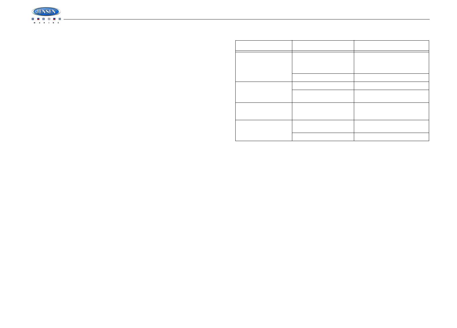
TROUBLESHOOTING
SPECIFICATIONS
FM Radio
Frequency Coverage (USA) . . . . . . . . . . . . . . . . . . . . . . . . . . . . . . . . . . . 87.5 to 107.9 MHz
Frequency Coverage (Europe) . . . . . . . . . . . . . . . . . . . . . . . . . . . . . . . . . . 87.5 to 108 MHz
Sensitivity (S/N=30dB) . . . . . . . . . . . . . . . . . . . . . . . . . . . . . . . . . . . . . . . . . . . . . . . . . . 4µV
Image Rejection . . . . . . . . . . . . . . . . . . . . . . . . . . . . . . . . . . . . . . . . . . . . . . . . . . . . . >45 dB
Stereo Separation . . . . . . . . . . . . . . . . . . . . . . . . . . . . . . . . . . . . . . . . . . . . . . . . . . . . >25 dB
AM/MW
Frequency Range (USA). . . . . . . . . . . . . . . . . . . . . . . . . . . . . . . . . . . . . . . . . 530-1720 kHz
Frequency Range (Europe). . . . . . . . . . . . . . . . . . . . . . . . . . . . . . . . . . . . . . . 522-1620 kHz
Sensitivity (S/N=20dB) . . . . . . . . . . . . . . . . . . . . . . . . . . . . . . . . . . . . . . . . . . . . . . . . 36 dB
General
Operating Voltage . . . . . . . . . . . . . . . . . . . . . . . . . . . . . . . . . . . . . . . . . . . . . . . . DC 12 Volts
Grounding System. . . . . . . . . . . . . . . . . . . . . . . . . . . . . . . . . . . . . . . . . . . . Negative Ground
Speaker Impedance . . . . . . . . . . . . . . . . . . . . . . . . . . . . . . . . . . . . . . 4-8 ohms per channel
Tone Controls:
Bass (at 100 Hz). . . . . . . . . . . . . . . . . . . . . . . . . . . . . . . . . . . . . . . . . . . . . . . . . . : ±10 dB
Treble (at 10 kHz). . . . . . . . . . . . . . . . . . . . . . . . . . . . . . . . . . . . . . . . . . . . . . . . . : ±10 dB
Power Output . . . . . . . . . . . . . . . . . . . . . . . . . . . . . . . . . . . . . . . . . . . . . . . . . . . . . . 40W x 4
Current Drain. . . . . . . . . . . . . . . . . . . . . . . . . . . . . . . . . . . . . . . . . . . . . . . .15 Ampere (max.)
Commander Dimensions. . . . . . . . . . . . . . . . . . . . . . . . . . . . . .5.15” (W) x 1.2” (D) x 3.7” (H)
Tuner/Amp Dimensions. . . . . . . . . . . . . . . . . . . . . . . . . . . . . .8.35” (W) x 6.55” (D) x 2.4” (H)
Symptom Cause Solution
No power The vessel’s accessory
switch is not on
If the power supply is properly
connected to the vessel’s acces-
sory terminal, switch the ignition
key to “ACC”
The fuse is blown Replace the fuse
No sound Volume is too low Adjust volume to audible level
Wiring is not properly con-
nected
Check wiring connections
The operation keys do
not work
The built-in microcomputer
is not operating properly
due to noise
Press the RESET button
Cannot tune to radio sta-
tion, auto-seek does not
work
The antenna cable is not
connected
Insert the antenna cable firmly
The signals are too weak Select a station manually
MSR2007
14
CABLEADO
COMANDO CABLEADO MÓDULO DE RADIO / AMPLIFICADOR
CABLE DE EXTENSIÓN
ENTRADAS DE AUDIO AUXILIAR
CONECTOR SIRIUS
CONECTOR DE IPOD
REMOTO EXTERNO
NEGRO
GRIS
BLANCO
NEGRO
AMARILLO
FICHADE LAANTENAE
CONECTOR RCAROJO
GRIS
CONECTOR RCABLANCO
GRIS/NEGRO
GRIS
VIOLETA
VIOLETA/NEGRO
VACÍO
VERDE
VERDE/NEGRO
NEGRO/SHIELD
ROJO
BLANCO
BLANCO/NEGRO
AZUL
ROJO
NEGRO
BLANCO
VACÍO
VACÍO
VACÍO
VACÍO
VACÍO
PIN COLOR ALAMBRE DESCRIPCIÓN
SALIDAS DE AUDIO DE BAJO NIVEL
ALTAVOZ DELANTERO DERECHO (-)
(+)
ALTAVOZ TRASERO DERECHO (+)
ALTAVOZ TRASERO DERECHO (-)
SIN CONEXIÓN
ALTAVOZ TRASERO IZQUIERDO (+)
ALTAVOZ TRASERO IZQUIERDO (-)
SALIDA DEAMPLIFICACIÓN PREVIA TRASERACOMÚN
SALIDA DE PREAMPLIFICACIÓN DERECHATRASERA
ALTAVOZ DELANTERO IZQUIERDO (+)
ALTAVOZ DELANTERO IZQUIERDO (-)
SIN CONEXIÓN
ANTENA DE ENERGÍA
IGNICIÓN ACCESORIA
TIERRA
SALIDA DE PREAMPLIFICACIÓN IZQUIERDATRASERA
ALTAVOZ DELANTERO DERECHO
SIN CONEXIÓN
SIN CONEXIÓN
SIN CONEXIÓN
SIN CONEXIÓN
VISTA- A
MOSTRADADESDE ELPIN
VISTA B-B
VISTA DE INSERCIÓN DE CABLE
CONECTOR RCA
BLANCO
CONECTOR RCA
ROJO
MSR2007
24
CÂBLAGE
COMMANDANT CABLE MODULE TUNER/AMPLIFICATEUR
CABLE D'EXTENSION
ENTREE D'AUDIO AUXILIAIRE
SORTIES AUDIO DE NIVEAU BAS
CONNECTEUR SIRIUS
CONNECTEUR IPOD
EXTERNEADISTANCE
NOIR
GRIS
BLANC
NOIR
JAUNE
PRISEANTENNE
CONNECTEUR RCAROUGE
GRIS
CONNECTEUR RCABLANC
GRIS/NOIR
GRIS
VIOLET
VIOLET/NOIR
VIDE
VERT
VERT/NOIR
VIDE
NOIR/SHIELD
ROUGE
BLANC
BLANC/NOIR
VIDE
BLEU
ROUGE
NOIR
VIDE
VIDE
VIDE
BLANC
HAUT PARLEUR D'AVANT GAUCHE (-)
HAUT PARLEUR D'AVANT GAUCHE (+)
HAUT PARLEUR D'AVANT DROITE (+)
HAUT PARLEUR D'AVANT DROITE (-)
PAS DE CONNECTION
HAUT PARLEUR D'ARRIERE GAUCHE (+)
HAUT PARLEUR D'ARRIERE GAUCHE (-)
PAS DE CONNECTION
LIGNE DE PRE-AMPLIFICATEUR D'ARRIERE DEHORS COMMUN
LIGNE DE PRE-AMPLIFICATEUR D'ARRIERE DROITE DEHORS
HAUT PARLEUR D'AVANT GAUCHE (+)
HAUT PARLEUR D'AVANT GAUCHE (-)
PAS DE CONNECTION
ANTENNE DE PUISSANCE
ALLUMAGE ACCESSOIRE
TERRE
PAS DE CONNECTION
PAS DE CONNECTION
PAS DE CONNECTION
LIGNE DE PRE-AMPLIFICATEUR D'ARRIERE GAUCHE DEHORS
VUEA-A
MONTRE DEPUIS LAVUE D'AIGUILLE
VUE B-B
VUE D'INSERTION DU FIL
AIGUILLE COULEUR DE FIL DESCRIPTION
CONNECTEUR
RCABLANC
CONNECTEUR
RCAROUGE
ASA Electronics Corporation
www.asaelectronics.com
© 2007 ASA Electronics Corporation
v.030907
  • Page 1 1
  • Page 2 2
  • Page 3 3
  • Page 4 4
  • Page 5 5
  • Page 6 6
  • Page 7 7
  • Page 8 8
  • Page 9 9
  • Page 10 10
  • Page 11 11
  • Page 12 12
  • Page 13 13
  • Page 14 14
  • Page 15 15
  • Page 16 16
  • Page 17 17
  • Page 18 18
  • Page 19 19
  • Page 20 20
  • Page 21 21
  • Page 22 22
  • Page 23 23
  • Page 24 24
  • Page 25 25
  • Page 26 26
  • Page 27 27
  • Page 28 28
  • Page 29 29
  • Page 30 30
  • Page 31 31
  • Page 32 32
  • Page 33 33
  • Page 34 34

Voyager MSR200 Owner's manual

Category
Car media receivers
Type
Owner's manual

Ask a question and I''ll find the answer in the document

Finding information in a document is now easier with AI