GROUNDING INSTRUCTIONS: The green grounding screw (L) is to
b
e inserted into the hole with two raised dimples provided on the
universal mounting bar (J). Wrap the ground wire from the fixture (if
supplied) and the ground wire from the outlet box (bare metal or green
i
nsulated wire) around the green grounding screw (L) on the universal
mounting bar (J). If uninsulated ground wire is on the universal
mounting bar, connect the ground wire from the fixture (if supplied)
a
nd the outlet box to it using a small wire connector (not supplied)
(See Figure 2).
NOTE: Underwriters Laboratories (U.L.) does not require all fixtures to
h
ave ground wires. These fixtures still meet all U.L. specifications. The
listing mark of Underwriters on the product identifies products manu-
factured under its listing and Follow-Up Service Programs.
NEVER CONNECT GROUND WIRE TO BLACK OR WHITE
POWER SUPPLY WIRES.
GROUP A: CONNECT TO BLACK
HOUSE WIRE
BLACK
WHITE
*
PARALLEL WIRE (ROUND & SMOOTH)
WHITE OR GREY WITH TRACER
BROWN, GOLD OR BLACK WITHOUT
TRACER
BROWN, GOLD OR BLACK WITH TRACER
WHITE OR GREY WITHOUT TRACER
*PARALLEL WIRE (SQUARE & RIDGED)
GROUP B: CONNECT TO WHITE
HOUSE WIRE
*NOTE: When parallel wire is used, the tracer wire is square shaped
or ridged, and the less tracer wire is round in shape or smooth. (Seen
best when viewed from wire end.) To separate wires, grasp the ends
of each wire and pull apart.
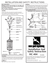
INSTALLATION HC-408
FINAL ASSEMBLY
STEP 1:
S
TEP 4:
STEP 1:
Replace bottom hood (O) and bottom break (P), in that order,
through nipple (R). Secure in place by screwing finial (Q) onto
nipple (R).
CLEANING
ORDERING PARTS
To clean, wipe fixture with a soft cloth. Clean glass with a mild soap.
Do not use abrasive materials such as scouring pads or powders,
steel wool or abrasive paper.
Keep this sheet for future reference, and in case you need to order
replacement parts. All parts for this fixture can be ordered from place
of purchase. Be sure to use exact wording from illustration when
ordering parts.
STEP
2:
STEP 3:
STEP 4:
STEP 2:
STEP 3:
Insert fixture mounting screws (I) in threaded holes of universal
mounting bar (J). Run screws all the way down to the heads.
After wires are connected, tuck them carefully inside the outlet box.
Position backplate (M) over mounting screws (I) and secure in place
with cap nut (N).
Make sure no bare wires can be seen outside wire connectors.
A. Take note of the color of the wire(s) on your fixture. Identify
which group your fixture wire(s) falls into and connect the wires
according to the directions below:
B. Take your fixture wire(s) from group A and place evenly
against the black wire from the outlet box.
Do Not twist wires
together before using wire connectors.
C. Fit a wire connector (not supplied) over the wires and screw
the connector clockwise until you feel a firmness.
D. T
ry gently to pull the connector off the wires. If you can pull
the connector off, carefully re-do steps B and C, as above, and
check again for a firm connection.
E. Connect the fixture wire from group B to the white wire from
the outlet box in the same manner.
Place universal mounting bar (J) against outlet box (not suppplied)
and screw in place using outlet box screws (K) (not supplied). Be
sure the mounting screws are perfectly horizontal so fixture hangs
straight.
IMPORTANT: DO NOT ATTACH FIXTURE DIRECTLY TO OUTLET
BOX.
Install lamps.
Separate bottom hood (O) from cage (F), by unscrewing finial (Q)
and bottom break (P), from nipple (R).
WET LOCA
TION
NOTE: FOR FIXTURES LABELED FOR WET LOCATION AND
USED OUTDOORS.
CAUTION:
To reduce the risk of electrical shock, provide a water-
tight seal between the fixture and the mounting surface by using a
silicone or similar caulking.