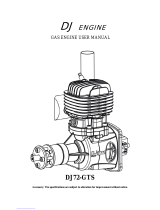
32cc

DLA 32cc, 116cc Twin-Boxer, 116cc-I2 In-line, 128cc QUAD-Boxer, 232cc QUAD Boxer, 58cc, 64-I2 In-Line, 64cc Twin-Boxer Operating Instructions Manual

  • Hello! I am an AI chatbot trained to assist you with the DLA 32cc Operating Instructions Manual. I’ve already reviewed the document and can help you find the information you need or explain it in simple terms. Just ask your questions, and providing more details will help me assist you more effectively!
GS R/C
DLA ENGINE OPERATING-INSTRUCTION
MANUAL
06/29/2016 Copyrighted Material
Owner’s Manual All Rights Reserved 03180-10000
Page - 1 DLA 32, 58, 64, 64-I2, 116, 116-I2 & 128cc, 180c, 232cc Rev. A.05.11
DLA 2-CYCLE GAS ENGINES FOR MODEL AIRCRAFT
This Manual presents the necessary information for the operation of all DLA 2-cycle gasoline,
Model Airplane Engines. DLA 32, 58, 64, 64-I2, 116cc, 116cc-I2 and 128cc QUAD
DLA 32cc DLA 58cc DLA 64cc Twin-Boxer
……………….
DLA 64-I2 In-Line DLA 116cc Twin-Boxer DLA 116cc-I2 In-line
DLA 128cc QUAD-Boxer DLA 18cc Twin Boxer DLA 232cc QUAD Boxer
Manufactured by: FeiaoModel, www.dlaengine.com; USA Distributor: GOLDEN SKIES R/C
Aircraft, Inc. www.goldenskiesrc.com 949-378-5998
GS R/C
DLA ENGINE OPERATING-INSTRUCTION
MANUAL
06/29/2016 Copyrighted Material
Owner’s Manual All Rights Reserved 03180-10000
Page - 2 DLA 32, 58, 64, 64-I2, 116, 116-I2 & 128cc, 180c, 232cc Rev. A.05.11
TABLE OF CONTENTS
Welcome ……………………………….…………………………………….…………….. 3
Legal Disclaimer / Assumption of Liability …………………………………... 4-6
Accessories and Support Items ……………………………………………………. 7-12
About DLA Engines ……………………………………………………………………. 13
Technical Specifications: 32cc, 58cc, 64cc, 116cc, 116-I2, 128cc ………. 13-14
What is in the box ………………………………………………………………………. 14
o Damaged or Missing Parts ………………………….…………………………….. 14-15
Intended Engine Use ………………………………………………………………….. 16
Safety Instructions ……………………………………………………………………… 16-18
Installation in Model Aircraft ………………………………………………………. 18-24
o Mounting Engine to Aircraft Firewall …………………………………………. 18
o Spark Plug ……………………………………………………………………………….. 20
o Muffler ………………………………………………………………………………….…. 20
o Installing Fuel (Gas) Tank, Plumbing …………………………………………. 20
o Ignition Installation and Wiring ………………………………………..….. 20-25
o Engine CDI/Sensor Timing …………………………………………….… 25
o Cowl Ducting and Air Flow ………………………………………………….….. 25
o Temperature Limits …………………………………………………………. 26
Fuel GAS ……………………………………………………………………………….... 26
o Type of Gas and Oils ………………………………………………………………. 26
o Tank Installation ……………………………………………………………………. 26
o Filters ……………………………………………………………………………………. 26
o Fuel Point™ …………………………………………………………………………... 28
116-I2 , 128cc Sensor Connection / Identification ……………………… 24
Propeller Selection ……………………………………………………………………. 24-28
o Drilling the Propeller Bolt Holes ………………………………………... 29
Spinners and Drilling the Back Plate …………………………………………….. 30
Engine Starting .................................................................................... 30
o Break-in …………………………………………………………………………………… 30
o Normal Flight Operation ……………………………………………………………. 31
Engine Maintenance ……………………………………………………………………. 32-36
o Parts Diagram …………………………………………………………………………… 32-37
o Parts List ………………………………………………………………………………….. 33-34
Carburetor Tuning and Care ………………………………………………………… 39-39
Trouble Shooting ………………………………………………………………………… 40-41
Warranty ……………………………………………………………………………………. 43-44
o Warranty Extension …………………………………………………………………… 43
Dimensioned Engine Drawings and Parts Diagram ...……………………….. 32-36
Dimensioned Mounting Guide (Table 1) ………………………..………………. 45
Published Specifications (Table 2) .................…………………………………… 46-50
Torques: Engine Bolts ………………………………………………………………….. 50
Oil:Gas Mixture Table ………………………………………………………………….. 51
GS R/C
DLA ENGINE OPERATING-INSTRUCTION
MANUAL
06/29/2016 Copyrighted Material
Owner’s Manual All Rights Reserved 03180-10000
Page - 3 DLA 32, 58, 64, 64-I2, 116, 116-I2 & 128cc, 180c, 232cc Rev. A.05.11
WELCOME:
Thank you for purchasing the DLA Engine through the GOLDEN SKIES R/C Aircraft, Inc. (GS
R/C) Distributorship and Distribution Channel. Welcome to the world of DLA performance and
GOLDEN SKIES R/C AIRCRAFT, INC. USA service and support. We trust you will find DLA
Engines and GOLDEN SKIES R/C AIRCRAFT, INC. form the perfect combination for excellent
flight performance and service. It is mandatory that you, the consumer read this engine operation
manual entirely and thoroughly, strictly follow all processes and procedures, most specifically the
Safety Instructions and Disclaimer and Legal Liability Sections. If the consumer has any
questions regarding this manual, DLA Engines and the operation thereof, please contact GOLDEN
SKIES R/C AIRCRAFT, INC. at 949-378-5998 for assistance. When the consumer breaks
the seal on the DLA Operations Instructions Manual Envelope, the consumer
acknowledges and agrees with, and to, the Terms and Conditions (T&Cs) listed in
the Safety and Legal Disclaimer Sections of this manual. If the consumer does not
acknowledge and agree to the Terms and Conditions (LEGAL DISCLAIMER / ASSUMPTION
OF LIABILITY: Assumption of Risk Legal agreement only), return the engine to the place
of purchase for a refund. Limitations on the return and refund may apply; see the Warranty
Section of the manual for limitations. Retailer Terms may differ with each individual Retailer.
The consumer must register the DLA Engine warranty within seven (7) days of the original
purchase date, with Golden Skies R/C Aircraft, Inc. for the warranty to apply.
If the envelope seal is already broken, such as might be experienced at a retail store, the original
purchaser must assume the responsibility of acknowledging and agreeing to the Terms and
Conditions of as noted above.
GS R/C
DLA ENGINE OPERATING-INSTRUCTION
MANUAL
06/29/2016 Copyrighted Material
Owner’s Manual All Rights Reserved 03180-10000
Page - 4 DLA 32, 58, 64, 64-I2, 116, 116-I2 & 128cc, 180c, 232cc Rev. A.05.11
LEGAL DISCLAIMER / ASSUMPTION OF LIABILITY:
Assumption of Risk Legal agreement only
Warning
The Radio Controlled (R/C), Aircraft propelled by DLA Engines are NOT Toys and are
potentially dangerous to property and individuals within numerous miles of your flying area. It is
capable of causing substantial property damage, serious bodily harm, and possibly death if it
strikes personal property or an individual.
Consumer’s Responsibility
1) Assembly and Use
IT IS YOUR RESPONSIBILITY AND YOURS ALONE to assemble the Aircraft and DLA Engine
correctly and to properly install all additional components, both included in the DLA Engine kit
and/or acquired by the purchaser of this DLA Engine; to preflight test the model; to follow all
Safety Instructions listed herein, and to fly ONLY in an American Model Aeronautics Association
(AMA) approved flying site with the supervision and/or assistance of a fully qualified flying site
instructor. The pilot of any aircraft must comply with all of the AMA’s Safety Codes. The
employment of common sense for safety of yourself and others is otherwise mandatory. The
aircraft has a radio range of 500 (or less) feet and the pilot is directed not to exceed this distance
when flying the aircraft and DLA Engine. In the event the range is exceeded, the pilot will lose
control of the aircraft which could cause injury and damages to objects which the aircraft may
come into contact with upon an uncontrolled landing. Do not attempt to fly any model aircraft if
you have not been qualified as a solo pilot by the instructor at the AMA approved flying site. It is
recommended that on any first flight of a new R/C aircraft and DLA Engine that you attain the
assistance or instruction of a highly experienced R/C pilot to verify the aircraft and DLA Engine
installation-construction from a safety and flight perspective. If you are just starting to fly R/C
Model Aircraft of any type, consult your local Hobby Shop or write to the Academy of model
Aeronautics to find an experienced instructor in your area.
2) Assumption of the Risk
Participation in the operation of remote controlled aircraft is voluntary. I, the purchaser,
understand that the operation of remote controlled aircraft is a dangerous sport which can result
in bodily injury, death, and/or damage to property for many reasons, including but not limited to
airplane accidents involving third parties known and unknown to the user; equipment failure,
malfunction, or misuse; weather conditions such as storms and lightning; the training, acts,
omissions, recommendations or advice given by your local Hobby Shop or the Academy of model
Aeronautics concerning the operation of remote controlled aircraft and related activities such as
transportation to and from the site; and first-aid, emergency treatment or other services rendered
to me as a user or others. I understand and acknowledge that the above list of reasons is not
complete or exhaustive. I accept and hereby assume all risks of injury, death, illness or disease, or
GS R/C
DLA ENGINE OPERATING-INSTRUCTION
MANUAL
06/29/2016 Copyrighted Material
Owner’s Manual All Rights Reserved 03180-10000
Page - 5 DLA 32, 58, 64, 64-I2, 116, 116-I2 & 128cc, 180c, 232cc Rev. A.05.11
other damage to myself, to others, or to my property which arise from participation in the
referenced activities.
3) Release
I hereby voluntarily release, and forever discharge GOLDEN SKIES R/C AIRCRAFT, INC., a
California Corporation, on its behalf and on the behalf of its successors and assigns, and each of
them (“Golden Skies”) and its subcontractors, and all other persons or entities associated with it,
including other participants, (hereafter collectively the released parties) from all liability, claims,
demands, actions or causes of action for bodily injury, death, illness, disease or damage to myself,
to any participating minor child of mine, or to my property which are related to, arise out of, or
are in any way connected with participation in the above referenced activities, including but not
limited to those arising from any negligent or reckless acts or omissions or breach of contract of
the released parties, or hidden defects in the equipment used. This release is intended to be as
broad and inclusive as is permitted by California law, and shall be construed and interpreted
under California law. If any portion, clause or sub clause is held invalid, I agree that the balance
shall continue in full force and effect.
4) Maintain Proper Insurance Coverage
It is also mandatory that all R/C airplane pilots obtain adequate insurance through their own
homeowner policy or a separate policy to cover liability in the event of property damage or injury
to individuals or personal property. Additionally, all R/C airplane pilots must join the AMA to
become secondarily insured.
Academy of Model Aeronautics http://www.modelaircraft.org ….
Academy of Model Aeronautics
5151 East Memorial Drive
Muncie, Indiana 47302-9252
800-435-9262
5) Indemnification.
The user of DLA Engine products agrees to indemnify FeiaoModel and Golden Skies R/C Aircraft;
and to defend Golden Skies R/C Aircraft, Inc., a California Corporation, as well as all employees,
shareholders, directors, officers and agents thereof (“Golden Skies”) , against any claims, lawsuits
or actions arising as a result of the use of the radio controlled aircraft and DLA Engines, and shall
pay for all legal expenses incurred by Golden Skies in connection with the defense of such matters,
whether or not such claims are resolved without trial or other final decision and whether or not
such expenses are incurred in the defense of litigation or simply incurred prior to litigation in
connection with an informal claim. The obligation of the user to indemnify Golden Skies is express
and unequivocal. The user is expressly obligated to indemnify Golden Skies for Golden Skies’ own
negligence if any, which may give rise to any claim arising in connection with the use or misuse of
the aircraft and DLA Engines or components thereof
6) No reliance
GS R/C
DLA ENGINE OPERATING-INSTRUCTION
MANUAL
06/29/2016 Copyrighted Material
Owner’s Manual All Rights Reserved 03180-10000
Page - 6 DLA 32, 58, 64, 64-I2, 116, 116-I2 & 128cc, 180c, 232cc Rev. A.05.11
I acknowledge that I am not relying on any oral, written, or visual representations or statements
made by the released parties, including those made in released parties catalogs or other
promotional material.
7) Venue
The Venue of any dispute that may arise out of this agreement or otherwise between the parties to
which Golden Skies or its agents is a party shall be Superior Court for the State of California
located in the County of Orange.
Return Policy
If you are not prepared to: 1) obtain adequate insurance to operate the aircraft and DLA
Engine(s); 2) accept all responsibility for personal property damage and /or bodily injury,
including possible death; and 3) to indemnify the engine designer, manufacturer, distributor and
retailer for any liability resulting from your actions, return the complete DLA Engine kit to the
point of purchase for a refund. In order to return the DLA Engine Kit, the following steps must
be undertaken: DLA Engine kit must be presented in its original carton, undamaged and un-
assembled not have been operated. The DLA Engine must be in the original OEM condition and
suitable for resale. Purchaser must show valid purchase receipt. The DLA Engine kit must be
returned to point of purchase with sixty (6) days of original purchase. A restocking fee may be
charged by the retailer. All shipping and handling cost shall be borne by the consumer/purchaser.
Failure to return the DLA engine within the six (6) day period, indicated the
purchaser/user is determined to agree to all the terms and conditions stipulated in
the above LEGAL DISCLAIMER / ASSUMPTION OF LIABILITY section.
Governing Law
Any legal action stemming from the purchase or use of the DLA Engine Products will be governed
by the laws of the State of California and decided by a court of law in the State of California.
GS R/C
DLA ENGINE OPERATING-INSTRUCTION
MANUAL
06/29/2016 Copyrighted Material
Owner’s Manual All Rights Reserved 03180-10000
Page - 7 DLA 32, 58, 64, 64-I2, 116, 116-I2 & 128cc, 180c, 232cc Rev. A.05.11
ACCESSORIES and SUPPORT ITEMS
FUEL POINT:
The proprietary, GOLDEN SKIES R/C AIRCRAFT, INC. Fuel Point™ system pictured below is
the most convenient and popular method of adding gas to your aircraft’s fuel tank. The Fuel
Point™ is installed as shown in the diagram under this manual’s “Tank Installation and
Plumbing Section, or may be downloaded from the www.goldenskiesrc.com . The Fuel Point™
provides fueling through a dedicated fuel line, thus filling the fuel tank directly and without
forcing gas into the carburetor and possibly flooding the engine. It also eliminates extra
plumbing elements such as a “Tee-connector” in the tank-to-carburetor fuel line. This reduces
the possibility of air leaks or perhaps a total disconnection of the main engine fuel supply. The
GS R/C Fuel Pointfunctionality is sometimes referred to as “Fuel Dots.
$19.99, plus S&H from GOLDEN SKIES R/C Aircraft, Inc.
(Prices subject to change without notice in this Operation Manual)
www.goldenskiesrc.com
GS R/C
DLA ENGINE OPERATING-INSTRUCTION
MANUAL
06/29/2016 Copyrighted Material
Owner’s Manual All Rights Reserved 03180-10000
Page - 8 DLA 32, 58, 64, 64-I2, 116, 116-I2 & 128cc, 180c, 232cc Rev. A.05.11
GAS LINE:
The fuel line must be compatible with the Gasoline-Oil mixture used for DLA Engines. GOLDEN
SKIES R/C AIRCRAFT, INC. provides one of the best composite Tygon®-PVC fuel line materials.
The GOLDEN SKIES R/C AIRCRAFT, INC. fuel line tends to remain more flexible over a longer
time period.
Available from Golden Skies R/C Aircraft, Inc.
www.goldenskiesrc.com
OIL:
There are several good manufacturers of 2-cycle oil available. GOLDEN SKIES R/C AIRCRAFT,
INC. does not, at the time of this Manual Revision (A.05) sell or distribute 2-cycle oil.
MOUNTING (Engine) TEMPLATE:
An optional, laser cut, engine mounting template is available from Golden Skies R/C Aircraft, Inc.
The template is universal and applicable for all DLA engines addressed by this current manual
revision. The GS R/C DLA Engine mounting template is the most accurate way to locate the
mounting hole-centers on the aircraft's firewall or engine box.
GS R/C
DLA ENGINE OPERATING-INSTRUCTION
MANUAL
06/29/2016 Copyrighted Material
Owner’s Manual All Rights Reserved 03180-10000
Page - 9 DLA 32, 58, 64, 64-I2, 116, 116-I2 & 128cc, 180c, 232cc Rev. A.05.11
Most aircraft manufactures will provide both Vertical and Horizontal alignment lines (Vc/l and
Hc/l) on the firewall. The template has corresponding Vc/l and Hc/l lines which are aligned to those
scribed on the firewall to accurately locate mounting hole. A paper mounting guide is provided at
the end of this operation manual, but is not as accurate.
Laser Cut Template is available through Golden Skies R/C Aircraft, Inc.
www.goldenskiesrc.com
PN: 03180-50005-A ($9.99)
DRILL BIT GUIDE (for Propeller Bolts)
Specifically engineered Drill Bit Guides (DBG) for each DLA Engine are the preferred and most
accurate method for locating and drilling the holes in the propeller hub for the Propeller Bolts.
GS R/C
DLA ENGINE OPERATING-INSTRUCTION
MANUAL
06/29/2016 Copyrighted Material
Owner’s Manual All Rights Reserved 03180-10000
Page - 10 DLA 32, 58, 64, 64-I2, 116, 116-I2 & 128cc, 180c, 232cc Rev. A.05.11
Shown above is the DBG for the DLA 32cc gas engine. The centering tab on the back of the DBG is
inserted in the prop’s crankshaft hole and the engraved arrows, aligns with the prop’s axis. The
first hole is drilled, using the specified drill bit (see Prop-drill bits below) and then the
alignment/anchoring pin is inserted through the DBG and propeller to secure the DBG while the
remaining holes are drilled.
The GS R/C DLA Drill Bit Guide is available through www.goldenskiesrc.com
Drill Bits:
GOLDEN SKIES R/C AIRCRAFT, INC. stocks metric drill bits in the precise sizes
to match the specific propeller bolts for each of the DLA Engines:
DLA 32cc 4.2 mm GS R/C #: 03180-50001 ($20.99)
DLA 58cc 5.2 mm GS R/C #: 03180-50002 ($20.99)
DLA 64cc 5.2 mm GS R/C #: 03180-50002 ($20.99)
DLA116cc 5.2 mm GS R/C #: 03180-50002 ($20.99)
All DLA Engines have a ten (10) mm crankshaft diameter. The propeller’s
crankshaft hole should be sized to ten (10) mm. The appropriate drill bit is:
10 mm x - 135o GS R/C # 01380-50003
Propeller Bolts:
GOLDEN SKIES R/C AIRCRAFT, INC. stocks the proper Propeller Bolts for each of the DLA
Engines. It is important to use only the specified propeller bolts for proper diameter, thread-
pitch, strength and operation.
The specified prop-Bolts are:
DLA 32cc PN: 01380-00102
DLA 58cc PN: 01380-00202
DLA 64cc PN: 01380-00302
DLA 116 / 116-I2cc PN: 01380-00402
DLA 128cc PN: 01380-00502
PROPELLERS:
The propeller brand selection is somewhat a personal preference and is generally guided by
personal experience and the type of flying desired. Several good propeller manufacturers are
available. Some of the known propeller manufacturers are:
1) Menz 2 ) Mejzlik 3) Beila4) APC 5) Xoar 6) NX
GS R/C
DLA ENGINE OPERATING-INSTRUCTION
MANUAL
06/29/2016 Copyrighted Material
Owner’s Manual All Rights Reserved 03180-10000
Page - 11 DLA 32, 58, 64, 64-I2, 116, 116-I2 & 128cc, 180c, 232cc Rev. A.05.11
SPINNERS:
A sturdy, light weight spinner is best, but they tend to be rather expensive. GOLDEN SKIES R/C
AIRCRAFT, INC. offers lower cost spinners. Please refer to the GOLDEN SKIES R/C AIRCRAFT,
INC. website for spinner selections from two (2) inch to four (4) inch diameter.
www.goldenskiesrc.com/Product_page_Spinners.html
The prop-nut shown on the lower left is not required for DLA Engines; however, you will still
secure the spinner using the “Spinner-bolt” shown on the lower right. The tip of the engine’s
crankshaft is drilled and tapped for a 5.0 mm x 0.8 mm bolt. The length of the spinner-bolt will
depend upon the spinner size.
Spinner Bolts: GS R/C has a stock of spinner-bolts in various lengths. Visit the Golden
Skies R/C Aircraft website to purchase. www.goldenskiesrc.com
GS R/C
DLA ENGINE OPERATING-INSTRUCTION
MANUAL
06/29/2016 Copyrighted Material
Owner’s Manual All Rights Reserved 03180-10000
Page - 12 DLA 32, 58, 64, 64-I2, 116, 116-I2 & 128cc, 180c, 232cc Rev. A.05.11
IGNITION SWITCH:
An Ignition “Kill” Switch (IKS) is required for all DLA Engine / Ignition Installations. Refer to
the installation procedures and diagrams in the “Ignition Installation and Wiring” Section.
GOLDEN SKIES R/C AIRCRAFT, INC. offers the switches that are most commonly used for the
IKS:
IGNITION BATTERY:
All DLA Engine Ignitions operate within a 6.6 V DC to 8.4 V DC range. A 2-Series, LiPo is
commonly used. However, good quality Nickel-Metal-Hydride (NiMH) battery, in a six- (6)
series configuration, is also adequate. An 1100 mAh battery is sufficient. However, a 2100 mAh
battery is recommended for the 64cc and 116cc engines. Check the Golden Skies R/C Aircraft
website for battery selections. The CDI will not operate under 6.0 VDC and damage to the CDI
may occur if the CDI supply voltage is less than 6.0 VDC.
www.goldenskiesrc.com
BOLT SET (Engine):
Complete DLA Engine bolt sets are available for each DLA engine. The Engine bolt set includes
Mounting bolts, prop-bolts, muffler bolts, and appropriate flat-washers and lock-washers.
DLA 32cc PN: 01380-00103
DLA 58cc PN: 01380-00203
DLA 64cc PN: 01380-00303
DLA 116cc PN: 01380-00403
DLA 116 I2cc PN: 03180-01412
DLA 128cc PN: 03180-01624
----------------------------------END OF ACCESSORIES------------------------------------
GS R/C
DLA ENGINE OPERATING-INSTRUCTION
MANUAL
06/29/2016 Copyrighted Material
Owner’s Manual All Rights Reserved 03180-10000
Page - 13 DLA 32, 58, 64, 64-I2, 116, 116-I2 & 128cc, 180c, 232cc Rev. A.05.11
ABOUT DLA ENGINES:
The DLA Engine has been specifically designed, developed and manufactured from proprietary
components for larger (32cc and up) size Model Aircraft. The DLA series of engines are very
powerful, exceptionally light weight for its class, easy to operate and adjust. DLA engines should
provide years of satisfactory performance, if maintained properly. DLA Engines are manufactured
by FeiaoModel in China. See warranty.
Technical Specifications: (See Table 2 for more comprehensive list of Specifications)
DLA - 32cc GAS ENGINE
Displacement: 32cc (1.95 in3)
Horsepower: 3.8 Hp @ 8,200 rpm
Idle: 1,700 rpm
Static Thrust: 19.4 pounds (Pulling Force)*
Props: 18x8, 18x10, 19x8, 20x8
Compression: 7.6 : 1
Spark Plug: CM6-Special, Iridium
Cyl. Dia / Stroke: 37 / 30 mm (1.46” / 1.18”)
Gas:Oil Ratio: 45:1 Typical (Flying)
Weight: 44.6 oz (2.79 lb) (All Components)
DLA - 58cc GAS ENGINE
Displacement: 58cc (3.42 in3)
Horsepower: 6.0 Hp @ 8,500 rpm
Idle: 1,400 rpm
Static Thrust: 33.1 pounds (Pulling Force)*
Props: 22 x 10, 23 x 8/10, 24 x 8
Compression: 7.8 : 1
Spark Plug: CM6-Special, Iridium
Cyl. Dia / Stroke: 46 / 35 mm (1.77” / 1.38”)
Gas:Oil Ratio: 45:1 Typical (Flying_
Weight: 63.1 oz (3.94 lbs) (All Components)
DLA 64cc Gas Engine
Displacement: 64cc (~3.97 in3)
Horsepower: 7.2 @ 8,500 rpm
Idle: 1,400 rpm
Static Thrust: 34.4 pounds -Pulling Force
Props: 22x10, 23x8 /10, 24x8
Compression: 7.8 : 1
Spark Plug: CM6-Special, Iridium
Cyl. Dia / Stroke: 37 / 30 mm (1.46/ 1.18”)
Gas:Oil Ratio: 45:1 Typical (Flying)
GS R/C
DLA ENGINE OPERATING-INSTRUCTION
MANUAL
06/29/2016 Copyrighted Material
Owner’s Manual All Rights Reserved 03180-10000
Page - 14 DLA 32, 58, 64, 64-I2, 116, 116-I2 & 128cc, 180c, 232cc Rev. A.05.11
Weight: 72.4 oz (4.5 lbs) (All Components)
DLA 116cc Twin Boxer
Displacement: 116cc (6.83 in3)
Horsepower: 11.8 @ 7500 rpm
Idle: 1300 rpm
Static Thrust: 59.9 pounds - pulling Force
Props: 26 x 10/12, 27 x 10, 28 x 10
Compression: 7.8 : 1
Spark Plug: CM6-Special, Iridium
Cyl. Dia / Stroke: 46 / 35 mm (1.78”/ 1.38”)
Gas:Oil Ratio: 45:1 Typical (Flying)
Weight: 107.6oz (6.72 lbs) (All Components)
DLA 116cc In-Line Twin
Displacement: 116cc (6.83 in3)
Horsepower: 11.8 @ 7,500 rpm
Idle: 1,300 rpm
Static Thrust: 59.9 pounds (Pulling Force)
Props: 26 x 10/12, 27 x 10, 28 x 10
Compression: 7.8 : 1
Spark Plugs: CM6 Special, Iridium
Cyl. Dia / Stroke: 46 / 35 mm (1.78: / 1.38”)
Gas: Oil Ratio: 45 : 1 Typical (Flying)
Weight: 122.1 oz (7.63 lbs) oz (All Components)
DLA 128cc QUAD BOXER
Displacement: 128cc (7.94 in3)
Horsepower: 13 hp
Idle: 1,250 rpm
Static Thrust: 61 pounds @ 100m (~328 ft)
Props: 27 x 10/12, 28 x 10, 29 x 12
Compression: 7.8 :1
Sparkplugs: CM6 Special, Iridium
Cyl. Dia / Stroke: 37 / 30 mm (1.46”/ 1.18”)
Gas : Oil 45 : 1 Typical (Flying)
Weight: 148.5 oz (9.29 lbs) (All Components)
*Typical Value, User Thrust will vary dependent upon, Propeller, rpm and numerous other factors.
GS R/C
DLA ENGINE OPERATING-INSTRUCTION
MANUAL
06/29/2016 Copyrighted Material
Owner’s Manual All Rights Reserved 03180-10000
Page - 15 DLA 32, 58, 64, 64-I2, 116, 116-I2 & 128cc, 180c, 232cc Rev. A.05.11
ITEMS INCLUDED IN THE RETAIL ENGINE BOX WHEN SHIPPED:
The following items are in the retail box. Any missing or damaged parts must be reported to
GOLDEN SKIES R/C AIRCRAFT, INC. within seven (7) days of the original purchase date to make
a claim for replacement(s):
1. Engine, 1-each
a. Sparkplug, 1-ea DLA 32, 58, and 2-ea DLA 64cc & 116cc, 4-ea 128 QUAD
b. Prop-Washer, 1-each
c. Prop Bolts, 4-each, DLA 32, 58, 64cc and 6-each DLA 116cc, 128 QUAD
d. Ignition Pick-up Sensor and Wire Lead, (2-ea on 64, 116cc, 128QUAD eng.)
e. Carburetor(s)
2. Muffler(s)
a. Gasket, 1-each DLA 32, 58, and 2-each DLA 64cc, 116cc, 4-ea 128cc QUAD
b. Mounting bolts, 2 each DLA 32, 58, and 4 each DLA 64cc, 116cc
3. Ignition, 1-each on 32, 58, 64, 116 Twin, 2-ea on 116-IL & 128 QUAD
a. Silicon Pick-up Wire Wrap Protector and connector Safety Clamps
4. Mounts, Engine (Stand-offs), 4-each
a. Mounting bolts, 8-each for DLA32, 58, 64cc and 4-each for DLA 116, 128cc
5. Operating Manual (visit www.goldenskiesrc.com for the most current Revision)
INTENDED ENGINE USE:
DLA, 2-cycle, Gasoline Engines are designed exclusively for installation in and as the propulsion
system for Radio Controlled Model Aircraft. Any other use is prohibited. Installation is described
in this Operations Manual (PN: 03180-1000, Rev. see footnote). It is the responsibility of the
consumer to install the engine properly using the installation guidelines of this manual as a
minimum standard.
SAFETY INSTRUCTIONS:
DLA Gasoline Engines are not toys and can cause serious injury or death when not
used properly and with extreme caution at all times. Adherence to the Safety
Instructions, here-in, as a minimum requirement, is absolutely mandatory. Read
thoroughly, and become intimately familiar with all safety instructions. Initial each line item
to indicate you have read and understand the instruction. If you do not understand any
or all of the Safety Instruction line items, re-read until you do or consult with the American Model
Aeronautics Association. Further, read the entire DLA Engine Operating Manual and be sure you
are totally familiar and understand each and every item. Learn completely the engines
application, limitations and possible hazards. Review the Safety Instructions
monthly.
GS R/C
DLA ENGINE OPERATING-INSTRUCTION
MANUAL
06/29/2016 Copyrighted Material
Owner’s Manual All Rights Reserved 03180-10000
Page - 16 DLA 32, 58, 64, 64-I2, 116, 116-I2 & 128cc, 180c, 232cc Rev. A.05.11
1. OPERATE IN WELL VENTILATED AREAS: Make sure the area of operation is
well ventilated. Never operate the engine in an enclosed area.
2. INSPECT ALL BOLT FOR SECURITY: Inspect the engine bolts and all engine
components prior to starting and operating the engine:
a. Check the Security of the prop-bolts.
b. Check the Security of the engine mount bolts.
c. Check the Security of all gas line connections.
d. Check to see that the ignition and ignition battery are firmly secured to the
airframe.
e. Confirm the integrity of and proper connection of all ignition wiring.
f. Check to see that the Muffler is securely attached to the engine.
3. USE ENGINE KILL SWITCH: Always install a manual ignition on-off or
engine “kill switch on the outside of the aircraft frame and well back of
the engine propeller.
a. A remotely operated “kill” switch, one that is controlled by the RC Transmitter in
addition to the manual Kill Switch may also be advisable.
4. NEVER OPERATE ENGINE ALONE: Always, have a second person restrain the
aircraft when starting the engine.
5. STAY CLEAR OF ROTATING PROPELLER: Do not lean over, stand in front of
or directly to the side of an operating engine. Do not get within two feet of a rotating
propeller and do not reach toward or point toward the rotating propeller.
6. POINT AIRCRAFT AWAY FROM OTHERS: Be sure the aircraft is pointed away
from all others when starting.
7. KEEP SPECTATORS AWAY: Keep all spectators at least thirty (30) feet away
from the engine and aircraft when preparing to start and operating the engine.
8. WEAR PROPER APPAREL: Do not wear loose clothing, gloves, neckties, jewelry,
neck straps, loose shoe strings or any other item that could become entangled in the
engine’s propeller. The above list may not be all inclusive.
9. DO NOT ADJUST ENGINE WHILE RUNNING: Never try to fix, alter or adjust
anything on the aircraft or engine while the propeller is rotating. Always stop the
engine from running (operating) when making adjustment to the engine.
10. WEAR EYE PROTECTION: Always wear eye protection when operating the
engine. A full face shield is preferred.
11. USE CORRECT PROPELLER SIZE: Always use the correct size propeller (see
Propeller Selection).
a. Be sure the propeller is completely balanced.
b. Check the Prop Bolts for security and always use thread locking material on each
Propeller Bolt.
12. USE FACTORY FURNISHED ENGINE BOLTS: Use the proper length propeller
bolts:
a. DLA 32cc 4.0 mm x 0.7 mm 35 mm Steel Bolts
b. DLA 58cc 5.0 mm x 0.8 mm -- 40 mm Steel Bolts
c. DLA 64cc 5.0 mm x 0.8 mm -- 40 mm Steel Bolts
d. DLA 116cc 5.0 mm x 0.8 mm 50 mm Steel Bolts
13. ENGINE FUEL IS HIGHLY FLAMMABLE AND DANGEROUS: The
Gasoline and Oil, fuel mixture, is highly flammable and dangerous. Keep
the engine fuel container (Gasoline and Oil) in a safe place and at least fifteen (15)
away from the aircraft. Keep the Fuel away from sparks, open flame or anything else
that could accidentally ignite the fuel. Keep fuel away from children. DO NOT
SMOKE within twenty (20) feet of the engine fuel. Have a fire extinguisher on hand.
GS R/C
DLA ENGINE OPERATING-INSTRUCTION
MANUAL
06/29/2016 Copyrighted Material
Owner’s Manual All Rights Reserved 03180-10000
Page - 17 DLA 32, 58, 64, 64-I2, 116, 116-I2 & 128cc, 180c, 232cc Rev. A.05.11
14. OPERATING ENVIRONMENT: Do not operate the engine in the vicinity of loose
materials of any kind, including dirt, sand, gravel, grass (that can reach the propeller),
strings, power cords, and anything else that can be blown by the propellers “prop-
wash” or get caught in, sucked into, or reach the operating propeller. The list above is
not all inclusive.
15. BALANCE SPINNER: Always be sure that the spinner is balanced and installed
according to the spinner manufacturer’s instructions. Do not allow the edges of the
spinner’s propeller cut-outs to touch the propeller.
16. DAMAGED PROPELLER OR SPINNER: Never use a damaged propeller or
spinner: Ex: one that has come into contact with the ground or other objects, or has
been involved in a crash. Do not use a propeller that is split, cracked, pitted or has
any other flaws or damage. Follow all Propeller Manufacturer’s instructions.
17. NEVER THROW ANY ITEM INTO SPINNING PROPELLER: Never attempt
to stop the propeller by injecting or throwing anything into a rotating propeller.
18. USE SPECIFIED ENGINE FUEL LINE: Use only approved fuel line that is
suitable for gasoline and oil.
19. ENGINE GETS HOT: The engine is extremely hot after operation. Do not touch the
engine after running. Allow ample time for the engine to cool off prior to touching it.
20. DO NOT REFUEL WHEN ENGINE IS HOT: Never refuel the aircraft while the
engine is still hot. Allow the engine to cool to a comfortable hand-touchable
temperature before refueling.
21. REMOVE FUEL BEFORE TRANSPORTING: Remove all fuel from the aircraft
fuel tank and engine prior to transporting the aircraft.
22. USE SPECIFIED ENGINE OIL: Use high-quality, 2-cycle oil when mixing with
the gasoline.
23. USE NON-METALLIC THROTTLE PUSH-RODS: The throttle’s push-rod and
clevises should be non-metallic.
24. FILTER FUEL-GAS: Always filter the engine’s fuel when filling the aircraft’s fuel
tank.
25. COMPONENT LOCATIONS: Mount the ignition battery, kill-switch and throttle
servo at least six to twelve (6 - 12) inches to the rear of the aircraft firewall.
26. KILL SWITCH OPERATION: Stay clear of the propeller when switching the Kill-
switch on or off. Accidental ignition may occur and start the engine.
27. COWL AIR FLOW: Provide for proper venting of the cowl to keep the engine cool
while operating.
28. CLEANLINESS: Keep all engine surfaces clean and free from gasoline, oil or other
debris.
29. SPARKPLUG REMOVED: Do not rotate the propeller with the ignition switched
on, while the sparkplug has been removed. Irreversible damage to the ignition system
will occur.
30. LEAN GAS-MIXTURE DAMAGE: Do not run the engine with a “LEAN” gas
mixture. The engine will overheat and permanent damage will occur.
31. FIRE EXTINGUISHER: Always have a portable fire extinguisher on hand and
readily available. Consult with your local fire authority for the best type with respect
to your flying environment.
GS R/C
DLA ENGINE OPERATING-INSTRUCTION
MANUAL
06/29/2016 Copyrighted Material
Owner’s Manual All Rights Reserved 03180-10000
Page - 18 DLA 32, 58, 64, 64-I2, 116, 116-I2 & 128cc, 180c, 232cc Rev. A.05.11
ENGINE INSTALLATION IN MODEL AIRCRAFT
Mount Engine to Model Aircraft Firewall:
Prior to mounting or re-mounting any DLA engine onto the aircraft, review all safety instructions,
check to be sure all engine bolts, plugs, etc. are securely in place. Check the engine thoroughly for
any damage, cracks, or unusual wear.
1. Install the Silicon Wire-wrap Protector over the ignition pick-up wire. Remove any
excess silicon protector.
2. Mount the engine to the aircraft firewall.
a. The firewall must be at least 3/8” (~9.5 mm) thick and perfectly flat.
b. There are three methods for locating the mounting-hole centers on the firewall:
i. PREFERRED: Use the GS R/C DLA Engine Mount Template.
ii. ACCEPTABLE: Use the paper template at the end of this manual
1. Check the dimensions on the paper template by measuring between
the appropriate hole-center locations and confirm they are as
specified either on the paper template or per the dimensions on
Table 1. (Paper can shrink and expand and printing may, and often
does vary dimensionally.)
iii. LEAST PREFERRED: Manually measure the hole locations from the Vc/l
and Hc/l and mark on the firewall as per the engine mount dimensions given
in Table 1.
3. Using the template, align the respective Vc/l and Hc/l on the GS R/C DLA Engine
template or the paper template with the corresponding Vc/l and Hc/l on the aircraft
firewall.
a. NOTE: Follow the alignment procedures described in the model aircraft assembly
manual. The aircrafts manual instructions should allow for any right or down
thrust that may be built into the aircrafts firewall.
b. NOTE: The objective is to have the engines crankshaft be perfectly
aligned with the aircraft thrust-line at the point where the crankshaft
exits the aircraft’s cowl.
4. When the template is aligned properly to the firewall, mark the four (4) mount holes,
center locations with a center punch or an awl. Center punch the awl marks if needed.
5. Drill the engine firewall, mounting holes, using a drill-bit as follows:
a. DLA 32, 58, 64, 116 cc PN: 03180-50000, 5.2 mm OD, 135o
6. Install the DLA stand-offs (included), or use stand-offs of a length to specifically match
the requirements of your model aircraft dimensions. (THE WARRANTY DOES NOT
COVER NON-DLA STAND-OFFS OR DAMAGE CAUSE TO THE DLA ENGINE AS A
RESULT OF USING NON-DLA STAND-OFFS.)
GS R/C
DLA ENGINE OPERATING-INSTRUCTION
MANUAL
06/29/2016 Copyrighted Material
Owner’s Manual All Rights Reserved 03180-10000
Page - 19 DLA 32, 58, 64, 64-I2, 116, 116-I2 & 128cc, 180c, 232cc Rev. A.05.11
a. The cut “squared-off” end of the DLA stand-off attaches to the engine.
b. If additional stand-off length is needed, extra spacers should be placed between the
firewall and the DLA-Stand-off. Extra spacer length such not exceed 10% of the
standoff length. The opposite ends of any spacer must be perfectly parallel, flat and
the diameter should not be less than the DLA Stand-off, flared base.
c. Mount the stand-offs to the firewall and leave the bolts slightly loose for the
moment. Use washers between the bolt-head or nuts and the firewall backside, the
larger in diameter the better…..within reason.
d. Mount the engine to stand-offs using the 4 ea bolts:
i. 5.0 mm x 0.8 mm 2o mm (DLA 32, 58, 64cc)
ii. 5.0 mm x 0.8 mm 50mm (DLA 116, 128cc)
7. Check the alignment of the engine, with the cowl mounted, to determine that the
crankshaft is exiting the cowl properly. (See Model Aircraft Assembly Manual for
Details.)
8. Adjust as necessary and secure all bolts.
a. Use lock washers and thread locking compound on all threads.
9. The supplied stand-offs set the minimum distance between engine’s carburetor and the
firewall. If you use non-DLA Stand-offs, do not decrease this distance. If you cannot
maintain this minimum distance, you may want to consider cutting a hole in the
firewall, directly in line with the carburetor with a diameter approximately equal the
diameter of the carburetor’s intake. DO NOT COMPROMISE THE INTEGRITY OR
STRENGTH OF THE FIREWALL. If you have questions about altering the
firewall, check with the model aircrafts manufacturer or distributor.
10. For the DLA 116cc, where the carburetor generally points downward, there should be
at least 1 to 1-1/2(~38 mm) between the bottom of the carburetor and the cowl.
11. GENERALLY, THE CARBURETOR INTAKE SHOULD BE SITUATED IN “STILL
AIR”. Swirling or turbulent air in or around the carburetor intake can significantly
disrupt the carburetor operation and the cause poor and/or erratic engine
performance. How the air behaves on the ground and in flight is always different and
you may need to control the airflow in and around the carburetor intake.
12. Take note of the carburetor’s High and Low needle valve locations. To avoid having to
remove the cowl for adjustments, you may want to consider making a hole(s) in the
cowl to access these mixture adjustments. With the cowl on or off, engine performance
often differs. Final adjustments with the cowl in place is often more desirable.
13. COWL Vents and Air Flow: Be sure that the cowl openings are sufficient to provide
adequate airflow across the DLA cylinder head fins. Generally, the “rule-of-thumb” is
to have the air exit holes to be three (3) times the size of the air intake. If the air intake
is too big, sufficient air flow may not be directed over the engine’s cooling fins. In such
cases, some air flow directivity may be required, through the use of “air damns” or
vanes.
GS R/C
DLA ENGINE OPERATING-INSTRUCTION
MANUAL
06/29/2016 Copyrighted Material
Owner’s Manual All Rights Reserved 03180-10000
Page - 20 DLA 32, 58, 64, 64-I2, 116, 116-I2 & 128cc, 180c, 232cc Rev. A.05.11
SPARK PLUG:
Install the Special CM6-Special, Iridium Sparkplug supplied in the engine’s cylinder head. Take
care not to cross-thread the plug. The proper torque for the plug is: 7.5 -> 8.0 ft-lbs (~96 in-lbs,
or ~10.2 Nm) for all DLA Engines. The typical spark-plug gap is: 0.018 > 0.02 inches. The gap
is set by the manufacturer, attempting to adjust the gag can damage the hard iridium metal.
MUFFLER INSTALLATION:
Attach the DLA muffler to the engine using the two (2) supplied, 5.0 mm x 0.8 mm 16mm
Socket Head bolts and gasket supplied. No gasket sealant is required. The DLA 64 & 116cc engine
has two (2) mufflers and therefore, four (4) each attachment bolts and two (2) gaskets The 128cc
Quad has eight (8) bolts. Torque each bolt to 60 -> 65 in-lbs (6.7 -> 7.3 N*m). Over torque can
strip the threads. Check bolt tightness after every three or four flights. (see: torques on page 50)
Follow the model aircraft’s assembly manual for providing exit holes for the muffler stacks.
IGNITION INSTALLATION AND WIRING:
All DLA Engine ignition wiring configurations are basically identical. The exception is that the
DLA 64 and 116cc engines have two (2) Ignition or Sparkplug wires running from the Ignition
Module to the two (2) individual Sparkplugs.
Install the ignition in the forward part of the fuselage and isolate it from the airframe with foam
rubber at least 1/2” thick. Secure in place with Velcro® or other like material. Be sure the
location allows all the wiring to reach the intended end points. The ignition wiring diagram is
shown below.
NOTE: When referring to the “SEX” of the connector, it is the connector PINS and Sockets that
determine the sex and not the shape of the connector housing. So, always look at the pins or
sockets. Manual notation is: Male (M) and Female (F). Generally, the sex of the Ignition’s and
the Engine’s connectors are such that they only go together in the correct way.
The step-by-step procedure for the wiring installation is as follows:
1. Step 1: Install the Ignition Kill Switch (IKS) through the side of the fuselage, at a location
easily accessible and safely away from the engine’s propeller.
a. A battery charger connection is built into the ”Super Ignition Switch.
b. Do not charge a LiPo battery while the battery is in the aircraft. Always remove the LiPo
battery and charge in a fire proof, safe location.
2. Step 2: Connect the IKS “Power Switch Wire” to the “Ignition’s Power Wire”. The Ignition Power
Wire is a two (2) wire lead (Red “+ and Black -). An adapter is provided with the engine if
needed. Add a safety clip over the connectors. (Note the optional remote Kill Switch.)
/